EP1653302A2 - Heizfixierrolle mit induktiver Beheizung - Google Patents
Heizfixierrolle mit induktiver Beheizung Download PDFInfo
- Publication number
- EP1653302A2 EP1653302A2 EP05109120A EP05109120A EP1653302A2 EP 1653302 A2 EP1653302 A2 EP 1653302A2 EP 05109120 A EP05109120 A EP 05109120A EP 05109120 A EP05109120 A EP 05109120A EP 1653302 A2 EP1653302 A2 EP 1653302A2
- Authority
- EP
- European Patent Office
- Prior art keywords
- unit
- fusing
- roller
- coil
- heating
- Prior art date
- Legal status (The legal status is an assumption and is not a legal conclusion. Google has not performed a legal analysis and makes no representation as to the accuracy of the status listed.)
- Granted
Links
Images



Classifications
-
- G—PHYSICS
- G03—PHOTOGRAPHY; CINEMATOGRAPHY; ANALOGOUS TECHNIQUES USING WAVES OTHER THAN OPTICAL WAVES; ELECTROGRAPHY; HOLOGRAPHY
- G03G—ELECTROGRAPHY; ELECTROPHOTOGRAPHY; MAGNETOGRAPHY
- G03G15/00—Apparatus for electrographic processes using a charge pattern
- G03G15/20—Apparatus for electrographic processes using a charge pattern for fixing, e.g. by using heat
- G03G15/2003—Apparatus for electrographic processes using a charge pattern for fixing, e.g. by using heat using heat
- G03G15/2014—Apparatus for electrographic processes using a charge pattern for fixing, e.g. by using heat using heat using contact heat
- G03G15/2053—Structural details of heat elements, e.g. structure of roller or belt, eddy current, induction heating
-
- H—ELECTRICITY
- H05—ELECTRIC TECHNIQUES NOT OTHERWISE PROVIDED FOR
- H05B—ELECTRIC HEATING; ELECTRIC LIGHT SOURCES NOT OTHERWISE PROVIDED FOR; CIRCUIT ARRANGEMENTS FOR ELECTRIC LIGHT SOURCES, IN GENERAL
- H05B6/00—Heating by electric, magnetic or electromagnetic fields
- H05B6/02—Induction heating
- H05B6/10—Induction heating apparatus, other than furnaces, for specific applications
- H05B6/14—Tools, e.g. nozzles, rollers, calenders
- H05B6/145—Heated rollers
-
- G—PHYSICS
- G03—PHOTOGRAPHY; CINEMATOGRAPHY; ANALOGOUS TECHNIQUES USING WAVES OTHER THAN OPTICAL WAVES; ELECTROGRAPHY; HOLOGRAPHY
- G03G—ELECTROGRAPHY; ELECTROPHOTOGRAPHY; MAGNETOGRAPHY
- G03G15/00—Apparatus for electrographic processes using a charge pattern
- G03G15/20—Apparatus for electrographic processes using a charge pattern for fixing, e.g. by using heat
- G03G15/2003—Apparatus for electrographic processes using a charge pattern for fixing, e.g. by using heat using heat
- G03G15/2014—Apparatus for electrographic processes using a charge pattern for fixing, e.g. by using heat using heat using contact heat
- G03G15/2017—Structural details of the fixing unit in general, e.g. cooling means, heat shielding means
- G03G15/2025—Structural details of the fixing unit in general, e.g. cooling means, heat shielding means with special means for lubricating and/or cleaning the fixing unit, e.g. applying offset preventing fluid
-
- G—PHYSICS
- G03—PHOTOGRAPHY; CINEMATOGRAPHY; ANALOGOUS TECHNIQUES USING WAVES OTHER THAN OPTICAL WAVES; ELECTROGRAPHY; HOLOGRAPHY
- G03G—ELECTROGRAPHY; ELECTROPHOTOGRAPHY; MAGNETOGRAPHY
- G03G15/00—Apparatus for electrographic processes using a charge pattern
- G03G15/20—Apparatus for electrographic processes using a charge pattern for fixing, e.g. by using heat
- G03G15/2003—Apparatus for electrographic processes using a charge pattern for fixing, e.g. by using heat using heat
- G03G15/2014—Apparatus for electrographic processes using a charge pattern for fixing, e.g. by using heat using heat using contact heat
- G03G15/2017—Structural details of the fixing unit in general, e.g. cooling means, heat shielding means
- G03G15/2028—Structural details of the fixing unit in general, e.g. cooling means, heat shielding means with means for handling the copy material in the fixing nip, e.g. introduction guides, stripping means
-
- G—PHYSICS
- G03—PHOTOGRAPHY; CINEMATOGRAPHY; ANALOGOUS TECHNIQUES USING WAVES OTHER THAN OPTICAL WAVES; ELECTROGRAPHY; HOLOGRAPHY
- G03G—ELECTROGRAPHY; ELECTROPHOTOGRAPHY; MAGNETOGRAPHY
- G03G15/00—Apparatus for electrographic processes using a charge pattern
- G03G15/20—Apparatus for electrographic processes using a charge pattern for fixing, e.g. by using heat
- G03G15/2003—Apparatus for electrographic processes using a charge pattern for fixing, e.g. by using heat using heat
- G03G15/2014—Apparatus for electrographic processes using a charge pattern for fixing, e.g. by using heat using heat using contact heat
- G03G15/2064—Apparatus for electrographic processes using a charge pattern for fixing, e.g. by using heat using heat using contact heat combined with pressure
Definitions
- the present invention relates to a fusing apparatus for use in an image forming apparatus.
- an image forming apparatus using an electrophotographic method such as a laser printer or a digital photocopier, prints a mono-colour image or a full-colour image by scanning light over a photosensitive medium charged to a predetermined electric potential to form an electrostatic latent image.
- the electrostatic latent image is developed using toner of a predetermined colour stored in a developing unit.
- the developed image is transferred and fused onto a sheet of paper.
- Electrophotographic image forming devices are generally classified as wet type or dry type devices.
- Wet type electrophotographic image forming apparatus use a developer that is made by distributing powder toner in a liquid carrier.
- Dry type electrophotographic image forming apparatus uses a binary developer, in which powder carrier and toner are mixed, or a single developer without the carrier.
- a dry type electrophotographic image forming apparatus will be described, and the developer will be referred to as toner.
- FIG. 1 is a transverse cross-sectional view of a fusing apparatus using a halogen lamp as a heat source, according to the conventional art.
- FIG. 2 is a longitudinal cross-sectional view along line I-I' of FIG. 1.
- the fusing apparatus 10 includes two cylindrical fusing rollers 11 and 12 formed of aluminium, which contact each other in a lengthwise direction. Both ends of each of the fusing rollers 11 and 12 are supported by bearings 14. Coating layers 13 are formed on surfaces of the fusing rollers 11 and 12 to hold a piece of paper passing between the rollers 11 and 12 for heating and fusing an image onto the piece of paper.
- a heating unit 15 that uses a halogen lamp as a heat source is connected to an external power source (not shown) to generate heat.
- the heating unit 15 is installed in each fusing roller 11 or 12.
- the heating unit 15 is separated from the fusing roller 11 or 12 by the surrounding air.
- the heating unit 15 When an electric current from the external power source (not shown) is applied to both ends of the heating unit 15, the heating unit 15 generates heat that is transmitted to the inner walls of the fusing rollers 11 and 12 through the air. The heat is then transmitted to an image 21 on a recording medium 20 that passes through the fusing rollers 11 and 12 that contact each other. Therefore, the toner forming the image 21 is melted by the heat energy, and fused onto the recording medium 20.
- the fusing apparatus using the halogen lamp as the heat source has the following problems.
- the halogen lamps and their associated fusing rollers are separated from each other by an air gap, the heat generated by the halogen lamp heats the fusing rollers by radiation, and passes through the fusing rollers by conduction. Therefore, the heat transmission speed is low and heat efficiency is reduced.
- the present invention aims to address the above problems.
- a fusing apparatus for use in an image forming apparatus, the fusing apparatus comprising a fusing roller and means for heating the fusing roller by induction.
- the present invention also provides a fusing roller that has a reduced warm-up time by using induction heating and resistance heating simultaneously and improves heat efficiency by adhering a heating unit to a heated unit using an elastic material, and a fusing apparatus using the fusing roller.
- a fusing roller for fusing an image on a sheet of paper including a coil unit resistance heated by a predetermined alternating current and an alternating magnetic flux generated by the alternating current.
- a heating roller unit is heated by an induced current generated by the alternating magnetic flux.
- An adhering unit is formed of a non-magnetic material and installed to contact the inside of the coil unit to elastically bias the coil unit toward the heating roller unit to adhere the coil unit onto the heating roller unit.
- a fusing apparatus 100 includes a fusing roller 110 that generates heat to fuse a toner image onto paper, and a pressing roller 130 facing the fusing roller 110 and contacting the fusing roller 10 in an axial direction thereof to press the paper passing between the fusing roller 110 and the pressing roller 130 toward the fusing roller 110.
- the pressing roller 130 has a cylindrical body 131 that is rotatably supported by a shaft 133.
- a coating layer 132 is formed on an outer circumferential surface of the body 131 for improving the fusing capability of the fusing apparatus 100. If necessary, a fusing roller may be used instead of using the pressing roller to transmit heat while pressing the paper.
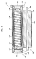
- the fusing roller 110 includes a heating roller unit 112, a coil unit 114, and a biasing or adhering unit 118 for improving contact between the coil unit 114 and the heating roller unit 112.
- the heating roller unit 112 is formed as a hollow cylindrical unit made from, for example, a magnetic substance.
- a coating layer 111 preferably formed of tetrafluoruethylene, is formed on a surface of the heating roller unit 112 for improving the release of the fused toner image from the heating roller unit 112.
- the heating roller unit 112 is preferably made from a material that makes it suitable for induction heating, for example a material that is both conductive and magnetizable by an applied electromagnetic field.
- materials from which the heating roller unit 112 can be formed include ferromagnetic materials such as iron Fe alloys, copper Cu alloys, aluminium Al alloys, nickel Ni alloys and chromium Cr alloys.
- the coil unit 114 comprises a coil that is mounted within the heating roller unit 112, that generates an alternating magnetic field in response to an alternating current input from an external power source (not shown).
- the coil unit 114 is formed using a ribbon coil of copper.
- a first insulating layer 113 is disposed between the coil unit 114 and the heating roller unit 112, and a second insulating layer 115 is disposed between the coil unit 114 and the biasing unit 118.
- the materials used and thicknesses of the first and second insulating layers 113, 115 determine the maximum voltages that can be applied to the coil.
- the first and second insulating layers 113, 115 may, for example, be formed of mica, polyimide, ceramic, silicon, polyurethane, glass, or polytetrafluoruethylene (PTFE).
- the biasing unit 118 for example a coil spring, is mounted in the space 117 in the heating roller unit 112 and biases the coil unit 114 towards the heating roller unit 112. Additionally, since the spring 118 is formed as a spiral within the coil unit 114, the area of the turns of the spring 118 contacting the coil unit 114 is small, and adjacent turns are separated from each other. Thus, the transfer of heat to the spring 118 from the coil unit 114 is substantially prevented.
- the biasing unit 118 is made from a resilient material that is non-magnetic and non-conductive to minimise induction heating effects.
- the biasing unit 118 may take other alternative forms, for instance other structures formed of an elastic or resilient material and arranged to bias the coil unit 114 towards the heating roller unit 112, and to minimise the transfer of heat from the coil unit 114.
- the coil unit 114 can be otherwise mounted or adhered to the inside of the roller 112 without the need for a separate biasing means.
- An end cap 120 and an end cap for transmitting driving power 121 to the roller are installed at respective opposite ends of the heating roller unit 112.
- the power transmission end cap 121 has a similar structure to that of the end cap 120, however, it includes a power transmission unit 124 such as a gear for connecting to a power apparatus (not shown) for rotating the fusing roller 110.
- An air vent 122 is formed on the end cap 120.
- the air vent 122 enables air to flow between the inner space 117 of the heating roller unit 112 and the outside after the end cap 120 is installed on the heating roller unit 112, to prevent the build up of pressure.
- the air vent 122 may be located on the power transmission end cap 121. Alternatively, the air vent 122 may be located on both the end cap 120 and the power transmission end cap 121. However, the air vent 122 is not an essential feature and could, alternatively, be omitted entirely.
- Electrodes 123 are installed on the end cap 120 and the power transmission end cap 121. Each electrode 123 is electrically connected to a respective lead 116 formed at a respective end of the coil unit 114. Electric current is supplied to the coil unit 114 is via the electrodes 123 and the leads 116.
- Fixation units 125 for fixing the biasing unit 118 are installed on the end cap 120 and the power transmission end cap 121. Referring to FIG. 5, the fixation unit 125 has recesses so that both ends 1181 of the biasing unit 118 may be inserted into the recesses.
- the fixation unit 125 is not limited to the shape shown in FIG. 5, however, and may be implemented in any suitable manner so as to connect the biasing unit 118 to the end cap 120 and the power transmission end cap 121.
- the coil unit 114 when an alternating current is supplied to the coil unit 114 by the power supplying unit (not shown), the coil unit 114 generates an alternating magnetic field (A) denoted by a solid line in FIG. 6.
- the alternating magnetic field (A) generated by the coil unit 114 crosses the heating roller unit 112, and generates induced currents B and C, in the heating roller unit 112
- heat G H is generated in both the heating roller unit 112 by induction and by heating of the coil 114 due to current flow within it.
- the heat H from the coil is transmitted to the heating roller unit through the first insulating layer 113 and the heat G, H from the heating roller unit is then transmitted to the toner image through the protective layer 111.
- Induction heating of the roller unit 112 includes both heating due to the induced eddy currents in the conductive material, as well as magnetic hysteresis loss heating that occurs in, for example, ferromagnetic materials.
- the toner image transferred to the recording medium (not shown) is fused onto the medium by the process described above.
- the biasing unit that is formed of a non-magnetic and non-conductive material that resiliently biases the coil unit onto the heating roller unit.
- the coil unit is more effectively adhered to the heating roller unit, while induced current is not generated in the biasing unit. Therefore, the magnetic flux is concentrated in the heating coil unit, and thereby the induced heating efficiency can be improved.
Landscapes
- Physics & Mathematics (AREA)
- General Physics & Mathematics (AREA)
- Electromagnetism (AREA)
- Fixing For Electrophotography (AREA)
- General Induction Heating (AREA)
- Lining Or Joining Of Plastics Or The Like (AREA)
Applications Claiming Priority (1)
| Application Number | Priority Date | Filing Date | Title |
|---|---|---|---|
| KR1020040087060A KR100608010B1 (ko) | 2004-10-29 | 2004-10-29 | 정착롤러 및 이를 적용한 정착장치 |
Publications (3)
| Publication Number | Publication Date |
|---|---|
| EP1653302A2 true EP1653302A2 (de) | 2006-05-03 |
| EP1653302A3 EP1653302A3 (de) | 2006-06-07 |
| EP1653302B1 EP1653302B1 (de) | 2008-08-13 |
Family
ID=35896610
Family Applications (1)
| Application Number | Title | Priority Date | Filing Date |
|---|---|---|---|
| EP05109120A Expired - Lifetime EP1653302B1 (de) | 2004-10-29 | 2005-09-30 | Heizfixierrolle mit induktiver Beheizung |
Country Status (5)
| Country | Link |
|---|---|
| US (1) | US7349661B2 (de) |
| EP (1) | EP1653302B1 (de) |
| KR (1) | KR100608010B1 (de) |
| CN (1) | CN1766757A (de) |
| DE (1) | DE602005008856D1 (de) |
Families Citing this family (4)
| Publication number | Priority date | Publication date | Assignee | Title |
|---|---|---|---|---|
| KR100694063B1 (ko) * | 2004-11-02 | 2007-03-12 | 삼성전자주식회사 | 정착장치 및 이를 적용한 화상형성장치 |
| CN104491814B (zh) * | 2014-12-30 | 2017-12-19 | 兰州古驰生物科技有限公司 | 一种用于调理怕冷畏寒的中药制剂 |
| KR102151872B1 (ko) | 2019-04-16 | 2020-09-03 | 주식회사 에이아이이 | 비접촉식 온도센서모듈을 구비한 유도가열롤러 |
| KR102540506B1 (ko) * | 2020-11-30 | 2023-06-08 | 주식회사 세라젬 | 가압 모듈 및 이를 포함하는 온열 치료기 |
Family Cites Families (25)
| Publication number | Priority date | Publication date | Assignee | Title |
|---|---|---|---|---|
| US4329566A (en) * | 1980-12-12 | 1982-05-11 | Pitney Bowes Inc. | Heated fuser roll |
| JPH07325496A (ja) | 1994-05-31 | 1995-12-12 | Mita Ind Co Ltd | 加熱定着ローラ装置 |
| JP2810355B2 (ja) | 1996-10-15 | 1998-10-15 | ミツマ技研株式会社 | ヒートローラ及びヒートロール定着装置 |
| JP3997025B2 (ja) * | 1998-03-31 | 2007-10-24 | 株式会社リコー | 定着装置 |
| JP3559716B2 (ja) * | 1998-09-25 | 2004-09-02 | 株式会社リコー | 誘導発熱型定着装置とその誘導電流発生部材を製造する方法 |
| JP2000321911A (ja) | 1999-05-16 | 2000-11-24 | Takao Kawamura | 蓄熱型定着用クイックヒートローラー |
| JP2001100575A (ja) * | 1999-07-23 | 2001-04-13 | Canon Inc | 像加熱装置 |
| WO2001048562A1 (fr) * | 1999-12-28 | 2001-07-05 | Toshiba Tec Kabushiki Kaisha | Dispositif de fixage |
| JP3926535B2 (ja) * | 2000-04-04 | 2007-06-06 | 株式会社リコー | 定着装置 |
| JP2002055549A (ja) | 2000-08-10 | 2002-02-20 | Totoku Electric Co Ltd | 加熱ローラ |
| JP2002174973A (ja) * | 2000-10-31 | 2002-06-21 | Toshiba Tec Corp | 定着装置 |
| US6580896B2 (en) * | 2000-12-22 | 2003-06-17 | Samsung Electronics Co., Ltd. | Fusing roller assembly for electrophotographic image forming apparatus |
| KR100400003B1 (ko) * | 2000-12-22 | 2003-09-29 | 삼성전자주식회사 | 전자사진 화상형성 장치의 정착 롤러 장치 |
| JP2002222688A (ja) * | 2001-01-24 | 2002-08-09 | Harison Toshiba Lighting Corp | 誘導加熱ローラ装置、誘導加熱ローラ装置における加熱ローラ、定着装置および画像形成装置 |
| JP2002299032A (ja) | 2001-03-28 | 2002-10-11 | Harison Toshiba Lighting Corp | 誘導加熱装置、誘導加熱ローラ装置、誘導加熱ローラ装置における加熱ローラ、定着装置および画像形成装置 |
| KR100403589B1 (ko) * | 2001-07-09 | 2003-10-30 | 삼성전자주식회사 | 전자사진 화상형성장치의 정착롤러 장치 |
| US6615003B2 (en) * | 2001-09-19 | 2003-09-02 | Kabushiki Kaisha Toshiba | Image forming apparatus |
| WO2003054635A1 (fr) | 2001-12-20 | 2003-07-03 | Canon Finetech Inc. | Rouleau de fixation et son procede de production, dispositif de fixation et dispositif de formation d'images |
| JP2003287968A (ja) | 2002-03-28 | 2003-10-10 | Totoku Electric Co Ltd | 加熱ローラの電磁誘導加熱用励磁コイル部品 |
| JP2003316182A (ja) | 2002-04-24 | 2003-11-06 | Konica Minolta Holdings Inc | 定着装置及び画像形成装置 |
| JP2004144798A (ja) * | 2002-10-22 | 2004-05-20 | Canon Finetech Inc | ローラユニット |
| KR100477678B1 (ko) | 2002-11-11 | 2005-03-21 | 삼성전자주식회사 | 전자사진방식 화상형성장치의 정착장치 |
| KR100476975B1 (ko) * | 2002-12-20 | 2005-03-17 | 삼성전자주식회사 | 화상형성기기의 정착롤러 |
| EP1612620A1 (de) | 2004-06-29 | 2006-01-04 | Samsung Electronics Co., Ltd. | Toneraufschmelzeinheit mit kombinierter Widerstands- und Induktionsheizung |
| EP1612621A1 (de) | 2004-06-29 | 2006-01-04 | Samsung Electronics Co., Ltd. | Schmelzfixiergerät mit einem Transformator gespeisten Widerstand |
-
2004
- 2004-10-29 KR KR1020040087060A patent/KR100608010B1/ko not_active Expired - Fee Related
-
2005
- 2005-08-26 US US11/211,564 patent/US7349661B2/en not_active Expired - Lifetime
- 2005-09-30 CN CN200510108813.3A patent/CN1766757A/zh active Pending
- 2005-09-30 EP EP05109120A patent/EP1653302B1/de not_active Expired - Lifetime
- 2005-09-30 DE DE602005008856T patent/DE602005008856D1/de not_active Expired - Lifetime
Also Published As
| Publication number | Publication date |
|---|---|
| KR100608010B1 (ko) | 2006-08-02 |
| US20060093414A1 (en) | 2006-05-04 |
| EP1653302A3 (de) | 2006-06-07 |
| KR20060037954A (ko) | 2006-05-03 |
| EP1653302B1 (de) | 2008-08-13 |
| CN1766757A (zh) | 2006-05-03 |
| US7349661B2 (en) | 2008-03-25 |
| DE602005008856D1 (de) | 2008-09-25 |
Similar Documents
| Publication | Publication Date | Title |
|---|---|---|
| JP4890991B2 (ja) | 定着装置、これを用いた画像形成装置 | |
| CN100561374C (zh) | 定影装置与图像形成设备 | |
| JP4982000B2 (ja) | 定着装置、画像形成装置 | |
| US6298215B1 (en) | Image heating apparatus | |
| JPH0926717A (ja) | 像加熱装置 | |
| JPH10240050A (ja) | 加熱装置及び画像形成装置 | |
| US7657217B2 (en) | Image heating apparatus and method for manufacturing image heating apparatus | |
| EP1653302B1 (de) | Heizfixierrolle mit induktiver Beheizung | |
| US20120057911A1 (en) | Heating roller comprising induction heating coil made of nickel alloy, fixing unit and image forming apparatus having the same | |
| US7369802B2 (en) | Fusing roller with adjustable heating area and fusing apparatus using the same | |
| US7340207B2 (en) | Fusing roller and fusing apparatus adopting the same | |
| JPH1048976A (ja) | 像加熱用フィルム、像加熱装置及び画像形成装置 | |
| US7158748B2 (en) | Fusing device of an image forming apparatus and method thereof | |
| CN100424596C (zh) | 定影辊与具有该定影辊的定影装置 | |
| KR100547143B1 (ko) | 화상형성장치의 정착장치 | |
| US7565089B2 (en) | Fusing roller and fusing device using the same | |
| JPH10123861A (ja) | 誘導加熱定着装置 | |
| JPH10319751A (ja) | 誘導加熱定着装置 | |
| US7415234B2 (en) | Image fixing device of an image forming apparatus | |
| US20060045586A1 (en) | Fusing roller and fusing apparatus having the same | |
| JPH11190950A (ja) | 像加熱装置及び画像形成装置 | |
| KR20060018157A (ko) | 화상형성기기에서의 정착장치 | |
| JPH10240049A (ja) | 加熱装置及び画像形成装置 | |
| JPH11258932A (ja) | 加熱装置、像加熱装置、及び画像形成装置 | |
| JPH10319750A (ja) | 誘導加熱定着装置 |
Legal Events
| Date | Code | Title | Description |
|---|---|---|---|
| PUAI | Public reference made under article 153(3) epc to a published international application that has entered the european phase |
Free format text: ORIGINAL CODE: 0009012 |
|
| AK | Designated contracting states |
Kind code of ref document: A2 Designated state(s): AT BE BG CH CY CZ DE DK EE ES FI FR GB GR HU IE IS IT LI LT LU LV MC NL PL PT RO SE SI SK TR |
|
| AX | Request for extension of the european patent |
Extension state: AL BA HR MK YU |
|
| PUAL | Search report despatched |
Free format text: ORIGINAL CODE: 0009013 |
|
| AK | Designated contracting states |
Kind code of ref document: A3 Designated state(s): AT BE BG CH CY CZ DE DK EE ES FI FR GB GR HU IE IS IT LI LT LU LV MC NL PL PT RO SE SI SK TR |
|
| AX | Request for extension of the european patent |
Extension state: AL BA HR MK YU |
|
| 17P | Request for examination filed |
Effective date: 20061206 |
|
| 17Q | First examination report despatched |
Effective date: 20070105 |
|
| AKX | Designation fees paid |
Designated state(s): DE FR GB NL |
|
| GRAP | Despatch of communication of intention to grant a patent |
Free format text: ORIGINAL CODE: EPIDOSNIGR1 |
|
| GRAS | Grant fee paid |
Free format text: ORIGINAL CODE: EPIDOSNIGR3 |
|
| GRAA | (expected) grant |
Free format text: ORIGINAL CODE: 0009210 |
|
| AK | Designated contracting states |
Kind code of ref document: B1 Designated state(s): DE FR GB NL |
|
| REG | Reference to a national code |
Ref country code: GB Ref legal event code: FG4D |
|
| REF | Corresponds to: |
Ref document number: 602005008856 Country of ref document: DE Date of ref document: 20080925 Kind code of ref document: P |
|
| PLBE | No opposition filed within time limit |
Free format text: ORIGINAL CODE: 0009261 |
|
| STAA | Information on the status of an ep patent application or granted ep patent |
Free format text: STATUS: NO OPPOSITION FILED WITHIN TIME LIMIT |
|
| 26N | No opposition filed |
Effective date: 20090514 |
|
| PGFP | Annual fee paid to national office [announced via postgrant information from national office to epo] |
Ref country code: DE Payment date: 20130828 Year of fee payment: 9 |
|
| REG | Reference to a national code |
Ref country code: DE Ref legal event code: R119 Ref document number: 602005008856 Country of ref document: DE |
|
| REG | Reference to a national code |
Ref country code: DE Ref legal event code: R119 Ref document number: 602005008856 Country of ref document: DE Effective date: 20150401 |
|
| PG25 | Lapsed in a contracting state [announced via postgrant information from national office to epo] |
Ref country code: DE Free format text: LAPSE BECAUSE OF NON-PAYMENT OF DUE FEES Effective date: 20150401 |
|
| REG | Reference to a national code |
Ref country code: FR Ref legal event code: PLFP Year of fee payment: 12 |
|
| REG | Reference to a national code |
Ref country code: NL Ref legal event code: PD Owner name: S-PRINTING SOLUTION CO., LTD.; KO Free format text: DETAILS ASSIGNMENT: CHANGE OF OWNER(S), ASSIGNMENT; FORMER OWNER NAME: SAMSUNG ELECTRONICS CO., LTD. Effective date: 20170221 |
|
| REG | Reference to a national code |
Ref country code: GB Ref legal event code: 732E Free format text: REGISTERED BETWEEN 20170406 AND 20170412 |
|
| REG | Reference to a national code |
Ref country code: FR Ref legal event code: PLFP Year of fee payment: 13 |
|
| REG | Reference to a national code |
Ref country code: FR Ref legal event code: TP Owner name: S-PRINTING SOLUTION CO., LTD., KR Effective date: 20170912 |
|
| REG | Reference to a national code |
Ref country code: FR Ref legal event code: PLFP Year of fee payment: 14 |
|
| REG | Reference to a national code |
Ref country code: NL Ref legal event code: HC Owner name: HP PRINTING KOREA CO., LTD.; KR Free format text: DETAILS ASSIGNMENT: CHANGE OF OWNER(S), CHANGE OF OWNER(S) NAME; FORMER OWNER NAME: S-PRINTING SOLUTION CO., LTD. Effective date: 20180816 |
|
| REG | Reference to a national code |
Ref country code: NL Ref legal event code: PD Owner name: HEWLETT-PACKARD DEVELOPMENT COMPANY, L.P.; US Free format text: DETAILS ASSIGNMENT: CHANGE OF OWNER(S), CHANGE OF LEGAL ENTITY; FORMER OWNER NAME: SAMSUNG ELECTRONICS CO., LTD. Effective date: 20191030 |
|
| REG | Reference to a national code |
Ref country code: GB Ref legal event code: 732E Free format text: REGISTERED BETWEEN 20191212 AND 20191218 |
|
| PGFP | Annual fee paid to national office [announced via postgrant information from national office to epo] |
Ref country code: NL Payment date: 20210818 Year of fee payment: 17 |
|
| PGFP | Annual fee paid to national office [announced via postgrant information from national office to epo] |
Ref country code: FR Payment date: 20210819 Year of fee payment: 17 |
|
| PGFP | Annual fee paid to national office [announced via postgrant information from national office to epo] |
Ref country code: GB Payment date: 20210820 Year of fee payment: 17 |
|
| REG | Reference to a national code |
Ref country code: NL Ref legal event code: MM Effective date: 20221001 |
|
| GBPC | Gb: european patent ceased through non-payment of renewal fee |
Effective date: 20220930 |
|
| PG25 | Lapsed in a contracting state [announced via postgrant information from national office to epo] |
Ref country code: NL Free format text: LAPSE BECAUSE OF NON-PAYMENT OF DUE FEES Effective date: 20221001 |
|
| PG25 | Lapsed in a contracting state [announced via postgrant information from national office to epo] |
Ref country code: FR Free format text: LAPSE BECAUSE OF NON-PAYMENT OF DUE FEES Effective date: 20220930 |
|
| PG25 | Lapsed in a contracting state [announced via postgrant information from national office to epo] |
Ref country code: GB Free format text: LAPSE BECAUSE OF NON-PAYMENT OF DUE FEES Effective date: 20220930 |