EP1653392A1 - Auswertung von Höchstwerten unter Benutzung eines Federmodells - Google Patents
Auswertung von Höchstwerten unter Benutzung eines Federmodells Download PDFInfo
- Publication number
- EP1653392A1 EP1653392A1 EP04106453A EP04106453A EP1653392A1 EP 1653392 A1 EP1653392 A1 EP 1653392A1 EP 04106453 A EP04106453 A EP 04106453A EP 04106453 A EP04106453 A EP 04106453A EP 1653392 A1 EP1653392 A1 EP 1653392A1
- Authority
- EP
- European Patent Office
- Prior art keywords
- axle
- trailer
- group according
- steering
- peak pattern
- Prior art date
- Legal status (The legal status is an assumption and is not a legal conclusion. Google has not performed a legal analysis and makes no representation as to the accuracy of the status listed.)
- Withdrawn
Links
Images




Classifications
-
- G—PHYSICS
- G06—COMPUTING OR CALCULATING; COUNTING
- G06F—ELECTRIC DIGITAL DATA PROCESSING
- G06F18/00—Pattern recognition
-
- G—PHYSICS
- G06—COMPUTING OR CALCULATING; COUNTING
- G06F—ELECTRIC DIGITAL DATA PROCESSING
- G06F2218/00—Aspects of pattern recognition specially adapted for signal processing
- G06F2218/12—Classification; Matching
Definitions
- the present finding refers, in a totally general way, to trailers or trucks a typical use of which is in the field of agriculture and/or forestry.
- axle group of the modular type that is intended to be associated with the quoted trailers, or trucks.
- a purpose of the finding is that of providing an axle group of the modular type that can be used on trailers or trucks having any number of axles, without the requirement to modify the frame, or flat-bed, of said trailers or trucks in any way.
- a further purpose is that of making a modular axle group the structure of which carries all of the elements making up the group, i.e. constitutes a complete and self-supporting assembly, thus capable of withstanding the twisting stresses that occur, so that the flat-bed of the respective truck or trailer, having to withstand substantially just the flexing stresses due to the generally vertical forces, does not have to be strengthened with transversal braces intended to counteract the quoted twisting stresses as happens according to the prior art.
- Another purpose of the finding consists of making an axle group the wheels, or axle shafts, of which are independent.
- Another purpose is that of making an axle group with independent wheels and with hydraulic control that is suitable for keeping the load constant and equally distributed on each wheel of the trailer irrespective of the position in height of said wheels.
- a further purpose is that of providing an axle group with independent wheels and a hydraulic control, and in general braking, which is structured in such a way as to be able to configure said wheels in steering, self-steering or zero steering mode, according to requirements, at the moment of installation on a trailer.
- Another purpose is that of making an axle group of the modular type and with independent wheels with hydraulic control where the wheels can be adjusted in height according to requirements.
- Yet another purpose is that of achieving the quoted objectives in the context of a simple, strong, rational, reliable, functional and compact constructive solution.
- the axle group of the modular type according to the finding comprises a shaped beam intended to be installed transversally and below the flat-bed of a trailer, and two side-by-side identical underlying small frames that are articulated at one end to the quoted beam according to a common transversal horizontal axis so as to be able to oscillate with respect to the beam, whereas at the other end they are joined to the same beam through a respective member with variable configuration, and they each carry a wheel-carrying hub, or axle shaft.
- said small frames extend beyond said transversal common articulation axis in the opposite direction to the direction of travel of the trailer.
- said member with variable configuration consists of an elastically yielding means, the latter typically in the form of an extensible remote-controlled system that can be adjusted according to requirements (automatically or manually) with the trailer both moving and stationary.
- Said extensible system can advantageously consist of a single or double effect hydraulic jack placed under the control of a hydraulic apparatus comprising at least one pneumatic expansion box, or shock-absorber, suitable for also giving the jack the function, indeed, of a shock-absorber.
- said apparatus is structured so as to also equip said jack for the function of a leveller of the trailer, both when moving and when stationary as stated above, with possible exclusion of the quoted pneumatic expansion box.
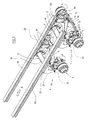
- the aforementioned axle group wholly indicated with reference numeral 1, comprises, in brief, a cross-member 2 that is intended to fix the axle group 1 under the quoted longitudinal members 99, and transversally to them (see FIGS. 3 and 4); two identical underlying small flat frames 3 that are carried by the overlying beam 2; and two complete axle shafts 4 that are set on the outer sides of said small frames 3.
- said cross-member 2 comprises, see in particular FIGS. 1, 5 and 6, a robust horizontal tubular element with polygonal section 20 the opposite ends of which are fixed to two vertical box-shaped brackets 21.
- the two brackets 21 are shaped forming a right angle, and their dihedral faces downwards and towards the rear zone of the trailer. It should be specified that there is nothing to prevent the brackets 21 from being orientated in the opposite direction, i.e. with the dihedral facing downwards and forwards.
- each bracket 21 carries a platband 22 that is intended to be advantageously fixed under a respective longitudinal member 99, for example with bolts (FIG. 5) or through welding (FIG. 1).
- FIGS. 1-4 A complete description of the example embodiment according to FIGS. 1-4 is shown hereafter.
- the quoted holes define a transversal horizontal axis, indicated with 33 in the figures, which constitutes the common front hinging axis of the small frames 3 to the overlying cross-member 2. This takes place through four suitable pins, the two central ones being indicated with 30, and the outer ones being indicated with 31.
- Each individual small frame 3 consists of a flat box-shaped structure 130 lying practically horizontally, which in plan has a form generally shaped like a fork with concavity facing in the direction of travel A.
- the inner arm of said fork-shape is articulated to the respective central pin 30; the outer arm of the same fork-shape is hinged to the respective outer pin 31; and the cross-member of the same fork-shape has, substantially at the centre, a vertical through opening 34 that in plan has the shape of a slot with longitudinal extension perpendicular to the axis 33.
- a fork 35 is fixed that faces the lower mouth of said opening 34, and the arms of which are perforated (see FIG. 2), to provide the seat for a transversal horizontal pin 36 (FIGS. 1 to 4).
- the quoted pin 36 has the lower end of a member with variable configuration 37 articulated to it, in the present case consisting of an elastically yielding means 37 that crosses the opening 34 with clearance, beyond which with the opposite upper end it is articulated at 38 (FIG. 1) below the horizontal arm of the respective bracket 21.
- said elastically yielding means consists of a single or double effect hydraulic jack the operative chambers of which are connected to a suitable command and control hydraulic apparatus arranged on board the tractor.
- This apparatus which amongst other things comprises at least one expansion box or pneumatic shock-absorber, shall be better defined hereafter.
- each small frame 3 has a complete axle shaft 4, i.e. equipped with a respective steering group and with a respective braking group, associated with it.
- axle shafts 4 are generally of the known type, and each of them comprises the following members.
- a bracket generally shaped to form a right-angle 40 that is coplanar with the small frame 3, and the dihedral of which faces forwards and towards the centre of the axle group 1.
- the steering arm 42 is articulated to the pin 44.
- the quoted arm 42 carries, see in particular FIG. 2, on the upper-front side, a support 45 for holding a service pneumatic expansion box 145 for braking; on the outer side the hub-carrying disc 43 with relative winding drum 143 for the attachment of a wheel (rim + tire), not shown for the sake of simplicity and clarity; and at the rear end an eyelet 46.
- Said expansion box 145 per sé normal, is intended, upon the command of the driver of the car that pulls the trailer, to actuate an equally normal lever system 47 with which to activate the braking device (not visible in the figures) arranged between disc 43 and drum 143.
- the eyelets 46 of the steering arms of two aligned axle shafts 4 are joined together by a transversal shaft 5 that is in turn connected, through a central block indicated with 6, to a rod 7 that connects two elastically yielding head devices 77 to the central block 6.
- said rod 7 consists of two identical shock absorbers that are set on either side of the quoted block 6.
- said devices 77 are set behind the small frames 3, and connect them to the inner sides of the steering arms 42 (see Fig. 1 on the right).
- axle group 1 is structured, positioned and sized in such a way as to be able to readily configure the axle group 1 according to the three operating modes indicated hereafter.
- the first mode which we shall call fixed or with zero steering, is the one the foresees installing the axle group 1 on a trailer without the quoted assembly of elements 5, 7 and 77, the disassembly of which comes down to very little given the simple attachment system clearly illustrated in FIG. 1, and simultaneously disabling the specific function of the pins 44, thanks to a suitable blocking system (not visible in the figures), for example consisting of a simple transversal bolt accessible from the outside.
- Examples of said first mode are given by the front axle group 1 according to FIG. 3 and by the central axle group 1 according to FIG. 4.
- the second mode which we shall call self-steering, is the one that foresees installing the entire axle group 1 as shown in FIG. 1; enabling the pins 44; and providing the elastically yielding devices 77 in the form of double effect hydraulic jacks.
- the operative chambers of the quoted jacks are connected to the hydraulic apparatus (hydraulic distributor) generally arranged on the tractor, and the shock-absorbing effect is given to the component elements of the rod 7, which also operate as anti-wobbling means.
- the quoted devices 77 are slaved to the hydroguide of the steer of the car pulling the trailer, typically through its own command and control hydraulic apparatus, so as to control the steering of the wheels of the axle group 1, limiting it.
- command and control hydraulic apparatus which as stated has at least one expansion box or pneumatic shock-absorber, performs at least the following functions.
- Said levelling action can obviously be enabled both with the trailer moving and stationary, and can advantageously be exploited in various situations.
- it can be used to ease loading and unloading operations of the trailer when stationary, for example by inclining the flat-bed either longitudinally forwards or backwards, or transversally towards one side or the other.
- the quoted apparatus is equipped with means thanks to which the length of the hydraulic cylinders or jacks 37 can be modified as desired at the same time or not as the action of the expansion box or pneumatic shock-absorber.
- FIGS. 5 and 6 operates substantially with the same modes explained with reference to the example according to FIGS. 1-4, and can be associated with a truck or trailer for example as indicated in FIGS. 3 and 4.
- FIGS. 1-4 The main differences between the first embodiment fully described above (FIGS. 1-4) and the variant according to FIGS. 5 and 6 are substantially the following.
- each individual small frame 3 consists of a flat box-shaped structure 230 lying practically horizontally, which in plan has a form generally shaped to form a right-angle, or elbow.
- the two wings of said right-angle shape are respectively arranged parallel and perpendicular to the direction of travel A, and its dihedral faces towards the outside and in the direction of travel A.
- the first of said wings is articulated under the beam 2 through a respective single pin 133, and the second carries the respective complete axle shaft 4, with the elastically yielding device 77 behind.
- Said dihedral receives the jack 37, which at the top is articulated to the respective bracket 21 through the transversal horizontal pin 38, whereas at the bottom it is articulated to the transversal horizontal pin 36 that is carried by two descending ears 330 (see FIG. 6) deriving from the transversal wing of the small frame 3.
- the rod 7 forming part of the steering linkage of the axle shafts 4 is split into two distinct shock-absorbers each of which has the outer end directly hinged to the respective steering arm 42, and the inner arm directly hinged under the respective small frame 3.
Landscapes
- Engineering & Computer Science (AREA)
- Theoretical Computer Science (AREA)
- Bioinformatics & Computational Biology (AREA)
- Physics & Mathematics (AREA)
- Life Sciences & Earth Sciences (AREA)
- Computer Vision & Pattern Recognition (AREA)
- Data Mining & Analysis (AREA)
- Evolutionary Biology (AREA)
- Evolutionary Computation (AREA)
- Bioinformatics & Cheminformatics (AREA)
- General Engineering & Computer Science (AREA)
- General Physics & Mathematics (AREA)
- Artificial Intelligence (AREA)
- Investigating Strength Of Materials By Application Of Mechanical Stress (AREA)
- Vehicle Body Suspensions (AREA)
- Investigating Or Analysing Biological Materials (AREA)
Priority Applications (2)
| Application Number | Priority Date | Filing Date | Title |
|---|---|---|---|
| EP04106453A EP1653392A1 (de) | 2004-12-10 | 2004-12-10 | Auswertung von Höchstwerten unter Benutzung eines Federmodells |
| US11/299,160 US7574328B2 (en) | 2004-12-10 | 2005-12-09 | Peak pattern evaluation using spring model |
Applications Claiming Priority (1)
| Application Number | Priority Date | Filing Date | Title |
|---|---|---|---|
| EP04106453A EP1653392A1 (de) | 2004-12-10 | 2004-12-10 | Auswertung von Höchstwerten unter Benutzung eines Federmodells |
Publications (2)
| Publication Number | Publication Date |
|---|---|
| EP1653392A1 true EP1653392A1 (de) | 2006-05-03 |
| EP1653392A9 EP1653392A9 (de) | 2007-02-21 |
Family
ID=34930030
Family Applications (1)
| Application Number | Title | Priority Date | Filing Date |
|---|---|---|---|
| EP04106453A Withdrawn EP1653392A1 (de) | 2004-12-10 | 2004-12-10 | Auswertung von Höchstwerten unter Benutzung eines Federmodells |
Country Status (2)
| Country | Link |
|---|---|
| US (1) | US7574328B2 (de) |
| EP (1) | EP1653392A1 (de) |
Families Citing this family (1)
| Publication number | Priority date | Publication date | Assignee | Title |
|---|---|---|---|---|
| US7831414B2 (en) * | 2006-10-06 | 2010-11-09 | Qualcomm Incorporated | Method and apparatus for detecting a presence of a signal in a communication channel |
Citations (2)
| Publication number | Priority date | Publication date | Assignee | Title |
|---|---|---|---|---|
| US5119315A (en) * | 1989-04-28 | 1992-06-02 | Amoco Corporation | Method of correlating a record of sample data with a record of reference data |
| US20030026465A1 (en) * | 1997-06-24 | 2003-02-06 | Anderson N. Leigh | Method for computer-assisted isolation and characterization of proteins |
Family Cites Families (6)
| Publication number | Priority date | Publication date | Assignee | Title |
|---|---|---|---|---|
| US4008388A (en) * | 1974-05-16 | 1977-02-15 | Universal Monitor Corporation | Mass spectrometric system for rapid, automatic and specific identification and quantitation of compounds |
| US6161080A (en) * | 1997-11-17 | 2000-12-12 | The Trustees Of Columbia University In The City Of New York | Three dimensional multibody modeling of anatomical joints |
| US6210465B1 (en) * | 1999-03-17 | 2001-04-03 | Agilent Technologies, Inc. | Method for identification of components within a known sample |
| US7085688B1 (en) * | 1999-10-22 | 2006-08-01 | Shizuo Sumida | Non-linear characteristic reproducing apparatus and non-linear characteristic reproducing program storage medium |
| JPWO2005024728A1 (ja) * | 2003-09-03 | 2007-11-08 | 日本電気株式会社 | 形態変形装置、物体動作符号化装置および物体動作復号化装置 |
| CA2457376C (en) * | 2003-10-14 | 2015-09-15 | The University Of British Columbia | Method for imaging the mechanical properties of tissue |
-
2004
- 2004-12-10 EP EP04106453A patent/EP1653392A1/de not_active Withdrawn
-
2005
- 2005-12-09 US US11/299,160 patent/US7574328B2/en active Active
Patent Citations (2)
| Publication number | Priority date | Publication date | Assignee | Title |
|---|---|---|---|---|
| US5119315A (en) * | 1989-04-28 | 1992-06-02 | Amoco Corporation | Method of correlating a record of sample data with a record of reference data |
| US20030026465A1 (en) * | 1997-06-24 | 2003-02-06 | Anderson N. Leigh | Method for computer-assisted isolation and characterization of proteins |
Non-Patent Citations (11)
| Title |
|---|
| ADDARIO-BERRY: "2D Gel Electrophoresis - An Overview", COURSE AT MCGILL UNIVERSITY, MONTREAL, CANADA ALGORITHMS FOR GENE EXPRESSION AND PROTEOMICS, 9 May 2002 (2002-05-09), pages 1 - 9, XP002327941, Retrieved from the Internet <URL:http://www.mcb.mcgill.ca/~hallett/GEP/PLecture3/PLecture3.pdf> [retrieved on 20050512] * |
| HONGTAO DU ET AL: "Modeling mobile-agent-based collaborative processing in sensor networks using generalized stochastic petri nets", 2003 IEEE INTERNATIONAL CONFERENCE ON SYSTEMS, MAN AND CYBERNETICS. SMC'03. CONFERENCE PROCEEDINGS. WASHINGTON, DC, OCT. 5 - 8, 2003, IEEE INTERNATIONAL CONFERENCE ON SYSTEMS, MAN, AND CYBERNETICS, NEW YORK, NY : IEEE, US, vol. VOL. 5 OF 5, 5 October 2003 (2003-10-05), pages 563 - 568, XP010666803, ISBN: 0-7803-7952-7 * |
| LEMKIN P F ET AL: "GELLAB: A COMPUTER SYSTEM FOR 2D GEL ELECTROPHORESIS ANALYSIS. II. PAIRING SPOTS", COMPUTERS AND BIOMEDICAL RESEARCH, ACADEMIC PRESS, LONDON, GB, vol. 14, no. 4, August 1981 (1981-08-01), pages 355 - 380, XP001051303, ISSN: 0010-4809 * |
| LI BAIHUA; MENG QINGGANG; HOLSTEIN HORST: "Point pattern matching and applications-a review", PROCEEDINGS OF THE 2003 IEEE INTERNATIONAL CONFERENCE ON SYSTEMS, MAN AND CYBERNETICS, vol. 1, 2003, PISCATAWAY, NJ, USA, pages 729 - 736, ISBN: 0-7803-7952-7 * |
| MINGTIAN NI; QINGPING TAO; REICHENBACH S.E.: "MCMC-based peak template matching for GCXGC", PROCEEDINGS OF THE 2003 IEEE WORKSHOP ON STATISTICAL SIGNAL PROCESSING, 28 September 2003 (2003-09-28), PISCATAWAY, NJ, USA, pages 514 - 517, XP010699919, ISBN: 0-7803-7997-7, Retrieved from the Internet <URL:http://cse.unl.edu/~reich/publications/wssp2003-tp5-5.pdf> [retrieved on 20051111] * |
| NI M; REICHENBACH S.E.: "Using edge pattern matching for automatic chemical identification in GCXGC", PROCEEDINGS OF THE SPIE: AUTOMATIC TARGET RECOGNITION XIV, vol. 5426, no. 1, September 2004 (2004-09-01), SPIE-INT. SOC. OPT. ENG., USA, pages 155 - 163, XP008055652, ISSN: 0277-786X, Retrieved from the Internet <URL:http://cse.unl.edu/~mni/publications/epm.pdf> [retrieved on 20051111] * |
| PANEK, JOSEF; VOHRADSKY, JIRI: "Point pattern matching in the analysis of two-dimensional gel electropherograms", ELECTROPHORESIS, vol. 20, 1999, WEINHEIM, GERMANY, pages 3483 - 3491, XP002327932, Retrieved from the Internet <URL:http://sun2.biomed.cas.cz/mbu/proteom/download/panek_electrophoresis_1999.pdf> [retrieved on 20050512] * |
| SHINKI UMEYAMA: "A POINT PATTERN MATCHING ALGORITHM", SYSTEMS & COMPUTERS IN JAPAN, SCRIPTA TECHNICA JOURNALS. NEW YORK, US, vol. 20, no. 10, 1 October 1989 (1989-10-01), pages 95 - 106, XP000128838, ISSN: 0882-1666 * |
| VAN WAMELEN P B ET AL: "A fast expected time algorithm for the 2-D point pattern matching problem", PATTERN RECOGNITION, ELSEVIER, KIDLINGTON, GB, vol. 37, no. 8, August 2004 (2004-08-01), pages 1699 - 1711, XP004512288, ISSN: 0031-3203 * |
| WANG YAO; LEE OUSEB: "Active Mesh - A feature Seeking and Tracking Image Sequence Representation Scheme", IEEE TRANSACTIONS ON IMAGE PROCESSING, vol. 3, no. 5, September 1994 (1994-09-01), USA, pages 610 - 624, XP000476835, ISSN: 1057-7149 * |
| ZHANG J ET AL: "FACE RECOGNITION: EIGENFACE, ELASTIC MATCHING, AND NEURAL NETS", PROCEEDINGS OF THE IEEE, IEEE. NEW YORK, US, vol. 85, no. 9, 1 September 1997 (1997-09-01), pages 1423 - 1435, XP000738565, ISSN: 0018-9219 * |
Also Published As
| Publication number | Publication date |
|---|---|
| EP1653392A9 (de) | 2007-02-21 |
| US20060126065A1 (en) | 2006-06-15 |
| US7574328B2 (en) | 2009-08-11 |
Similar Documents
| Publication | Publication Date | Title |
|---|---|---|
| CN101164802B (zh) | 悬架的分组装件 | |
| US2742301A (en) | Deformable cushion suspension for vehicles | |
| US6808035B1 (en) | Tandem rear axle suspensions for trucks and truck-tractors | |
| US9517674B2 (en) | Pneumatic control system for a heavy-duty vehicle | |
| CA2174618C (en) | Transport vehicle for taking up and taking down containers and the like onto or from a loading platform thereof | |
| CN101484329A (zh) | 车辆悬架高低控制 | |
| US20190061847A1 (en) | Tandem lift auxiliary axle assembly | |
| US6193266B1 (en) | Vocational air ride tandem axle suspensions | |
| CA2034973A1 (en) | High lift tag axle for trucks | |
| US4279430A (en) | Fifth-wheel suspension system | |
| AU2012255618B2 (en) | Improvements to haul bodies and related apparatus | |
| US6435526B1 (en) | Axle lifting device for a vehicle | |
| EP1574367A9 (de) | Achs-Baugruppe für die Verwendung in Anhängern | |
| NL2019948B1 (en) | Axle lift | |
| GB2191741A (en) | Adjustable trailer wheel suspensions | |
| US9340078B2 (en) | Hydraulic equalizing spreader bar with dual spread links | |
| US3827518A (en) | Suspension system for hitch assembly | |
| US7207587B1 (en) | Remote controlled hydraulic gooseneck for tractor trailers | |
| EP0166882B1 (de) | Höhenverstellbare Luftfederung | |
| WO1998030404A1 (en) | Tandem rear axle suspensions for trucks and truck-tractors | |
| AU2023336527A1 (en) | Axle structure for a commercial vehicle chassis having an axle bridge | |
| EP0968906B1 (de) | Traktor mit einer Zusatzachse für Traktoranhänger- Kombination | |
| NZ331383A (en) | Improvements in air vehicle suspension units comprising control means to vary the air pressure | |
| AU2013201290B2 (en) | Improvements to haul bodies | |
| GB1562894A (en) | Road vehicle suspension |
Legal Events
| Date | Code | Title | Description |
|---|---|---|---|
| PUAI | Public reference made under article 153(3) epc to a published international application that has entered the european phase |
Free format text: ORIGINAL CODE: 0009012 |
|
| 17P | Request for examination filed |
Effective date: 20050716 |
|
| AK | Designated contracting states |
Kind code of ref document: A1 Designated state(s): AT BE BG CH CY CZ DE DK EE ES FI FR GB GR HU IE IS IT LI LT LU MC NL PL PT RO SE SI SK TR |
|
| AX | Request for extension of the european patent |
Extension state: AL BA HR LV MK YU |
|
| GRAP | Despatch of communication of intention to grant a patent |
Free format text: ORIGINAL CODE: EPIDOSNIGR1 |
|
| RIC1 | Information provided on ipc code assigned before grant |
Ipc: G06K 9/00 20060101AFI20060725BHEP |
|
| GRAJ | Information related to disapproval of communication of intention to grant by the applicant or resumption of examination proceedings by the epo deleted |
Free format text: ORIGINAL CODE: EPIDOSDIGR1 |
|
| AKX | Designation fees paid |
Designated state(s): CH DE FR GB LI |
|
| RAP1 | Party data changed (applicant data changed or rights of an application transferred) |
Owner name: AGILENT TECHNOLOGIES, INC. |
|
| APBN | Date of receipt of notice of appeal recorded |
Free format text: ORIGINAL CODE: EPIDOSNNOA2E |
|
| APBR | Date of receipt of statement of grounds of appeal recorded |
Free format text: ORIGINAL CODE: EPIDOSNNOA3E |
|
| APAF | Appeal reference modified |
Free format text: ORIGINAL CODE: EPIDOSCREFNE |
|
| APBT | Appeal procedure closed |
Free format text: ORIGINAL CODE: EPIDOSNNOA9E |
|
| STAA | Information on the status of an ep patent application or granted ep patent |
Free format text: STATUS: THE APPLICATION IS DEEMED TO BE WITHDRAWN |
|
| 18D | Application deemed to be withdrawn |
Effective date: 20100701 |