EP1653543A2 - Conception de champ d'écoulement pour pile à combustible à utilisation élevée de combustible - Google Patents
Conception de champ d'écoulement pour pile à combustible à utilisation élevée de combustible Download PDFInfo
- Publication number
- EP1653543A2 EP1653543A2 EP05254893A EP05254893A EP1653543A2 EP 1653543 A2 EP1653543 A2 EP 1653543A2 EP 05254893 A EP05254893 A EP 05254893A EP 05254893 A EP05254893 A EP 05254893A EP 1653543 A2 EP1653543 A2 EP 1653543A2
- Authority
- EP
- European Patent Office
- Prior art keywords
- flow
- channel
- flow field
- barriers
- field
- Prior art date
- Legal status (The legal status is an assumption and is not a legal conclusion. Google has not performed a legal analysis and makes no representation as to the accuracy of the status listed.)
- Granted
Links
- 239000000446 fuel Substances 0.000 title claims abstract description 55
- 230000004888 barrier function Effects 0.000 claims abstract description 41
- 239000000758 substrate Substances 0.000 claims abstract description 14
- 239000007787 solid Substances 0.000 claims abstract description 12
- 230000007423 decrease Effects 0.000 abstract description 8
- 239000003792 electrolyte Substances 0.000 description 13
- 238000010586 diagram Methods 0.000 description 12
- 239000000376 reactant Substances 0.000 description 6
- 239000007800 oxidant agent Substances 0.000 description 4
- 238000006243 chemical reaction Methods 0.000 description 3
- UFHFLCQGNIYNRP-UHFFFAOYSA-N Hydrogen Chemical compound [H][H] UFHFLCQGNIYNRP-UHFFFAOYSA-N 0.000 description 2
- QVGXLLKOCUKJST-UHFFFAOYSA-N atomic oxygen Chemical compound [O] QVGXLLKOCUKJST-UHFFFAOYSA-N 0.000 description 2
- 230000003247 decreasing effect Effects 0.000 description 2
- 238000009792 diffusion process Methods 0.000 description 2
- 239000001257 hydrogen Substances 0.000 description 2
- 229910052739 hydrogen Inorganic materials 0.000 description 2
- 230000001590 oxidative effect Effects 0.000 description 2
- 239000001301 oxygen Substances 0.000 description 2
- 229910052760 oxygen Inorganic materials 0.000 description 2
- 229910001233 yttria-stabilized zirconia Inorganic materials 0.000 description 2
- 241000270295 Serpentes Species 0.000 description 1
- CETPSERCERDGAM-UHFFFAOYSA-N ceric oxide Chemical compound O=[Ce]=O CETPSERCERDGAM-UHFFFAOYSA-N 0.000 description 1
- 229910000422 cerium(IV) oxide Inorganic materials 0.000 description 1
- 239000007795 chemical reaction product Substances 0.000 description 1
- 239000004020 conductor Substances 0.000 description 1
- LNTHITQWFMADLM-UHFFFAOYSA-N gallic acid Chemical compound OC(=O)C1=CC(O)=C(O)C(O)=C1 LNTHITQWFMADLM-UHFFFAOYSA-N 0.000 description 1
- 239000010416 ion conductor Substances 0.000 description 1
- 229910052746 lanthanum Inorganic materials 0.000 description 1
- FZLIPJUXYLNCLC-UHFFFAOYSA-N lanthanum atom Chemical compound [La] FZLIPJUXYLNCLC-UHFFFAOYSA-N 0.000 description 1
- 230000001737 promoting effect Effects 0.000 description 1
- 241000894007 species Species 0.000 description 1
- 229910002076 stabilized zirconia Inorganic materials 0.000 description 1
Images






Classifications
-
- H—ELECTRICITY
- H01—ELECTRIC ELEMENTS
- H01M—PROCESSES OR MEANS, e.g. BATTERIES, FOR THE DIRECT CONVERSION OF CHEMICAL ENERGY INTO ELECTRICAL ENERGY
- H01M8/00—Fuel cells; Manufacture thereof
- H01M8/02—Details
- H01M8/0202—Collectors; Separators, e.g. bipolar separators; Interconnectors
- H01M8/0258—Collectors; Separators, e.g. bipolar separators; Interconnectors characterised by the configuration of channels, e.g. by the flow field of the reactant or coolant
- H01M8/0265—Collectors; Separators, e.g. bipolar separators; Interconnectors characterised by the configuration of channels, e.g. by the flow field of the reactant or coolant the reactant or coolant channels having varying cross sections
-
- H—ELECTRICITY
- H01—ELECTRIC ELEMENTS
- H01M—PROCESSES OR MEANS, e.g. BATTERIES, FOR THE DIRECT CONVERSION OF CHEMICAL ENERGY INTO ELECTRICAL ENERGY
- H01M8/00—Fuel cells; Manufacture thereof
- H01M8/02—Details
-
- H—ELECTRICITY
- H01—ELECTRIC ELEMENTS
- H01M—PROCESSES OR MEANS, e.g. BATTERIES, FOR THE DIRECT CONVERSION OF CHEMICAL ENERGY INTO ELECTRICAL ENERGY
- H01M8/00—Fuel cells; Manufacture thereof
- H01M8/02—Details
- H01M8/0202—Collectors; Separators, e.g. bipolar separators; Interconnectors
- H01M8/0258—Collectors; Separators, e.g. bipolar separators; Interconnectors characterised by the configuration of channels, e.g. by the flow field of the reactant or coolant
-
- H—ELECTRICITY
- H01—ELECTRIC ELEMENTS
- H01M—PROCESSES OR MEANS, e.g. BATTERIES, FOR THE DIRECT CONVERSION OF CHEMICAL ENERGY INTO ELECTRICAL ENERGY
- H01M8/00—Fuel cells; Manufacture thereof
- H01M8/02—Details
- H01M8/0202—Collectors; Separators, e.g. bipolar separators; Interconnectors
- H01M8/0258—Collectors; Separators, e.g. bipolar separators; Interconnectors characterised by the configuration of channels, e.g. by the flow field of the reactant or coolant
- H01M8/0263—Collectors; Separators, e.g. bipolar separators; Interconnectors characterised by the configuration of channels, e.g. by the flow field of the reactant or coolant having meandering or serpentine paths
-
- H—ELECTRICITY
- H01—ELECTRIC ELEMENTS
- H01M—PROCESSES OR MEANS, e.g. BATTERIES, FOR THE DIRECT CONVERSION OF CHEMICAL ENERGY INTO ELECTRICAL ENERGY
- H01M8/00—Fuel cells; Manufacture thereof
- H01M8/24—Grouping of fuel cells, e.g. stacking of fuel cells
- H01M8/2465—Details of groupings of fuel cells
- H01M8/2483—Details of groupings of fuel cells characterised by internal manifolds
-
- H—ELECTRICITY
- H01—ELECTRIC ELEMENTS
- H01M—PROCESSES OR MEANS, e.g. BATTERIES, FOR THE DIRECT CONVERSION OF CHEMICAL ENERGY INTO ELECTRICAL ENERGY
- H01M8/00—Fuel cells; Manufacture thereof
- H01M8/10—Fuel cells with solid electrolytes
- H01M8/12—Fuel cells with solid electrolytes operating at high temperature, e.g. with stabilised ZrO2 electrolyte
- H01M2008/1293—Fuel cells with solid oxide electrolytes
-
- Y—GENERAL TAGGING OF NEW TECHNOLOGICAL DEVELOPMENTS; GENERAL TAGGING OF CROSS-SECTIONAL TECHNOLOGIES SPANNING OVER SEVERAL SECTIONS OF THE IPC; TECHNICAL SUBJECTS COVERED BY FORMER USPC CROSS-REFERENCE ART COLLECTIONS [XRACs] AND DIGESTS
- Y02—TECHNOLOGIES OR APPLICATIONS FOR MITIGATION OR ADAPTATION AGAINST CLIMATE CHANGE
- Y02E—REDUCTION OF GREENHOUSE GAS [GHG] EMISSIONS, RELATED TO ENERGY GENERATION, TRANSMISSION OR DISTRIBUTION
- Y02E60/00—Enabling technologies; Technologies with a potential or indirect contribution to GHG emissions mitigation
- Y02E60/30—Hydrogen technology
- Y02E60/50—Fuel cells
Definitions
- This invention relates to high performance fuel cells and, more specifically, to optimized flow field and channel designs for promoting uniform performance and improved efficiency of the fuel cell system.
- Fuel cells convert reactants, namely fuel and oxidants, to generate electric power and reaction products.
- Fuel cells generally employ an electrolyte disposed between two electrodes, namely a cathode and an anode.
- Preferred fuel cell types include solid oxide fuel cells (SOFCs) that comprise a solid oxide electrolyte and operate at relatively high temperatures.
- SOFC employs an oxygen-ion conductor (such as stabilized zirconia, doped ceria, and doped lanthanum gallate) or proton conductors (such as doped perovskite Ba(Sr)CeO 3 , Ba(Sr)ZrO 3 , and mixed perovskites A 3 (B'B")O 9 ) as the electrolyte.
- SOFCs use almost exclusively oxygen-ion conducting yttria-stabilized zirconia (YSZ) as the electrolyte.
- oxygen in oxidants is electrochemically reduced at the cathode, typically resulting in the generation of oxygen-ions and electrons.
- the oxygen-ions are conducted from the reaction sites through the electrolyte, to electrochemically react with the fuel at the anode to form H 2 O, CO 2 and possibly other species depending on the fuel employed.
- Flow field uniformity is a critical issue for high performance fuel cells. Adequate anode and cathode flows must reach over the entire electrode surfaces in a cell. Flow field design should therefore insure that the flow over a cell plate is as uniform as possible, and provide the flexibility to increase or decrease the flow pressure drop in the cell. Typically, a manifold design in a fuel cell stack determines the required pressure drop in the cell based on the number of cells in the stack.
- Uniform current density across a fuel cell is also required to optimize fuel cell performance. Uniform current density eliminates undesired temperature gradients in the cell. Current density is also directly related to the partial pressure of the active fuel (such as hydrogen) and oxygen in the anode and cathode flows, respectively. Along a fuel cell from reactant inlet to outlet, partial pressures of active reactants are reduced as reactions take place and as the reactants are consumed. The reduction in partial pressures can be drastic, causing the Nernst potential across the cell to drop and the reaction rate at the electrodes to decrease significantly along the flow, resulting in an uneven current density across the fuel cell.
- the active fuel such as hydrogen
- This invention seeks to improve overall fuel cell performance by new flow field and flow channel designs. To this end, the invention addresses two requirements of the fuel cell flow field: 1) uniform flow resistance to enhance flow uniformity in the cell; and 2) flexibility to increase or decrease the flow pressure drop in the cell.
- the invention also addresses flow field plate channel designs that permit increase in the flow velocity to help alleviate the reduction rate in the partial pressures of active reactants along the flow, and consequently enhance the uniformity of the cell current density and performance.
- a series of alternative flow fields are disclosed that have been designed to enhance and thus increase fuel utilization in the fuel cell system.
- stamped or machined flow fields are formed with a plurality of dimples or protrusions in selected patterns that serve as flow barriers and thus provide uniform flow resistance along the various paths of flow.
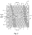
- fuel flow is introduced to the flow field from an opening at the center of one side of the fuel cell.
- a "center aisle” is arranged in the direction of flow through the opening, and is comprised of two rows of flow barriers that allow the flow to turn to both sides of the center aisle.
- the center aisle's width may vary (i.e., decrease) along the direction of flow since the amount of flow is progressively smaller as flow reaches the opposite side of the fuel cell.
- the flow field on each side of the center aisle comprises several rows of flow barriers (i.e., dimples) of circular or elliptical shapes. These barriers may be aligned or staggered, the latter providing better mixing of the flow which enhances the diffusion of fuel into the electrodes and thus promotes better cell performance.
- the flow is free to turn in opposite directions from the center aisle, and the flow exits the cell through a series of small holes in two opposite ends of the cell.
- the diameter of these holes may vary along the sides to provide more or less flow resistance and consequently, provide adequate overall flow resistance to ensure flow uniformity.
- flow exits from only one end of the fuel cell.
- the anode or cathode flow enters one end of the fuel cell and exits at the opposite end of the fuel cell, with opposite sides of the cell blocked.
- the flow barriers along the direction of flow may be in-line or staggered as described above.
- the cathode or anode flow is introduced to the flow field through a first manifold at one end of the cell, and in a variation of that design, the flow out of the cell is collected via a second manifold at the opposite end of the cell.
- variable width channels are incorporated in a serpentine flow.
- the present invention relates to a flow field forming one wall of a channel in a flow field plate of a solid oxide fuel cell, the flow field comprising a flat substrate having a patterned array of differently-shaped flow barriers projecting from the substrate into the channel.
- the invention in another aspect, relates to a flow field for use in a solid oxide fuel cell, the flow field plate comprising a plurality of flow channels, each including a flat substrate having a patterned array of differently-shaped flow barriers projecting from the substrate into the channel; wherein the differently-shaped flow barriers include round and elliptical flow barriers arranged in staggered rows in the direction of flow.
- the invention relates to a flow field plate for a solid oxide fuel cell, the plate formed with a plurality of flow channels, each flow channel decreasing in cross-sectional area in a flow direction, at least one of the channel walls provided with a patterned array of differently-shaped flow barriers projecting into the channel.
- the invention in still another aspect, relates to a solid oxide fuel cell comprising a solid oxide electrolyte sandwiched between a cathode and an anode and a pair of opposing flow field plates in operative association with the cathode and anode, respectively; the flow field plates each formed with a plurality of flow channels therein, at least one wall of which is formed with a patterned array of differently-shaped flow barriers projecting into the flow channel.
- FIG. 1 A schematic diagram of a typical solid oxide fuel cell stack is depicted in Figure 1.
- the cell 10 comprises an electrolyte-electrode assembly that includes a solid oxide electrolyte 12 sandwiched between a cathode 14 and an anode 16.
- oxidant typically air
- fuel typically hydrogen
- flow field plates 18, 20 respectively at inlets 22, 24.
- the oxidant and fuel streams exhaust from stack 10 at outlets 26, 28.
- power is delivered to a load depicted as resistor 30.
- Flow fields are incorporated into distribution or flow channels 32, 34 that are formed in the flow field plates 18, 20 for delivery of reactants directly to surfaces of cathode and anode in the outflow direction.
- the flow field 38 includes a flat substrate 40 embossed or otherwise suitably formed to include a plurality of flow barriers in the channel, opposite the cathode or anode.
- air or fuel flow (or simply, flow) is introduced to the channel 36 from an opening or inlet 42 at the center of side 44 of the channel.
- a "center aisle" 46 is formed or defined in the flow field plate 38 by a pair of rows 48, 50 of spaced, elliptically-shaped flow dimples or barriers 52 that protrude into the channel or flow path.
- the center (or flow) aisle may have a uniform or varied width along the flow direction.
- the spaces between the barriers 52 in the two center rows 48, 50 allow the flow to turn substantially 90° to both sides of the center aisle.
- Side 62 is closed, and side 44 is closed except for the presence of inlet 42. Thus, all flow is directed out of the opposite ends of the channel 36, in directions that are transverse to the direction of flow at the inlet 42.
- the flow field on each side of the center aisle 46 is made up of several rows of flow barriers 64, 66 of circular and elliptical shape, respectively.
- the flow barriers or dimples 64 that lie adjacent the center aisle 46 are rounded in shape and are staggered in the outflow direction.
- Larger, elliptical flow barriers (or ellipses) 66 have their major axes oriented parallel to the outflow direction and are also staggered in the outflow direction. Staggered barriers provide better mixing of the flow, which in turn, enhances the flow diffusion into the electrodes and promotes better fuel cell performance.
- the shape and pattern of the barriers as shown in Figure 2 is exemplary only and may be altered to suit requirements.
- Figure 3 illustrates an alternative flow field design similar to the design in Figure 2 but where the channel 68 is essentially configured as half the channel 36.
- flow is permitted to exit from only one end 70 of the channel.
- the flow enters the channel side 72 via inlet 74 and along a now-closed end 76.
- the flow is directed along the end 76 but is permitted to turn and flow in a transverse direction, toward end 70 where the flow exits through a plurality of outlets (small holes) 78.
- the flow field barriers are formed in the substrate 80 in a manner similar to the earlier described embodiment in that an inlet aisle 82 is formed by end 76 in combination with spaced elliptical flow barriers 84.
- Staggered rows of circular and elliptical dimples 86, 88, respectively, define a plurality of flow paths in a transverse or outflow direction, from the aisle 82 to the outlet holes 78.
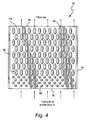
- the flow channel 90 is designed to have a substantially straight flow field. Sides 92 and 94 are closed while end 96 is open to inlet flow. Opposed end 98 is closed except for the plurality of holes or outlets 100. Between ends 96, 98, there are staggered rows of round and elliptical flow barriers 102, 104, respectively, formed in the substrate 106. Note that the smaller round flow barriers 102 are closest to the inlet while the larger elliptical flow barriers 104 are downstream of the inlet with major axes arranged parallel to the flow direction.
- the diameter of the holes 100, as well as holes 54 in Figure 2 and 78 in Figure 3, may vary to provide more or less flow resistance and, consequently, provide adequate overall flow resistance that ensures flow uniformity.
- the size, configuration and density of the flow barriers 102 and 104, as well as barriers 52, 64 and 66 in Figure 2 and 84, 86 and 88 in Figure 3, may also vary to provide the desired uniform flow for a given flow rate and required fuel cell power.
- Figure 5 illustrates yet another channel and flow field design that is similar to the channel 90 in Figure 4, but where the cathode or anode flow is introduced through a manifold.
- channel 106 includes closed sides 108, 110 and one end 112 closed except for the plurality of outlet holes 114.
- the inlet 116 is formed by a generally inverted cone-shaped wall with a centered inlet manifold 118 introducing the anode or cathode flow into the flow field.
- the latter is made up of relatively smaller, round flow barriers 120 and relatively larger elliptically-shaped flow barriers 122 formed in the substrate 124 and arranged substantially identically to the flow field in Figure 4, i.e., in staggered rows in the direction of flow.
- the channel 130 and flow field design formed in the substrate 131 is similar to the channel 112 in Figure 5 but in this case, flow is both introduced and collected by manifolds.
- the channel 130 includes closed sides 132, 134 and an inlet 136 formed by a generally inverted cone-shaped end wall with a centered inlet manifold 138 for introducing the anode or cathode flow into the channel.
- the outlet 140 is formed by a similar, cone-shaped end wall with a centered outlet manifold 142.
- Outlets 144 in an internal channel end wall 146 feed the outlet flow to the manifold. This configuration is desirable when the cathode or anode flow is reclaimed at the channel exit.
- the flow barriers 148, 150 are otherwise substantially identical in both shape and pattern to the barriers 120, 122 in Figure 5.
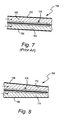
- a second feature of the invention relates to the configuration of the channels in the flow field plates, and specifically, to the gradual reduction in channel cross section designed to promote uniform performance over the entire cell.
- a known flow channel configuration is illustrated where the walls 152 and 154 of the channel 156 in combination with an anode/electrolyte/cathode assembly 158, establish uniform cross section flow paths 160, 162 for the respective anode and cathode flows.
- the flow channel 164 in accordance with an exemplary embodiment of this invention, includes a pair of walls or sides 166 and 168 on either side of a centrally-located anode/electrolyte/cathode assembly 170. Tapering at least two opposite walls of the channel in the flow direction results in flow paths 172 and 174 for the respective anode and cathode flows that reduce gradually in cross section, and thus increase the flow velocity in a downstream or flow direction.
- the flow field arrangements of Figures 2-6 may be incorporated into the channel 156, with the flow barriers formed on the internal side of walls 166, 168.
- FIG. 9 another exemplary embodiment of the invention relates to the channel configuration in a tubular fuel cell 176.
- the anode 178, electrolyte 180 and cathode 182 are formed in a C-shaped configuration, with internal flow walls 184, 186 defining an air inlet passage 188 and a pair of outlet passages 190, 192.
- the walls 184, 186 are sloped to decrease the outlet area passages in the direction of flow. The decrease in cross-sectional area increases flow velocity in the downstream direction.
- the above-described flow field barrier designs may be provided on the sides of walls 184, 186 facing the adjacent cathode.
- a channel 194 is shown that is similar to channel 176 in Figure 9, but reversed in the sense that the cathode 196, electrolyte 198 and anode 200 are arranged with internal walls 202, 204 such that air flows across the cathode and fuel flows internally through inlet passage 206 and outlet passages 208, 210, the latter decreasing in cross-sectional area in the flow direction.
- flow field plate designs may be formed on surfaces of walls 202, 204 facing the anode.
- a cell 212 is illustrated that is reduced gradually in width to thereby also increase flow velocity in a downstream direction.
- the cell 212 includes an anode flow path 224 (formed with sides 220, 222 and top 214) and a cathode flow path 226 (formed with sides 228, 230, and bottom 216) vertically stacked about an anode/electrolyte/cathode assembly 218.
- the top 214 and bottom 216 are gradually reduced in width in the direction of flow so that the flow velocity in channels 224 and 226 is increased in the downstream direction and toward a smaller area of the cell. Therefore, the fuel cell performance is expected to be higher than in a constant width channel.
- Flow field designs as described in connection with Figures 1-6 may be formed on the interior surfaces 214 and 216 facing the anode and cathode, respectively.
- Figure 12 illustrates yet another exemplary embodiment of the invention.
- the channel 232 is comprised of parallel sides 234, 236 as well as parallel ends 238, 240, and the internal walls 242, 244 and 246 are sloped relative to adjacent sides 234, 236.
- the internal walls thus create a serpentine flow path with an inlet 246 in the upper portion of side 238.
- Each section of the serpentine flow path decreases in cross section in the flow direction from one end of the cell to the other.
- This serpentine flow path may include flow barriers such as dimples or protrusions on the flat substrate 248. With increased flow velocity at downstream direction, the fuel cell performance is expected to be enhanced.
Landscapes
- Life Sciences & Earth Sciences (AREA)
- Engineering & Computer Science (AREA)
- Manufacturing & Machinery (AREA)
- Sustainable Development (AREA)
- Sustainable Energy (AREA)
- Chemical & Material Sciences (AREA)
- Chemical Kinetics & Catalysis (AREA)
- Electrochemistry (AREA)
- General Chemical & Material Sciences (AREA)
- Fuel Cell (AREA)
Applications Claiming Priority (1)
| Application Number | Priority Date | Filing Date | Title |
|---|---|---|---|
| US10/978,474 US20060093891A1 (en) | 2004-11-02 | 2004-11-02 | Flow field design for high fuel utilization fuel cells |
Publications (3)
| Publication Number | Publication Date |
|---|---|
| EP1653543A2 true EP1653543A2 (fr) | 2006-05-03 |
| EP1653543A3 EP1653543A3 (fr) | 2006-07-26 |
| EP1653543B1 EP1653543B1 (fr) | 2010-10-20 |
Family
ID=35809648
Family Applications (1)
| Application Number | Title | Priority Date | Filing Date |
|---|---|---|---|
| EP05254893A Expired - Lifetime EP1653543B1 (fr) | 2004-11-02 | 2005-08-05 | Conception de champ d'écoulement pour pile à combustible à utilisation élevée de combustible |
Country Status (7)
| Country | Link |
|---|---|
| US (1) | US20060093891A1 (fr) |
| EP (1) | EP1653543B1 (fr) |
| JP (1) | JP5166684B2 (fr) |
| KR (1) | KR20060050932A (fr) |
| CN (1) | CN100527502C (fr) |
| CA (1) | CA2516749C (fr) |
| DE (1) | DE602005024222D1 (fr) |
Cited By (4)
| Publication number | Priority date | Publication date | Assignee | Title |
|---|---|---|---|---|
| WO2008151591A1 (fr) * | 2007-06-11 | 2008-12-18 | Staxera Gmbh | Unité récurrente pour empilement de piles à combustible |
| WO2010136214A1 (fr) * | 2009-05-28 | 2010-12-02 | Ezelleron Gmbh | Pile à combustible à oxyde céramique fonctionnant à haute température |
| US8158299B2 (en) | 2005-11-30 | 2012-04-17 | Daimler Ag | Bipolar plate and fuel cell unit |
| CN113169349A (zh) * | 2018-11-28 | 2021-07-23 | 罗伯特·博世有限公司 | 用于燃料电池或电解器的分配器结构 |
Families Citing this family (25)
| Publication number | Priority date | Publication date | Assignee | Title |
|---|---|---|---|---|
| US7951501B2 (en) * | 2006-08-17 | 2011-05-31 | The Trustees Of Princeton University | Fuel cell system and method for controlling current |
| US7718298B2 (en) * | 2007-03-12 | 2010-05-18 | Gm Global Technology Operations, Inc. | Bifurcation of flow channels in bipolar plate flowfields |
| US20090011323A1 (en) * | 2007-07-05 | 2009-01-08 | General Electric Company | Solid Oxide Electrochemical Devices Having an Improved Electrode |
| US8986905B2 (en) * | 2008-11-11 | 2015-03-24 | Bloom Energy Corporation | Fuel cell interconnect |
| RU2013133143A (ru) * | 2011-01-21 | 2015-02-27 | Нинбо Инститьют Оф Матириалз Текнолоджи Энд Инжиниринг,Чайниз Экэдеми Оф Сайенсез | Батарея твердооксидных топливных элементов |
| CN104718651B (zh) * | 2012-08-14 | 2017-07-28 | 环能源公司 | 燃料电池流动沟道和流场 |
| WO2014026287A1 (fr) | 2012-08-14 | 2014-02-20 | Powerdisc Development Corporation Ltd. | Composants de pile à combustible, empilements et systèmes de piles à combustible modulaires |
| US9644277B2 (en) | 2012-08-14 | 2017-05-09 | Loop Energy Inc. | Reactant flow channels for electrolyzer applications |
| JP6298170B2 (ja) * | 2014-09-26 | 2018-03-20 | 京セラ株式会社 | セル、セルスタック装置、モジュールおよびモジュール収容装置 |
| JP6315609B2 (ja) * | 2015-10-16 | 2018-04-25 | 本田技研工業株式会社 | 燃料電池 |
| CA3016102C (fr) | 2016-03-22 | 2024-09-17 | Loop Energy Inc. | Conception de champ d'ecoulement de piles a combustible pour gestion thermique |
| CN108183247B (zh) * | 2016-12-08 | 2020-05-19 | 中国科学院大连化学物理研究所 | 一种液态流体混合器及其于直接液体燃料电池中的应用 |
| EP3783711A4 (fr) | 2018-03-30 | 2022-03-16 | Osaka Gas Co., Ltd. | Corps empilé d'éléments électrochimiques, élément électrochimique, module électrochimique, dispositif électrochimique et système d'énergie |
| CN109509896B (zh) * | 2018-12-11 | 2020-10-02 | 中国科学院大连化学物理研究所 | 一种提高燃料电池双极板波浪形流道流场有效面积的流场结构 |
| JP7241588B2 (ja) * | 2019-03-29 | 2023-03-17 | 大阪瓦斯株式会社 | 電気化学素子、電気化学モジュール、電気化学装置及びエネルギーシステム |
| JP7550560B2 (ja) | 2020-07-28 | 2024-09-13 | 大阪瓦斯株式会社 | 固体酸化物形燃料電池 |
| CN113140746A (zh) * | 2021-04-21 | 2021-07-20 | 大连海事大学 | 一种梭子鱼仿生燃料电池双极板 |
| DE102021206796A1 (de) | 2021-06-30 | 2023-01-05 | Cellcentric Gmbh & Co. Kg | Separatorplatte für eine Brennstoffzelle |
| US12586798B2 (en) | 2021-07-03 | 2026-03-24 | Cevizdere LLC | Methods and apparatus for mold mitigation in fuel cell humidifiers |
| CN113571730B (zh) * | 2021-07-28 | 2022-11-25 | 广东省武理工氢能产业技术研究院 | 一种质子交换膜燃料电池双极板流场结构 |
| EP4181243A3 (fr) * | 2021-11-12 | 2023-05-31 | Bloom Energy Corporation | Interconnexion de piles à combustible optimisée pour un fonctionnement dans un combustible à hydrogène |
| KR102865146B1 (ko) * | 2022-11-24 | 2025-09-29 | 부산대학교 산학협력단 | 평판형 고체 산화물 연료 전지의 설계 방법 및 이에 의해 설계된 고체 산화물 연료 전지 |
| CN116565247A (zh) * | 2023-04-20 | 2023-08-08 | 武汉氢能与燃料电池产业技术研究院有限公司 | 质子交换膜燃料电池流场板 |
| CN116565246A (zh) * | 2023-04-20 | 2023-08-08 | 武汉氢能与燃料电池产业技术研究院有限公司 | 燃料电池流场板 |
| WO2025028530A1 (fr) * | 2023-07-31 | 2025-02-06 | 京セラ株式会社 | Cellule électrochimique, dispositif à cellule électrochimique, module et dispositif de logement de module |
Citations (6)
| Publication number | Priority date | Publication date | Assignee | Title |
|---|---|---|---|---|
| US4988583A (en) | 1989-08-30 | 1991-01-29 | Her Majesty The Queen As Represented By The Minister Of National Defence Of Her Majesty's Canadian Government | Novel fuel cell fluid flow field plate |
| US5686199A (en) | 1996-05-07 | 1997-11-11 | Alliedsignal Inc. | Flow field plate for use in a proton exchange membrane fuel cell |
| US5840438A (en) | 1995-08-25 | 1998-11-24 | Ballard Power Systems Inc. | Electrochemical fuel cell with an electrode substrate having an in-plane nonuniform structure for control of reactant and product transport |
| US6093502A (en) | 1998-10-28 | 2000-07-25 | Plug Power Inc. | Fuel cell with selective pressure variation and dynamic inflection |
| US6099984A (en) | 1997-12-15 | 2000-08-08 | General Motors Corporation | Mirrored serpentine flow channels for fuel cell |
| US6586128B1 (en) | 2000-05-09 | 2003-07-01 | Ballard Power Systems, Inc. | Differential pressure fluid flow fields for fuel cells |
Family Cites Families (31)
| Publication number | Priority date | Publication date | Assignee | Title |
|---|---|---|---|---|
| JPS4913637A (fr) * | 1972-03-24 | 1974-02-06 | ||
| JPS57138781A (en) * | 1981-02-20 | 1982-08-27 | Hitachi Ltd | Fuel cell |
| JPS57138783A (en) * | 1981-02-20 | 1982-08-27 | Hitachi Ltd | Fuel cell |
| JPS57138782A (en) * | 1981-02-20 | 1982-08-27 | Hitachi Ltd | Fuel cell |
| JPS5830074A (ja) * | 1981-08-14 | 1983-02-22 | Hitachi Ltd | 燃料電池 |
| JPS60101380U (ja) * | 1983-12-16 | 1985-07-10 | 三洋電機株式会社 | 燃料電池のガス分離板 |
| JPS60241658A (ja) * | 1984-05-16 | 1985-11-30 | Agency Of Ind Science & Technol | 燃料電池のセパレ−タの製造方法 |
| JPS6262765U (fr) * | 1985-06-10 | 1987-04-18 | ||
| JP2569550B2 (ja) * | 1987-05-08 | 1997-01-08 | 石川島播磨重工業株式会社 | 燃料電池の温度分布改善方法 |
| JPH0163069U (fr) * | 1987-10-16 | 1989-04-24 | ||
| JPH02155171A (ja) * | 1988-12-08 | 1990-06-14 | Fuji Electric Co Ltd | 燃料電池 |
| US5108849A (en) * | 1989-08-30 | 1992-04-28 | Her Majesty The Queen In Right Of Canada, As Represented By The Minister Of National Defence In Her Britannic Majesty's Government Of The United Kingdom Of Great Britain And Northern Ireland | Fuel cell fluid flow field plate |
| JPH03266365A (ja) * | 1990-03-15 | 1991-11-27 | Nkk Corp | 固体電解質型燃料電池のセパレータ |
| JPH03289057A (ja) * | 1990-04-06 | 1991-12-19 | Hitachi Ltd | 燃料電池セパレータ |
| US5300370A (en) * | 1992-11-13 | 1994-04-05 | Ballard Power Systems Inc. | Laminated fluid flow field assembly for electrochemical fuel cells |
| US5527363A (en) * | 1993-12-10 | 1996-06-18 | Ballard Power Systems Inc. | Method of fabricating an embossed fluid flow field plate |
| CA2256276C (fr) * | 1997-12-18 | 2003-04-08 | Toyota Jidosha Kabushiki Kaisha | Pile a combustible et separateur |
| JPH11283639A (ja) * | 1998-03-27 | 1999-10-15 | Toyota Motor Corp | 燃料電池用セパレータおよび燃料電池 |
| JP4045678B2 (ja) * | 1998-12-18 | 2008-02-13 | トヨタ自動車株式会社 | 燃料電池用のセパレータ |
| JP2000195530A (ja) * | 1998-12-24 | 2000-07-14 | Aisin Takaoka Ltd | 燃料電池及びセパレータ |
| US6358639B2 (en) * | 1999-08-27 | 2002-03-19 | Plug Power Llc | Methods and kits for decontaminating fuel cells |
| JP4214674B2 (ja) * | 2000-01-14 | 2009-01-28 | トヨタ自動車株式会社 | 燃料電池用セパレータ |
| JP2001250569A (ja) * | 2000-03-06 | 2001-09-14 | Toyota Motor Corp | 燃料電池及びその集電板 |
| JP2002117870A (ja) * | 2000-10-10 | 2002-04-19 | Sony Corp | 燃料電池用フィールドプレート |
| JP2002151097A (ja) * | 2000-11-15 | 2002-05-24 | Suncall Corp | 燃料電池用セパレーター |
| CA2433034A1 (fr) * | 2001-02-27 | 2002-09-06 | Mukesh K. Bisaria | Champs d'ecoulement de fluide pour dispositifs electrochimiques |
| JP5041640B2 (ja) * | 2001-07-31 | 2012-10-03 | 株式会社日本自動車部品総合研究所 | 燃料電池用セパレータ |
| JP2003077497A (ja) * | 2001-09-06 | 2003-03-14 | Nippon Soken Inc | 燃料電池用セパレータ |
| JP3699070B2 (ja) * | 2002-08-21 | 2005-09-28 | 本田技研工業株式会社 | 燃料電池およびその運転方法 |
| JP4390513B2 (ja) * | 2003-09-24 | 2009-12-24 | 本田技研工業株式会社 | 燃料電池 |
| JP2005190710A (ja) * | 2003-12-24 | 2005-07-14 | Honda Motor Co Ltd | 燃料電池 |
-
2004
- 2004-11-02 US US10/978,474 patent/US20060093891A1/en not_active Abandoned
-
2005
- 2005-08-05 DE DE602005024222T patent/DE602005024222D1/de not_active Expired - Lifetime
- 2005-08-05 EP EP05254893A patent/EP1653543B1/fr not_active Expired - Lifetime
- 2005-08-18 CA CA2516749A patent/CA2516749C/fr not_active Expired - Fee Related
- 2005-08-31 JP JP2005250505A patent/JP5166684B2/ja not_active Expired - Fee Related
- 2005-09-01 KR KR1020050081329A patent/KR20060050932A/ko not_active Abandoned
- 2005-09-02 CN CNB2005100996846A patent/CN100527502C/zh not_active Expired - Fee Related
Patent Citations (6)
| Publication number | Priority date | Publication date | Assignee | Title |
|---|---|---|---|---|
| US4988583A (en) | 1989-08-30 | 1991-01-29 | Her Majesty The Queen As Represented By The Minister Of National Defence Of Her Majesty's Canadian Government | Novel fuel cell fluid flow field plate |
| US5840438A (en) | 1995-08-25 | 1998-11-24 | Ballard Power Systems Inc. | Electrochemical fuel cell with an electrode substrate having an in-plane nonuniform structure for control of reactant and product transport |
| US5686199A (en) | 1996-05-07 | 1997-11-11 | Alliedsignal Inc. | Flow field plate for use in a proton exchange membrane fuel cell |
| US6099984A (en) | 1997-12-15 | 2000-08-08 | General Motors Corporation | Mirrored serpentine flow channels for fuel cell |
| US6093502A (en) | 1998-10-28 | 2000-07-25 | Plug Power Inc. | Fuel cell with selective pressure variation and dynamic inflection |
| US6586128B1 (en) | 2000-05-09 | 2003-07-01 | Ballard Power Systems, Inc. | Differential pressure fluid flow fields for fuel cells |
Cited By (9)
| Publication number | Priority date | Publication date | Assignee | Title |
|---|---|---|---|---|
| US8158299B2 (en) | 2005-11-30 | 2012-04-17 | Daimler Ag | Bipolar plate and fuel cell unit |
| WO2008151591A1 (fr) * | 2007-06-11 | 2008-12-18 | Staxera Gmbh | Unité récurrente pour empilement de piles à combustible |
| AU2008261436B2 (en) * | 2007-06-11 | 2011-01-20 | Sunfire Gmbh | Repeater unit for a fuel cell stack |
| US8293424B2 (en) | 2007-06-11 | 2012-10-23 | Staxera Gmbh | Flow field unit for a fuel cell stack |
| WO2010136214A1 (fr) * | 2009-05-28 | 2010-12-02 | Ezelleron Gmbh | Pile à combustible à oxyde céramique fonctionnant à haute température |
| US9583772B2 (en) | 2009-05-28 | 2017-02-28 | Ezelleron Gmbh | Oxide-ceramic high-temperature fuel cell |
| CN113169349A (zh) * | 2018-11-28 | 2021-07-23 | 罗伯特·博世有限公司 | 用于燃料电池或电解器的分配器结构 |
| US20220029175A1 (en) * | 2018-11-28 | 2022-01-27 | Robert Bosch Gmbh | Distributor structure for a fuel cell or electrolyser |
| US12080921B2 (en) * | 2018-11-28 | 2024-09-03 | Robert Bosch Gmbh | Distributor structure for a fuel cell or electrolyser |
Also Published As
| Publication number | Publication date |
|---|---|
| CA2516749C (fr) | 2013-04-09 |
| KR20060050932A (ko) | 2006-05-19 |
| DE602005024222D1 (de) | 2010-12-02 |
| CN100527502C (zh) | 2009-08-12 |
| US20060093891A1 (en) | 2006-05-04 |
| JP5166684B2 (ja) | 2013-03-21 |
| EP1653543A3 (fr) | 2006-07-26 |
| JP2006134866A (ja) | 2006-05-25 |
| CN1770531A (zh) | 2006-05-10 |
| EP1653543B1 (fr) | 2010-10-20 |
| CA2516749A1 (fr) | 2006-05-02 |
Similar Documents
| Publication | Publication Date | Title |
|---|---|---|
| EP1653543B1 (fr) | Conception de champ d'écoulement pour pile à combustible à utilisation élevée de combustible | |
| US9761889B2 (en) | Fuel cell flow field channel with partially closed end | |
| KR101693993B1 (ko) | 연료전지용 분리판 | |
| US7867666B2 (en) | Fuel cell with triangular buffers for reactant gas and coolant | |
| WO2008094550A1 (fr) | Composants d'un empilement de pile à combustible | |
| WO2002001661A1 (fr) | Conception d'interconnecteur pour empilements de piles a combustible a oxyde solide | |
| US6852442B2 (en) | Internal fuel staging for improved fuel cell performance | |
| US9306227B2 (en) | Fuel cell and flow field plate for fluid distribution | |
| US9065088B2 (en) | Modification to stampable flowfields to improve flow distribution in the channels of PEM fuel cells | |
| EP2860805B1 (fr) | Plaque de collecteur de courant pour pile à combustible et structure d'empilement la comprenant | |
| KR102076865B1 (ko) | 연료 전지용 스택 구조물 및 그의 구성 | |
| US7485389B2 (en) | Electrochemical fuel cell stack | |
| KR20240116949A (ko) | 연료 전지 스택용 바이폴라 플레이트 | |
| KR20230068959A (ko) | 가스 균등 분배 구조가 구비된 분리판을 포함하는 연료전지 스택 | |
| JP4738411B2 (ja) | 打ち抜き加工で製造されたpem燃料電池プレート | |
| CN115275253B (zh) | 燃料电池 | |
| KR102913270B1 (ko) | 연료전지용 분리판 및 이를 포함하는 연료전지 | |
| EP4734193A1 (fr) | Ensemble plaque de distribution de gaz pour piles à combustible ou électrolyseurs et empilement de piles et système de piles à combustible le comprenant | |
| EP4354557A1 (fr) | Séparateur pour pile à combustible | |
| JP4228895B2 (ja) | 固体酸化物型燃料電池 |
Legal Events
| Date | Code | Title | Description |
|---|---|---|---|
| PUAI | Public reference made under article 153(3) epc to a published international application that has entered the european phase |
Free format text: ORIGINAL CODE: 0009012 |
|
| AK | Designated contracting states |
Kind code of ref document: A2 Designated state(s): AT BE BG CH CY CZ DE DK EE ES FI FR GB GR HU IE IS IT LI LT LU LV MC NL PL PT RO SE SI SK TR |
|
| AX | Request for extension of the european patent |
Extension state: AL BA HR MK YU |
|
| RAP1 | Party data changed (applicant data changed or rights of an application transferred) |
Owner name: GENERAL ELECTRIC COMPANY |
|
| PUAL | Search report despatched |
Free format text: ORIGINAL CODE: 0009013 |
|
| AK | Designated contracting states |
Kind code of ref document: A3 Designated state(s): AT BE BG CH CY CZ DE DK EE ES FI FR GB GR HU IE IS IT LI LT LU LV MC NL PL PT RO SE SI SK TR |
|
| AX | Request for extension of the european patent |
Extension state: AL BA HR MK YU |
|
| 17P | Request for examination filed |
Effective date: 20070126 |
|
| AKX | Designation fees paid |
Designated state(s): CH DE FR GB LI NL |
|
| 17Q | First examination report despatched |
Effective date: 20070510 |
|
| GRAP | Despatch of communication of intention to grant a patent |
Free format text: ORIGINAL CODE: EPIDOSNIGR1 |
|
| GRAS | Grant fee paid |
Free format text: ORIGINAL CODE: EPIDOSNIGR3 |
|
| GRAA | (expected) grant |
Free format text: ORIGINAL CODE: 0009210 |
|
| AK | Designated contracting states |
Kind code of ref document: B1 Designated state(s): CH DE FR GB LI NL |
|
| REG | Reference to a national code |
Ref country code: GB Ref legal event code: FG4D |
|
| REG | Reference to a national code |
Ref country code: CH Ref legal event code: EP Ref country code: CH Ref legal event code: NV Representative=s name: SERVOPATENT GMBH |
|
| REG | Reference to a national code |
Ref country code: NL Ref legal event code: T3 |
|
| REF | Corresponds to: |
Ref document number: 602005024222 Country of ref document: DE Date of ref document: 20101202 Kind code of ref document: P |
|
| PLBE | No opposition filed within time limit |
Free format text: ORIGINAL CODE: 0009261 |
|
| STAA | Information on the status of an ep patent application or granted ep patent |
Free format text: STATUS: NO OPPOSITION FILED WITHIN TIME LIMIT |
|
| 26N | No opposition filed |
Effective date: 20110721 |
|
| REG | Reference to a national code |
Ref country code: DE Ref legal event code: R097 Ref document number: 602005024222 Country of ref document: DE Effective date: 20110721 |
|
| PGFP | Annual fee paid to national office [announced via postgrant information from national office to epo] |
Ref country code: NL Payment date: 20130826 Year of fee payment: 9 Ref country code: DE Payment date: 20130828 Year of fee payment: 9 Ref country code: CH Payment date: 20130828 Year of fee payment: 9 |
|
| PGFP | Annual fee paid to national office [announced via postgrant information from national office to epo] |
Ref country code: GB Payment date: 20130827 Year of fee payment: 9 Ref country code: FR Payment date: 20130819 Year of fee payment: 9 |
|
| REG | Reference to a national code |
Ref country code: DE Ref legal event code: R119 Ref document number: 602005024222 Country of ref document: DE |
|
| REG | Reference to a national code |
Ref country code: NL Ref legal event code: V1 Effective date: 20150301 |
|
| REG | Reference to a national code |
Ref country code: CH Ref legal event code: PL |
|
| GBPC | Gb: european patent ceased through non-payment of renewal fee |
Effective date: 20140805 |
|
| PG25 | Lapsed in a contracting state [announced via postgrant information from national office to epo] |
Ref country code: NL Free format text: LAPSE BECAUSE OF NON-PAYMENT OF DUE FEES Effective date: 20150301 Ref country code: LI Free format text: LAPSE BECAUSE OF NON-PAYMENT OF DUE FEES Effective date: 20140831 Ref country code: CH Free format text: LAPSE BECAUSE OF NON-PAYMENT OF DUE FEES Effective date: 20140831 |
|
| REG | Reference to a national code |
Ref country code: FR Ref legal event code: ST Effective date: 20150430 |
|
| REG | Reference to a national code |
Ref country code: DE Ref legal event code: R119 Ref document number: 602005024222 Country of ref document: DE Effective date: 20150303 |
|
| PG25 | Lapsed in a contracting state [announced via postgrant information from national office to epo] |
Ref country code: GB Free format text: LAPSE BECAUSE OF NON-PAYMENT OF DUE FEES Effective date: 20140805 Ref country code: DE Free format text: LAPSE BECAUSE OF NON-PAYMENT OF DUE FEES Effective date: 20150303 |
|
| PG25 | Lapsed in a contracting state [announced via postgrant information from national office to epo] |
Ref country code: FR Free format text: LAPSE BECAUSE OF NON-PAYMENT OF DUE FEES Effective date: 20140901 |