EP1653767A2 - Elektroakustischer Wandler und Wandleranordnung - Google Patents
Elektroakustischer Wandler und Wandleranordnung Download PDFInfo
- Publication number
- EP1653767A2 EP1653767A2 EP05023742A EP05023742A EP1653767A2 EP 1653767 A2 EP1653767 A2 EP 1653767A2 EP 05023742 A EP05023742 A EP 05023742A EP 05023742 A EP05023742 A EP 05023742A EP 1653767 A2 EP1653767 A2 EP 1653767A2
- Authority
- EP
- European Patent Office
- Prior art keywords
- transducer
- sound
- channel
- gas flow
- surroundings
- Prior art date
- Legal status (The legal status is an assumption and is not a legal conclusion. Google has not performed a legal analysis and makes no representation as to the accuracy of the status listed.)
- Withdrawn
Links
Images


Classifications
-
- H—ELECTRICITY
- H04—ELECTRIC COMMUNICATION TECHNIQUE
- H04R—LOUDSPEAKERS, MICROPHONES, GRAMOPHONE PICK-UPS OR LIKE ACOUSTIC ELECTROMECHANICAL TRANSDUCERS; ELECTRIC HEARING AIDS; PUBLIC ADDRESS SYSTEMS
- H04R11/00—Transducers of moving-armature or moving-core type
- H04R11/04—Microphones
-
- H—ELECTRICITY
- H04—ELECTRIC COMMUNICATION TECHNIQUE
- H04R—LOUDSPEAKERS, MICROPHONES, GRAMOPHONE PICK-UPS OR LIKE ACOUSTIC ELECTROMECHANICAL TRANSDUCERS; ELECTRIC HEARING AIDS; PUBLIC ADDRESS SYSTEMS
- H04R1/00—Details of transducers, loudspeakers or microphones
- H04R1/20—Arrangements for obtaining desired frequency or directional characteristics
- H04R1/22—Arrangements for obtaining desired frequency or directional characteristics for obtaining desired frequency characteristic only
- H04R1/222—Arrangements for obtaining desired frequency or directional characteristics for obtaining desired frequency characteristic only for microphones
-
- H—ELECTRICITY
- H04—ELECTRIC COMMUNICATION TECHNIQUE
- H04R—LOUDSPEAKERS, MICROPHONES, GRAMOPHONE PICK-UPS OR LIKE ACOUSTIC ELECTROMECHANICAL TRANSDUCERS; ELECTRIC HEARING AIDS; PUBLIC ADDRESS SYSTEMS
- H04R25/00—Electric hearing aids
Definitions
- the present invention relates to an electro-acoustical transducer, and a transducer assembly comprising the transducer, which transducer is adapted to operate with a sealed sound port blocked by an air impervious member or fabric.
- the electro-acoustical transducer and transducer assembly according to the invention contain first and second gas flow channels to provide necessary static pressure compensation to internal chambers of a transducer housing.
- the invention relates to an electro-acoustical transducer comprising a transducer housing, having an inner space, and comprising:
- the gas flow channels are provided for e.g. atmospheric pressure equalization of the chambers which is desired when the transducer is subjected to changes in ambient pressure, such as from variations in its height over sea level (travelling in elevators, airplanes or the like).
- ambient pressure such as from variations in its height over sea level (travelling in elevators, airplanes or the like).
- a communication device such as a hearing aid in which a leaking sound pressure from the internal of the transducer housing could cause a disturbing feed back signal to a microphone of the communication device.
- This type of gas flow channel or channels may, as will be illustrated further below, have any of a large number of shapes and dimensions.
- the first gas flow channel facilitates gas transport between the first chamber and the surroundings and the second gas flow channel facilitates gas transport between the second chamber and the surroundings.
- each chamber may be controlled separately, by the dimensions of each channel.
- the channels may be positioned independently of each other to allow separate control of acoustical properties of each channel. This positioning may be optimized in relation to e.g. a sound pressure in the pertaining chamber so that a position may be chosen where this is the lowest (maybe also depending on a given frequency range).
- the first gas flow channel facilitates gas transport between the first chamber and the surroundings and the second gas flow channel facilitates gas transport between the first chamber and the second chamber.
- this second channel may be provided in any position in the housing, such as in the form of a small aperture in the diaphragm such as a circular vent with a diameter of between 3 and 100 ⁇ m such between 3 and 30 ⁇ m or even more preferably between 3 and 20 ⁇ m.
- the first channel When the first channel extends between a chamber and the surroundings, it may advantageously have dimensions providing a transfer function, between a sound pressure within the first chamber and a sound pressure at an opening of the first channel toward the surroundings, the transfer function comprising a low pass filter having a cut-off frequency, measured under free field conditions, of less than 100 Hz, such as less than 50 Hz, or less than 20 Hz.
- the other vent may also have this characteristic.
- the desired atmospheric pressure equalization is provided while at the same time, leakage of sound to or from the outside through the channel is prevented or limited to a frequency range below the operational frequency range of the communication device which houses the electro-acoustical transducer.
- the sound pressure at the opening of the gas flow channel toward the surroundings is normally determined under controlled circumstances, such as at a predetermined distance from that opening.
- a test of this type may be performed on a receiver or loudspeaker according to the invention by positioning a miniature microphone in a distance of e.g. 1-10 cm from the opening wherein the transducer and miniature microphone are located under simulated free field conditions such as in an anechoic test chamber or anechoic room.
- a predetermined sound pressure is generated inside the housing of the transducer by applying a predetermined electrical stimulus input signal to a motor means operatively connected to the diaphragm so as to excite the diaphragm.
- the test may be made by blocking the sound port so as to make it sound impermeable. Then, a predetermined sound pressure is provided outside the receiver, and the sound pressure entering the receiver via the ports is determined using the receiver itself.
- the sound port may be provided at a first, predetermined position of the housing and wherein one or both of the gas flow channels facilitate gas flow between a chamber and the surroundings, the channel(s) being provided at an opposite position of the housing. In that manner, any sound exiting or impinging on the sound port may have a less significant role at the positions of the channel(s).
- the opposite position may be diametrically opposite to the sound port or the channel opening(s) may be provided in side parts opposite to a side part in which the sound port is provided.
- the transducer further comprises motor means for deflecting the diaphragm in response to an electrical signal and means for providing an electrical signal to the deflecting means.
- the motor means may be based on a moving coil operation or on moving armature operation to provide a loudspeaker or sound producing transducer.
- the means for providing the electrical signal may comprise a digital or analogue power amplifier or other signal generator.
- the transducer further comprises means for providing an electrical signal corresponding to a deflection of the diaphragm and means for receiving an electrical signal corresponding to a deflection of the diaphragm.
- a microphone or a sound detecting transducer is provided.
- the means for receiving the electrical signal may then be an amplifier and/or a circuit for processing and outputting a signal correlated to the sound detected.
- the sound port is substantially impervious to gas. This may be obtained by covering the sound port with a sound transporting member, such as a thin compliant membrane, which is substantially impervious to flow of gas. Sound may be transported through the member in a substantially transparent manner by choosing a suitable flexible or deflectable fabric for the thin compliant membrane.
- a sound transporting member such as a thin compliant membrane
- This sound transporting member has the advantage that debris, dust, sweat or other liquids are unable to block the sound port or actually enter into an interior of the transducer and damage sensitive elements contained therein.
- Prior art transducers have traditionally used the sound port for static pressure compensation. However, due to the provision of gas flow channels for both chambers, this problem has been circumvented and solved in transducers according to the present invention.
- the housing may comprise an extension, such as a pipe stub, for easy attachment and positioning of the transducer to other elements of a larger assembly, such as a portable communication device, comprising the transducer.
- the sound port may then be provided in the distal end of the stub and the blocking or sealing member at any position from the sound port at the distal end to the chambers in the housing.
- one of the channels may be provided from a chamber to the internal space of the pipe stub so as to interconnect the two chambers.
- a second aspect of the invention relates to a transducer assembly comprising an electro acoustical transducer as described above and a sound transporting member adapted to transport sound between the surroundings and the sound port, wherein the sound is blocked with an element which is adapted to transport sound and is substantially impervious to gas flow.
- the sound transporting member may be provided for a number of reasons such as to transport sound to or from another part of the assembly to the sound port.
- the member may be detachably attached to the housing of the transducer and may be provided with the blocking member before or after this attachment.
- the member may comprise a thin compliant membrane or diaphragm in order to facilitate a more free positioning of the transducer in relation to the sound port.
- the member is airtight between the blocking member and the transducer.
- the blocking member may be positioned at an end of the member opposite to an end connected to the transducer.
- the blocking member comprises a wax-barrier or wax-filter.
- the blocking member is a membrane or a diaphragm.
- Alternative materials may be metals, plastics, polymers, silicone or rubbers.
- Such membranes may be a 10-100 ⁇ m film or foils of Polyethylene or Teflon.
- a third aspect of the invention relates to an electro-acoustical transducer comprising a transducer housing, having one or more side portions and an inner space, the transducer comprising:
- a plane of a side portion is a plane co-extending with that side portion. Naturally, this plane may be flat or bent in any direction or manner.
- the channel extends along the plane when a general axis of the channel is in the plane. This is in order to facilitate a channel having a length longer than the thickness of the side portion.
- the part of the channel extends within the side portion and may be defined by part of the material defining the side portion.
- the at least part of the channel may have a meandering shape in order to be able to increase a length of the channel without having to change overall dimensions of the transducer.
- the meandering shape may be a flat spring-shape or a serpent/sine-shape.
- the length, cross section and the shape of the channel defines its acoustic properties.
- Another manner of controlling the acoustic properties of the channel is to provide one or more cavities therein along the length thereof. Such cavities also affect the acoustic properties and may be used for providing a more effective (higher order) low pass filtering of sound travelling in the channel. These cavities will normally have a larger cross section than neighbouring parts of the channel.
- the cross section of the channel and/or cavities may be predetermined and may, e.g. be semicircular or have any particular shape.
- the side portion may be defined by two elements coextending in the plane, the channel being defined between the two elements.
- the provision of the channel and the cross section of the channel are made easy in that the channel may be provided simply by providing a groove in one of the elements.
- a corresponding (in shape and position) ridge may be provided in the other element so that these two elements (the ridge being positioned in the groove) will cooperate in defining the cross section of the channel.
- Punching, embossing, or injection moulding processes may be made with an impressing precision, so that the above method may be used for actually providing very narrow channels with well-defined cross sections.
- the channel at the second opening widens toward the surroundings.
- a larger exit opening out of the transducer is provided.
- a fourth aspect of the invention relates to a miniature hearing aid receiver, microphone or loudspeaker comprising an electro-acoustical transducer or an assembly as described above.
- the term miniature transducer designates a small or sub-miniature transducer such as one having an extension, in the plane of the diaphragm, of less than 7.0 x 5.0 mm or less than 5.0 mm x 4.0 mm, such as 3.5 mm x 3.5 mm, or even more preferably less than 3.0 mm x 3.0 mm.
- a miniature transducer may comprise a so-called MEMS based transducer element which is a transducer element wholly or at least partly fabricated by application of Micro Mechanical System Technology.
- the miniature transducer element may comprise a semiconductor material such as Silicon or Gallium Arsenide in combination with conductive and/or isolating materials such as silicon nitride, polycrystalline silicon, silicon oxide and glass.
- the miniature transducer element may comprise solely conductive materials such as aluminium, copper etc., optionally in combination with isolating materials like glass and/or silicon oxide.
- the transducer may be used in larger applications such as in mobile telephones or PDA's.
- a fifth aspect of the invention relates to an electro-acoustical transducer comprising a transducer housing, having an inner space, and comprising:
- the specific sound characteristics of the gas flow channel may be defined by the porous member and not the opening in the housing. Normally, very small and well-defined gas flow channels are desired, which are difficult to provide in this type of housing.
- the gas flow channel may have any desired transfer function between a sound pressure within the housing and a sound pressure at an opening of the gas flow channel toward the surroundings.
- This transfer function may be that of a low pass filter having a cut-off frequency, measured under free field conditions, of less than 100 Hz, such as less than 50 Hz, or less than 20 Hz.
- the porous member may be positioned inside the housing or on an outer surface thereof.
- the porous member is attached to the housing, such as by gluing, welding, soldering or clamping. Normally, all of the opening in the housing is covered by the porous member in order to have the porous member define the sound characteristics of the gas flow channel.
- Porous materials in general, may have a plurality of holes or channels extending in parallel or more stochastically or uncontrolled.
- the holes or channels will facilitate gas transport from one surface of the member to the other.
- the holes or channels may have the same cross section along their lengths, or the cross section thereof may vary.
- the porous member comprises a foil comprising a plurality of through going holes positioned in gas flow connection with the opening.
- the holes may be parallel and directed perpendicularly (or at least at an angle to) to a surface of the foil.
- the holes may be meandering and at least partly extend also in the plane of the foil.
- any number of holes may be provided.
- the number of holes, the thickness of the foil (the length of the holes) as well as the size (normally diameter) of the holes will take part in the definition of the sound characteristics of the gas flow channel.
- the foil has a porosity between 0.05% and 3% in a volume comprising the holes.
- This volume normally is defined as a volume delimited by a boundary rather closely encircling the holes.
- the porous member comprises a grid comprising a plurality of throughgoing holes positioned in gas flow connection with the opening.
- a grid normally is a pattern of holes or openings. These holes may, as in the first embodiment, be parallel and to an angle to a surface of the grid or may be meandering.
- the grid has between 2 and 50 holes having a radius between 1.8 ⁇ m and 30 ⁇ m.
- One grid has 2 holes with a radius of 3.5-21 ⁇ m.
- Another grid has 4 holes with a radius of 2.9-17.7 ⁇ m.
- An alternative grid has 8 holes with a radius of 2.5-14.9 ⁇ m, and yet another grid has 25 holes with a radius of 1.8-11.2 ⁇ m.
- a third embodiment is one wherein the porous member comprises a foam, a web, or a ceramic comprising a plurality of through going holes positioned in gas flow connection with the opening.
- Such types of materials define a plurality of meandering channels there through.
- the porous member has a porosity between 0.02% and 15% and a thickness, in a direction away from the opening, of between 10 ⁇ m and 300 ⁇ m.
- a moving armature electro-acoustical transducer, or receiver, 10 having a housing 12, a sound port 14, a diaphragm 16 and a driving mechanism or motor 18 for driving the diaphragm 16 via a drive rod 20.
- the drive mechanism comprises a drive coil 22 driving an armature 24 to which the drive rod 20 is connected.
- the diaphragm 16 divides an interior space into a first or front volume 30 directly connected to the sound port 14 and a second or back volume 17 that comprises the motor 18.
- the drive coil 22 is electrically connected to externally accessible terminals 26 to which an electrical signal may be provided which is subsequently transformed to a corresponding sound pressure and emitted via the sound port 14.
- the diaphragm 16 divides the inner space of the housing into two chambers 30 and 32.
- the sound port 14 is closed or blocked by a thin compliant membrane 28 which is sound transmissive but gas impermeable.
- the front volume 15 and back volume 17 are pressure equalized to the surroundings by two vents, or gas flow channels, positioned at the positions identified by numbers 34 and 36. It is seen that the chamber 32 is vented via the vent 36, the chamber 30 and the vent 34. Alternatively, the vent 36 may be provided in the diaphragm 16 or directly between the chamber 32 and the surroundings.
- a sound recipient device or microphone in accordance with the present invention would also have a front and back volume divided by a deflectable diaphragm. However, the driving mechanism or motor 18 of the receiver 10 would then be replaced with means for sensing the movement of the diaphragm.
- Figure 2 illustrates another embodiment in which an extension member 50 is connected to the housing 10, and where the extension member 50 is closed by a membrane or closing member 52 adapted to transport sound but prevent gas transport.
- the vent(s) preferably have their outlets toward the surroundings as far from the output of the sound port 14 as possible in order to minimize any sound leakage or cross talk of sound along that path.
- One position of the vent(s) is beneath an elastomeric rubber suspension or "boot" normally used in hearing aids for decoupling receiver vibrations from the shell of the hearing aid.
- An effective pipe diameter of less than 100 ⁇ m such as about 50 ⁇ m will be sufficient to compensate for normally encountered pressure variations.
- vents or gas flow channel in transducer housings.
- one or more such vents or different vents may be provided in a transducer, and a vent may still be provided interconnecting the front and back volumes so that both these volumes may be vented through a single vent to the outside of the transducer.
- Figure 3 illustrates one manner of providing a gas flow channel in the transducer housing 12.
- the gas flow channel is to be provided in a side portion or side wall 40 of the housing.
- This side portion comprises two parallel elements 42 and 44 which abut each other and there between form a channel 46 which extends in a plane of the elements 42 and 44 and the side wall 40.
- the gas flow channel 46 is connected to either the inner chamber of the housing, at opening 48 toward the interior of the housing, oro the surroundings, at opening 50.
- the opening 48 is a hole through the element 42
- the opening 50 is a hole through element 44.
- the channel 46 has a cross section and a shape defined by a groove formed in the element 44, such as by punching or embossing. It is also seen that any shape of the groove and channel may be obtained, such as a U-shaped, a spiral shaped, a sine-shaped channel or the like.
- Figure 4 illustrates another manner of providing a gas flow channel or vent where also the element 42, now denoted 42', deviates from a flat shape.
- the element 42' forms a groove into which a ridge of the element 44' extends, whereby a channel 46' is formed with a different cross section.
- the channel 46/46' preferably has a 0.1 mm diameter and a length of 6 mm. Since the acoustical resistance is proportional tohe pipe length and inversely proportional to the 4th power of the pipe diameter, increasing the diameter rapidly leads to a very long pipe for a given acoustical resistance.
- a semicircular shape is desirable in that it provides a lowest possible cut-off frequency for a maximum given dimension.
- the channel 46 may alternatively be provided by providing a flat member, such as a flat plate, a film or the like, that has, cut out therein, the channel.
- This flat member is provided between the first and second elements in which the holes are provided at the inlet and outlet of the channel, whereby the channel is formed.
- a Teflon spray may be sprayed through a shadow mask to an area corresponding to that of the channel 46 so that, when the flat member and the first/second element are glued together, the glue will not stick in the channel 46. Either the glue will not travel into the channel, or it may be removed from the channel such as by pressurized air.
- the glue may be prevented from entering the channel by a film line of polyether-urethane in much the same manner as the above Teflon spray.
- a substantially plane plate is used on the inside of the receiver top cover, so that the pipe is created by the concave shape of the cover towards the outside of the receiver due to the metal drawing process applied during manufacturing.
- this plate inside the cover will provide a thin channel.
- More such channels may be provided by providing plates at multiple surfaces of the cover. A plurality of channels in parallel has more resistance against clogging of one or more individual channels.
- FIG 5 a widening shape is illustrated which may be desired in the channel 46 at the opening toward the surroundings. In this manner, the opening will be harder to block by dust or debris. This shape is easily provided in the channel by the above production methods. In addition, it may be desired to provide this enlarged opening at a corner of the side part.
- a lateral cross-sectional view of a gas flow channel 46 comprising a number of chambers 60 along the lateral extension of the gas flow channel 46 or channels. These chambers 60 take part in the definition of the acoustical properties of the channel 46 by operating as acoustical capacitances. The inclusion of the chambers 60 will provide the channel 46 with a more effective (higher order) low pass filtering of sound travelling in the channel.
- FIG. 7 illustrates an embodiment, seen from above, the side, and from the front.
- the transducer 10 comprises a normal spout 14 and a membrane 16.
- a hole 48 is made in the top cover of the transducer 10, and a foil 45 is provided at the hole 48 and having a laser cut or edged channel 46 therein. This channel leads from the hole 48 in the cover to an opening 50 at the spout end.
- the channel 46 is closed along its length by a top cover 44.
- the dimensions of the hole 48 and the channel 46 define the acoustical properties of the gas flow channel responsible for venting the interior of the transducer 10.
- This channel construction is that it is not clogged when soldering the external terminals to the leads providing the transducer with power and/or from which electrical signals are provided or received.
- Figure 8 illustrates another embodiment in which the gas flow channel 46, which may be provided in the same manner as in figure 7, is meandering and thereby longer. It now opens 50 toward the other end of the transducer 10.
- this meandering channel 46 is that the opening 48 may be made larger without adversely affecting the properties of the venting. In addition, larger or wider channels 46 or openings 50 are less easily clogged and polluted.
- Figures 9 relates to an embodiment in which a plastic cover 49 is provided on the cover of the transducer 10 and covering the hole 48 in the cover of the transducer.
- the cover 49 three parallel channels are provided, the outer ones being filled with glue in order to fasten the cover 49 to the transducer 10 and in order to prevent gas and sound from entering or exiting the channel 46 at other positions than the hole 48 and the opening 50.
- Figure 10 illustrates a 3D model of the embodiment of figure 9, wherein the transducer 10 is seen with the cover 49 attached thereto. The opening 50 is also seen.
- this embodiment is that it is easily adaptable to existing transducers and that different covers 49 with different channels 46 and different positions of the opening 50 are easily constructed to allow a wide range of acoustical properties of the gas flow channels.
- One such type of cover, 49' is illustrated in figure 11 which illustrates an embodiment with a vent of sophisticated design and may be tailored to fit or fulfil complex acoustical filtering requirements.
- the cover 49 of figure 11 has therein a number of concentric cavities 51 and having there between round channels 46'.
- Each channel 46' has an opening toward the outer periphery thereof to the left in the figure and an opening to the inner periphery/cavity 51 at the right thereof.
- the opening 48 through the cover of the transducer 10 is positioned in the middle cavity 51.
- Gas venting from the hole 48 or aperture now firstly enters the middle cavity 51, and travels through the inner channel 46' by entering the opening at the right side of the channel 46'. The gas then travels around in the channel 46' to the left side thereof and enters the next cavity 51 where it then travels around in the cavity to the exit to the next channel 46'. This is repeated until the gas exits the outer channel 46' and is vented to the outside.
- the gas is exposed to a number of narrower channels 46' and a number of wider cavities 51 which all provide this venting with acoustical properties closely linked with the dimensions thereof.
- a wide range of desired acoustical properties may be obtained by a suitable interconnection of narrower and wider elements in the gas flow path from the (inner) hole 48 to the opening 50.
- the illustrated embodiment provides a fourth order low-pass filter by virtue of the cascade of acoustical inductances, capacitances and resistances, but clearly higher or low order low-pass filters may be constructed in suitable modification of the disclosed embodiment.
- FIG 12 an embodiment closely resembling that of figure 9 is seen.
- the cover 49 and the spout part 14 are provided as a monolithic piece which may be glued on to (or fastened in any other suitable manner) to the transducer 10, which is now of a spout-less type.
- Figure 13 illustrates another manner of positioning the hole 48 in the cover of the transducer 10.
- the hole 48 is provided in the spout 14 of the receiver 10.
- a standard receiver may be used, and the hole 48 will not be clogged when soldering the transducer.
- Figure 14 illustrates yet another position of providing the venting of the transducer 10.
- the venting is provided through the rear surface of the transducer, typically through a miniature substrate or PCB 25 which is provided for holding externally accessible solder pads or terminals 26.
- the hole 48 through the transducer wall and PCB 25 is covered by a protective grid 29, which both reduces the overall diameter of the hole 48 and which also prevents pollution and clogging of the hole 48 by ear wax, sweat etc.
- the hole 48 in the transducer wall is provided under the PCB 25 which has a channel or slit 27 inside itself or at its backside (where it is then closed between the PCB 25 and the transducer wall), which channel or slit 27 vents from the hole 48 to an opening 50 at a side of the PCB 27.
- Figure 15 illustrates yet another manner of providing venting in a receiver wherein an element 56 is positioned Inside the cover of the transducer 10 and which has a gas flow channel 58 opening into the opening 48 of the cover of the transducer at one end and opening toward the interior of the transducer 10 at the other end.
- this gas flow channel 58 may have any shape within the element 56.
- the use of the illustrated element 56 has the advantage that it does not change the outer dimensions of the transducer 10 and that it is not easily clogged. Also, the same element 56 may be used in many different transducers 10.
- FIG 16 Another embodiment is seen in figure 16, wherein the gas flow channel 46 is provided inside the cover 48 of the transducer 10.
- This gas flow channel 46 is provided by providing a channel 46 in the inner surface of the cover and covering part of this channel with a foil/plate 60 in order to close the channel 46 at a part of its length. Again, this channel 46 opens at one end into the inner volume of the transducer 10 and at the other end to the hole 48 to the surroundings.
- An advantage of this embodiment is the fact that it does not alter the outer dimensions of the transducer. It may, however, be desired to control the vibrating properties of the foil/plate 60 in order for this element to not interfere with the sound in the transducer 10.
- Figure 17 illustrates an embodiment of a transducer positioned in a hearing aid, such as in an SLA shell in an ITC or CIC hearing aid 60.
- This hearing aid comprises a cavity 65 for holding a transducer 10 having a spout 14 and an opening 48 from the inner space thereof to the surroundings.
- the shell 60 has a slit 64 which is covered by the transducer 10 to form a channel 66 in gas flow connection with the opening 48.
- This slit 64 further opens from the cavity 65 into an inner compartment 62 of the hearing aid 60 that may hold a battery and/or amplifier.
- the transducer 60 will have a gas flow channel through the inner compartment 62 which is turn is connected to the external environment through slits and opening around the movable battery compartment.
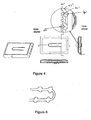
- Figure 18 illustrates an embodiment in which the venting is provided via an external element 66 having a tube providing the required characteristics of the venting.
- This tube may, e.g. be a hollow needle, such as with a length of 6 mm and a diameter of 0.1 mm.
- This tube 66 may be attached to or combined with any opening in the transducer 10, such as in the cover as seen in e.g. figure 12, provided in the PCB as seen in figure 14 or an opening provided in the spout.
- Figure 19 illustrates a quite different type of embodiment in which the opening 48 in the cover is covered by a foil 68 in which a hole much smaller than the hole 48 is provided. It is much easier to provide very small holes (see further below) in foils compared to thicker walls as those of the transducer 10. This drilling of very small holes in a foil may be made e.g. using a laser. Naturally, the foil 68 may vibrate due to the sound pressure over it, but as the hole 48 itself may be made relatively small, this vibration may be kept at an acceptable level.
- Figure 20 illustrates a transducer 10 having in its cover a plurality of smaller holes provided in a grid or suitable pattern 70.
- the number of holes defines the amount of air or gas which may flow there through and the dimensions of the holes define the acoustical characteristics of the vents.
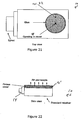
- Figure 21 illustrates an embodiment in which the hole 48 in the cover of the transducer 10 is covered by a foil or porous layer 72 glued to the cover of the transducer in order to make air venting through the hole 48 vent through the layer 72.
- the porosity of the layer 72 will determine the characteristics of the venting, independent of the diameter or size of the hole 8. This will be described further below.
- Figure 22 illustrates an even more extreme embodiment in which a whole part 12' of the cover of the transducer 10 is prepared from a porous material which, by itself and with no requirement for an actual hole therein, will facilitate the flow of gas. Again, the porosity of this material (and the thickness, volume, area etc) will determine the venting and acoustical characteristics.
- the porous material may comprise ceramics or an air permeable microporous aluminium such as METAPOR.
- ⁇ 18.6 ⁇ 10 -6 Pa.s (air viscosity coefficient @ 293 K, 10 5 Pa)
- ⁇ 1.29 kg/m 3 (mass density of air @ 293K)
- the present annex describes the calculations for a representative product.
- C is given: acoustical compliance of the combined volume of front volume and tubing up to a sound penetratable, air impervious barrier.
- the dimensions of the hole may be calculated.
- r_a ( 8 * ⁇ _air * L ) / ( n * R ⁇ 4 )
- r_a acoustic resistance
- R radius of channel
- L Length of channel
- ⁇ _air 1.81 e - 5 ( viscosity of air ) So
- the diameter of the hole therefore should be at least 8.4 [ ⁇ m] to dissipate a 10% change in pressure within 10 [s] to 10 [%].
- the hole in the receiver is about 0.3 [mm] diameter and will be covered with porous material. Since we want that the effective hole is no bigger than 50 [ ⁇ m] diameter this will require a porosity of:
- the pore size of the porous material should be considerably less than that, generally ⁇ 5 [ ⁇ m].
- Thickness of the porous material will be less than 2 [mm] to keep dimensions of the receiver small. Note that the thickness of the porous material together with the pore size defines the porosity.
- the porosity lower limit should at least be realized for that given pore size.
- a large hole may be provided in the actual transducer cover, when this is further limited (as in figure 21, for example) by a foil with the above porosity.
- R [ ( 8 ⁇ 1.81 e ⁇ 5 ⁇ 0.18 e ⁇ 3 ) / ( 3.14 ⁇ 21.24 e 9 ⁇ n ) ] ⁇ ( 1 / 4 )
- R for 8 holes minimal 2.5 [ ⁇ m]
- R defines the radius of each of the holes, not a diameter.
- the calculation relating to the grid is also valid for foams in that the overall porosity of a foam also corresponds to a number of channels with determined pore sizes. That these channels in the foam will be meandering and interacting does not affect the throughput of air to any significant degree and does also not affect the acoustic properties of the venting.
Landscapes
- Physics & Mathematics (AREA)
- Engineering & Computer Science (AREA)
- Acoustics & Sound (AREA)
- Signal Processing (AREA)
- Electromagnetism (AREA)
- Health & Medical Sciences (AREA)
- Otolaryngology (AREA)
- Electrostatic, Electromagnetic, Magneto- Strictive, And Variable-Resistance Transducers (AREA)
Priority Applications (2)
| Application Number | Priority Date | Filing Date | Title |
|---|---|---|---|
| DK11171990.2T DK2416589T3 (en) | 2004-11-01 | 2005-10-31 | Electroacoustic transducer and transducer device |
| EP11171990.2A EP2416589B1 (de) | 2004-11-01 | 2005-10-31 | Elektro-akustischer Wandler und Wandleranordnung |
Applications Claiming Priority (2)
| Application Number | Priority Date | Filing Date | Title |
|---|---|---|---|
| US62327804P | 2004-11-01 | 2004-11-01 | |
| US69659505P | 2005-07-05 | 2005-07-05 |
Related Child Applications (1)
| Application Number | Title | Priority Date | Filing Date |
|---|---|---|---|
| EP11171990.2A Division EP2416589B1 (de) | 2004-11-01 | 2005-10-31 | Elektro-akustischer Wandler und Wandleranordnung |
Publications (2)
| Publication Number | Publication Date |
|---|---|
| EP1653767A2 true EP1653767A2 (de) | 2006-05-03 |
| EP1653767A3 EP1653767A3 (de) | 2008-11-19 |
Family
ID=35705357
Family Applications (2)
| Application Number | Title | Priority Date | Filing Date |
|---|---|---|---|
| EP05023742A Withdrawn EP1653767A3 (de) | 2004-11-01 | 2005-10-31 | Elektroakustischer Wandler und Wandleranordnung |
| EP11171990.2A Expired - Lifetime EP2416589B1 (de) | 2004-11-01 | 2005-10-31 | Elektro-akustischer Wandler und Wandleranordnung |
Family Applications After (1)
| Application Number | Title | Priority Date | Filing Date |
|---|---|---|---|
| EP11171990.2A Expired - Lifetime EP2416589B1 (de) | 2004-11-01 | 2005-10-31 | Elektro-akustischer Wandler und Wandleranordnung |
Country Status (3)
| Country | Link |
|---|---|
| US (1) | US8379899B2 (de) |
| EP (2) | EP1653767A3 (de) |
| DK (1) | DK2416589T3 (de) |
Cited By (5)
| Publication number | Priority date | Publication date | Assignee | Title |
|---|---|---|---|---|
| WO2013079930A3 (en) * | 2011-12-02 | 2013-11-07 | Soundchip Sa | Electro -acoustic transducer for mounting on a substrate |
| WO2015165176A1 (zh) * | 2014-04-30 | 2015-11-05 | 中兴通讯股份有限公司 | 终端及其测距的方法 |
| US9516437B2 (en) | 2013-09-16 | 2016-12-06 | Sonion Nederland B.V. | Transducer comprising moisture transporting element |
| US11202134B2 (en) | 2016-02-29 | 2021-12-14 | Goertek Inc. | Speaker module |
| US11653154B2 (en) | 2020-08-03 | 2023-05-16 | Gn Hearing A/S | Damping filter for a hearing device |
Families Citing this family (70)
| Publication number | Priority date | Publication date | Assignee | Title |
|---|---|---|---|---|
| US8325958B2 (en) * | 2007-08-10 | 2012-12-04 | Siemens Medical Instruments Pte. Ltd. | Hearing apparatus with pressure equalization for converters |
| EP2378792A1 (de) * | 2010-04-14 | 2011-10-19 | GN Resound A/S | Hörgerät mit Schallschlauch |
| US9357287B2 (en) | 2011-07-07 | 2016-05-31 | Sonion Nederland B.V. | Multiple receiver assembly and a method for assembly thereof |
| US8983101B2 (en) | 2012-05-22 | 2015-03-17 | Shure Acquisition Holdings, Inc. | Earphone assembly |
| GB2506174A (en) | 2012-09-24 | 2014-03-26 | Wolfson Microelectronics Plc | Protecting a MEMS device from excess pressure and shock |
| EP2723102B1 (de) | 2012-10-18 | 2018-09-05 | Sonion Nederland B.V. | Wandler, Hörgerät mit dem Wandler und Verfahren zum Betrieb des Wandlers |
| DK2723098T3 (en) | 2012-10-18 | 2017-03-13 | Sonion Nederland Bv | Double transducer with common membrane |
| DK2747459T3 (en) | 2012-12-21 | 2018-12-17 | Sonion Nederland Bv | RIC unit with Thuras tube |
| DK2750413T3 (en) | 2012-12-28 | 2017-05-22 | Sonion Nederland Bv | Hearing aid |
| US9401575B2 (en) | 2013-05-29 | 2016-07-26 | Sonion Nederland Bv | Method of assembling a transducer assembly |
| EP2908551A1 (de) | 2014-02-14 | 2015-08-19 | Sonion Nederland B.V. | Verbinder für eine Empfängeranordnung |
| DK2908559T3 (en) | 2014-02-18 | 2017-01-16 | Sonion As | Process for manufacturing devices for hearing aids |
| DK2914018T3 (en) | 2014-02-26 | 2017-01-30 | Sonion Nederland Bv | Speaker, luminaire and method |
| US9247341B2 (en) * | 2014-02-26 | 2016-01-26 | Htc Corporation | Speaker module |
| US9432774B2 (en) | 2014-04-02 | 2016-08-30 | Sonion Nederland B.V. | Transducer with a bent armature |
| EP2953380A1 (de) | 2014-06-04 | 2015-12-09 | Sonion Nederland B.V. | Akustische Übersprechkompensation |
| EP3041263B1 (de) | 2014-12-30 | 2022-01-05 | Sonion Nederland B.V. | Hybridempfängermodul |
| US10009693B2 (en) | 2015-01-30 | 2018-06-26 | Sonion Nederland B.V. | Receiver having a suspended motor assembly |
| EP3057339B1 (de) | 2015-02-10 | 2020-09-23 | Sonion Nederland B.V. | Mikrofonmodul mit gemeinsamer mittlerer toneinlassanordnung |
| EP3073764B1 (de) | 2015-03-25 | 2021-04-21 | Sonion Nederland B.V. | Hörgerät mit einem einsatzelement |
| DK3073765T3 (en) | 2015-03-25 | 2022-11-14 | Sonion Nederland Bv | A receiver-in-canal assembly comprising a diaphragm and a cable connection |
| EP3133829B1 (de) | 2015-08-19 | 2020-04-08 | Sonion Nederland B.V. | Schallerzeugereinheit mit verbessertem frequenzverhalten |
| DK3139627T3 (da) | 2015-09-02 | 2019-05-20 | Sonion Nederland Bv | Høreanordning med flervejslydgivere |
| US9668065B2 (en) | 2015-09-18 | 2017-05-30 | Sonion Nederland B.V. | Acoustical module with acoustical filter |
| DK3157270T3 (da) | 2015-10-14 | 2021-06-21 | Sonion Nederland Bv | Høreaggregat med vibrationsfølsom transducer |
| DK3160157T3 (en) | 2015-10-21 | 2018-12-17 | Sonion Nederland Bv | Vibration-compensated vibroacoustic device |
| EP3177037B1 (de) | 2015-12-04 | 2020-09-30 | Sonion Nederland B.V. | Balanced armature wandler mit bistabiler balanced armature |
| EP3185584B1 (de) | 2015-12-21 | 2020-04-22 | Sonion Nederland B.V. | Receiver-anordnung mit ausgeprägter längsrichtung |
| EP3197046B1 (de) | 2016-01-25 | 2021-04-14 | Sonion Nederland B.V. | Selbstvorspannender ausgangsboosterverstärker und verwendung davon |
| EP3200479A3 (de) | 2016-01-28 | 2017-08-30 | Sonion Nederland B.V. | Elektrostatischer schallgenerator und anordnung mit elektrostatischem schallgenerator und transformator |
| EP3232685B1 (de) | 2016-04-13 | 2021-03-03 | Sonion Nederland B.V. | Kuppel für eine persönliche audio-nachrichtenvorrichtung |
| EP3252444B1 (de) | 2016-06-01 | 2023-12-20 | Sonion Nederland B.V. | Schwingungs- oder beschleunigungssensor mit anwendung von squeeze-film-dämpfung |
| EP3703389B1 (de) | 2016-08-26 | 2025-08-20 | Sonion Nederland B.V. | Vibrationssensor mit niederfrequenter dämpfungsreaktionskurve |
| EP3293985B1 (de) | 2016-09-12 | 2021-03-24 | Sonion Nederland B.V. | Hörer mit integrierter membranbewegungserkennung |
| DK3313097T3 (da) | 2016-10-19 | 2020-10-19 | Sonion Nederland Bv | An ear bud or dome |
| EP3324538A1 (de) | 2016-11-18 | 2018-05-23 | Sonion Nederland B.V. | Messschaltung mit einer verstärkerschaltung |
| US10327072B2 (en) | 2016-11-18 | 2019-06-18 | Sonion Nederland B.V. | Phase correcting system and a phase correctable transducer system |
| US20180145643A1 (en) | 2016-11-18 | 2018-05-24 | Sonion Nederland B.V. | Circuit for providing a high and a low impedance and a system comprising the circuit |
| EP3324649A1 (de) | 2016-11-18 | 2018-05-23 | Sonion Nederland B.V. | Wandler mit hoher empfindlichkeit |
| US10516947B2 (en) | 2016-12-14 | 2019-12-24 | Sonion Nederland B.V. | Armature and a transducer comprising the armature |
| EP3337191B1 (de) | 2016-12-16 | 2021-05-19 | Sonion Nederland B.V. | Schallerzeugeranordnung |
| EP3337192B1 (de) | 2016-12-16 | 2021-04-14 | Sonion Nederland B.V. | Schallerzeugeranordung |
| US10699833B2 (en) | 2016-12-28 | 2020-06-30 | Sonion Nederland B.V. | Magnet assembly |
| US10947108B2 (en) | 2016-12-30 | 2021-03-16 | Sonion Nederland B.V. | Micro-electromechanical transducer |
| EP3343956B1 (de) | 2016-12-30 | 2021-03-10 | Sonion Nederland B.V. | Schaltung und empfänger mit der schaltung |
| US10943577B2 (en) * | 2017-01-03 | 2021-03-09 | Michigan Technological University | Solid-state transducer, system, and method |
| DE112018000317T5 (de) * | 2017-01-05 | 2019-10-02 | Knowles Electronics, Llc | Lastwechseldiagnose für akustische Vorrichtungen und Verfahren |
| DK3407626T3 (en) | 2017-05-26 | 2020-07-27 | Sonion Nederland Bv | A receiver assembly comprising an armature and a diaphragm |
| DK3407625T3 (en) | 2017-05-26 | 2021-07-12 | Sonion Nederland Bv | Receiver with venting opening |
| EP3429231B1 (de) | 2017-07-13 | 2023-01-25 | Sonion Nederland B.V. | Hörgerät mit einrichtung zur vibrationsvermeidung |
| US10820104B2 (en) | 2017-08-31 | 2020-10-27 | Sonion Nederland B.V. | Diaphragm, a sound generator, a hearing device and a method |
| EP3451688B1 (de) | 2017-09-04 | 2021-05-26 | Sonion Nederland B.V. | Schallerzeuger, abschirmung und öffnung |
| GB201714956D0 (en) | 2017-09-18 | 2017-11-01 | Sonova Ag | Hearing device with adjustable venting |
| CN109672967B (zh) | 2017-10-16 | 2021-09-17 | 声扬荷兰有限公司 | 个人听力装置 |
| US10805746B2 (en) | 2017-10-16 | 2020-10-13 | Sonion Nederland B.V. | Valve, a transducer comprising a valve, a hearing device and a method |
| CN109672963B (zh) | 2017-10-16 | 2021-04-30 | 声扬荷兰有限公司 | 具有阀的声道元件和具有声道元件的换能器 |
| EP3567873B1 (de) | 2018-02-06 | 2021-08-18 | Sonion Nederland B.V. | Verfahren zur steuerung eines akustischen ventils eines hörgerätes |
| DK3531713T3 (en) | 2018-02-26 | 2023-02-06 | Sonion Nederland Bv | Miniature Speaker with Acoustical Mass |
| EP3531720B1 (de) | 2018-02-26 | 2021-09-15 | Sonion Nederland B.V. | Anordnung aus einem empfänger und einem mikrofon |
| EP3995795A1 (de) | 2018-04-30 | 2022-05-11 | Sonion Nederland B.V. | Vibrationssensor |
| DK3579578T3 (da) | 2018-06-07 | 2022-05-02 | Sonion Nederland Bv | Miniaturelydgiver |
| US10951169B2 (en) | 2018-07-20 | 2021-03-16 | Sonion Nederland B.V. | Amplifier comprising two parallel coupled amplifier units |
| DK3627856T3 (da) | 2018-09-19 | 2023-11-13 | Sonion Nederland Bv | Hus, der omfatter en sensor |
| EP4300995A3 (de) | 2018-12-19 | 2024-04-03 | Sonion Nederland B.V. | Miniaturlautsprecher mit mehreren schallhohlräumen |
| US11190880B2 (en) | 2018-12-28 | 2021-11-30 | Sonion Nederland B.V. | Diaphragm assembly, a transducer, a microphone, and a method of manufacture |
| EP3675522A1 (de) | 2018-12-28 | 2020-07-01 | Sonion Nederland B.V. | Miniaturlautsprecher ohne wesentliche akustische leckage |
| DK3726855T3 (en) | 2019-04-15 | 2021-11-15 | Sonion Nederland Bv | A personal hearing device with a vent channel and acoustic separation |
| EP3806494B1 (de) | 2019-10-07 | 2023-12-27 | Sonion Nederland B.V. | Hörgerät mit einem optischen sensor |
| KR102852670B1 (ko) | 2020-10-20 | 2025-08-28 | 주식회사 엘지에너지솔루션 | 이차 전지용 전극 및 이차 전지용 전극의 제조 방법 |
| NL2027119B1 (en) * | 2020-12-16 | 2022-07-11 | Sonion Nederland Bv | Moveable element for a transducer, transducer, in-ear device and method for determining the occurrence of a condition in a transducer |
Family Cites Families (18)
| Publication number | Priority date | Publication date | Assignee | Title |
|---|---|---|---|---|
| US388069A (en) * | 1888-08-21 | Band-saw mill | ||
| GB388069A (en) | 1929-05-15 | 1933-02-20 | Electrical Res Prod Inc | Improvements in electrodynamic devices for use in receiving or transmitting sound |
| US2958739A (en) * | 1954-08-13 | 1960-11-01 | Schalltechnik Dr Ing K Schoeps | Electroacoustic transducer |
| US4450930A (en) | 1982-09-03 | 1984-05-29 | Industrial Research Products, Inc. | Microphone with stepped response |
| DE3540106A1 (de) | 1985-11-12 | 1987-05-14 | Siemens Ag | Elektroakustischer wandler |
| US4815560A (en) * | 1987-12-04 | 1989-03-28 | Industrial Research Products, Inc. | Microphone with frequency pre-emphasis |
| US4837833A (en) * | 1988-01-21 | 1989-06-06 | Industrial Research Products, Inc. | Microphone with frequency pre-emphasis channel plate |
| NL1011733C1 (nl) * | 1999-04-06 | 2000-10-09 | Microtronic Nederland Bv | Elektroakoestische transducent met een membraan en werkwijze voor het bevestigen van een membraan in een dergelijke transducent. |
| WO2000079835A1 (de) * | 1999-06-16 | 2000-12-28 | Phonak Ag | Hinterohr-hörgerät |
| US7103196B2 (en) * | 2001-03-12 | 2006-09-05 | Knowles Electronics, Llc. | Method for reducing distortion in a receiver |
| EP1248496A3 (de) * | 2001-04-04 | 2005-11-02 | Sonionmicrotronic Nederland B.V. | Akustischer Empfänger mit verbesserter mechanischer Aufhängung |
| DE60202397T2 (de) * | 2001-05-08 | 2005-06-16 | Matsushita Electric Industrial Co., Ltd., Kadoma | Lautsprecher und Mobilendgerät |
| DE10214187C1 (de) * | 2002-03-28 | 2003-10-16 | Siemens Audiologische Technik | Lagerung eines elektroakustischen Miniaturwandlers in einem Gerät, insbesondere einem Hörhilfegerät, sowie elektroakustischer Miniaturwandler |
| US7305098B2 (en) * | 2002-05-24 | 2007-12-04 | Phonak Ag | Hearing device |
| CN1784928B (zh) * | 2003-05-09 | 2011-10-19 | 美商楼氏电子有限公司 | 用于在接收器组件中产生声能的装置和方法 |
| US7751579B2 (en) | 2003-06-13 | 2010-07-06 | Etymotic Research, Inc. | Acoustically transparent debris barrier for audio transducers |
| US7366317B2 (en) * | 2004-10-18 | 2008-04-29 | Knowles Electronics, Llc | Apparatus for creating motion amplification in a transducer with improved linkage structure |
| DK1562400T3 (da) | 2005-05-10 | 2008-11-10 | Phonak Ag | Udskiftelig hörebeskyttelsesmembran til höreapparater |
-
2005
- 2005-10-31 US US11/263,670 patent/US8379899B2/en not_active Expired - Fee Related
- 2005-10-31 DK DK11171990.2T patent/DK2416589T3/en active
- 2005-10-31 EP EP05023742A patent/EP1653767A3/de not_active Withdrawn
- 2005-10-31 EP EP11171990.2A patent/EP2416589B1/de not_active Expired - Lifetime
Non-Patent Citations (1)
| Title |
|---|
| None |
Cited By (7)
| Publication number | Priority date | Publication date | Assignee | Title |
|---|---|---|---|---|
| WO2013079930A3 (en) * | 2011-12-02 | 2013-11-07 | Soundchip Sa | Electro -acoustic transducer for mounting on a substrate |
| US9516437B2 (en) | 2013-09-16 | 2016-12-06 | Sonion Nederland B.V. | Transducer comprising moisture transporting element |
| EP2849463B1 (de) * | 2013-09-16 | 2018-04-04 | Sonion Nederland B.V. | Wandler mit Feuchtigkeitstransportelement |
| WO2015165176A1 (zh) * | 2014-04-30 | 2015-11-05 | 中兴通讯股份有限公司 | 终端及其测距的方法 |
| US11202134B2 (en) | 2016-02-29 | 2021-12-14 | Goertek Inc. | Speaker module |
| US11653154B2 (en) | 2020-08-03 | 2023-05-16 | Gn Hearing A/S | Damping filter for a hearing device |
| US12052547B2 (en) | 2020-08-03 | 2024-07-30 | Gn Hearing A/S | Damping filter for a hearing device |
Also Published As
| Publication number | Publication date |
|---|---|
| EP2416589A1 (de) | 2012-02-08 |
| EP1653767A3 (de) | 2008-11-19 |
| US8379899B2 (en) | 2013-02-19 |
| US20060109999A1 (en) | 2006-05-25 |
| DK2416589T3 (en) | 2018-03-12 |
| EP2416589B1 (de) | 2017-12-20 |
Similar Documents
| Publication | Publication Date | Title |
|---|---|---|
| EP2416589B1 (de) | Elektro-akustischer Wandler und Wandleranordnung | |
| EP3282443B1 (de) | Mems-mikrofonanordnung | |
| US9078063B2 (en) | Microphone assembly with barrier to prevent contaminant infiltration | |
| EP1653770B1 (de) | Mikrofon mit interner Dämpfung | |
| CN107872761B (zh) | 用于测量扬声器的声学特征的压力梯度麦克风 | |
| CN110800317B (zh) | 微机电系统电机和麦克风 | |
| KR102859349B1 (ko) | 마이크로 전자 기계 시스템(mems) 마이크로폰 어셈블리 | |
| US20190084828A1 (en) | Elevated mems device in a microphone with ingress protection | |
| US10779077B2 (en) | Microphone cavity | |
| CN107864696A (zh) | 具有mems声音转换器的声音转换器组件 | |
| KR20090090318A (ko) | 마이크로폰과 함께 사용하기 위한 방풍 필터 | |
| EP4167595B1 (de) | Vorrichtung und verfahren für mems-mikrofonleistung über rückvolumen | |
| EP3370431A2 (de) | Sensor mit zwei parallelen akustikfilterelementen, anordnung mit einem sensor und dem filter, tonempfänger und verfahren | |
| CN108139479A (zh) | 用于发送和/或接收声学信号的声学传感器 | |
| JP2548062Y2 (ja) | 送話器構造 | |
| EP4356619B1 (de) | Interposer zur dämpfung von mems-mikrofonen | |
| EP4258693B1 (de) | System und verfahren zur erzeugung eines audiosignals |
Legal Events
| Date | Code | Title | Description |
|---|---|---|---|
| PUAI | Public reference made under article 153(3) epc to a published international application that has entered the european phase |
Free format text: ORIGINAL CODE: 0009012 |
|
| AK | Designated contracting states |
Kind code of ref document: A2 Designated state(s): AT BE BG CH CY CZ DE DK EE ES FI FR GB GR HU IE IS IT LI LT LU LV MC NL PL PT RO SE SI SK TR |
|
| AX | Request for extension of the european patent |
Extension state: AL BA HR MK YU |
|
| PUAL | Search report despatched |
Free format text: ORIGINAL CODE: 0009013 |
|
| AK | Designated contracting states |
Kind code of ref document: A3 Designated state(s): AT BE BG CH CY CZ DE DK EE ES FI FR GB GR HU IE IS IT LI LT LU LV MC NL PL PT RO SE SI SK TR |
|
| AX | Request for extension of the european patent |
Extension state: AL BA HR MK YU |
|
| 17P | Request for examination filed |
Effective date: 20090519 |
|
| 17Q | First examination report despatched |
Effective date: 20090619 |
|
| AKX | Designation fees paid |
Designated state(s): AT BE BG CH CY CZ DE DK EE ES FI FR GB GR HU IE IS IT LI LT LU LV MC NL PL PT RO SE SI SK TR |
|
| 111Z | Information provided on other rights and legal means of execution |
Free format text: AT BE BG CH CY CZ DE DK EE ES FI FR GB GR HU IE IS IT LT LU LV MC NL PL PT RO SE SI SK TR Effective date: 20110331 |
|
| DAC | Divisional application: reference to earlier application (deleted) | ||
| STAA | Information on the status of an ep patent application or granted ep patent |
Free format text: STATUS: THE APPLICATION IS DEEMED TO BE WITHDRAWN |
|
| 18D | Application deemed to be withdrawn |
Effective date: 20120524 |