EP1653772A1 - Gehäuse mit einlage-anschluss und piezoelektrischer elektroakustischer wandler mit diesem gehäuse, prozess zur gehäuseherstellung mit einlageanschluss - Google Patents
Gehäuse mit einlage-anschluss und piezoelektrischer elektroakustischer wandler mit diesem gehäuse, prozess zur gehäuseherstellung mit einlageanschluss Download PDFInfo
- Publication number
- EP1653772A1 EP1653772A1 EP04747563A EP04747563A EP1653772A1 EP 1653772 A1 EP1653772 A1 EP 1653772A1 EP 04747563 A EP04747563 A EP 04747563A EP 04747563 A EP04747563 A EP 04747563A EP 1653772 A1 EP1653772 A1 EP 1653772A1
- Authority
- EP
- European Patent Office
- Prior art keywords
- terminal
- case
- groove
- insert
- depression
- Prior art date
- Legal status (The legal status is an assumption and is not a legal conclusion. Google has not performed a legal analysis and makes no representation as to the accuracy of the status listed.)
- Granted
Links
Images




Classifications
-
- H—ELECTRICITY
- H04—ELECTRIC COMMUNICATION TECHNIQUE
- H04R—LOUDSPEAKERS, MICROPHONES, GRAMOPHONE PICK-UPS OR LIKE ACOUSTIC ELECTROMECHANICAL TRANSDUCERS; ELECTRIC HEARING AIDS; PUBLIC ADDRESS SYSTEMS
- H04R31/00—Apparatus or processes specially adapted for the manufacture of transducers or diaphragms therefor
- H04R31/006—Interconnection of transducer parts
-
- H—ELECTRICITY
- H04—ELECTRIC COMMUNICATION TECHNIQUE
- H04R—LOUDSPEAKERS, MICROPHONES, GRAMOPHONE PICK-UPS OR LIKE ACOUSTIC ELECTROMECHANICAL TRANSDUCERS; ELECTRIC HEARING AIDS; PUBLIC ADDRESS SYSTEMS
- H04R1/00—Details of transducers, loudspeakers or microphones
- H04R1/06—Arranging circuit leads; Relieving strain on circuit leads
-
- H—ELECTRICITY
- H04—ELECTRIC COMMUNICATION TECHNIQUE
- H04R—LOUDSPEAKERS, MICROPHONES, GRAMOPHONE PICK-UPS OR LIKE ACOUSTIC ELECTROMECHANICAL TRANSDUCERS; ELECTRIC HEARING AIDS; PUBLIC ADDRESS SYSTEMS
- H04R17/00—Piezoelectric transducers; Electrostrictive transducers
Definitions
- the present invention relates to an insert terminal-containing case and a piezoelectric electroacoustic transducer using the case.
- piezoelectric electroacoustic transducers such as a piezoelectric sounder and a piezoelectric receiver that produce alarm sounds and operation sounds, have been widely used in electronic devices, household electric appliances, mobile phones, or the like.
- An exemplary piezoelectric electroacoustic transducer includes a piezoelectric diaphragm placed in an insert terminal-containing case and bonded with the insert terminal-containing case without an air leakage; and a cover having a sound-emitting hole, the cover being bonded to an opening at the upper portion of the case.
- piezoelectric diaphragms are a unimorph piezoelectric diaphragm in which a piezoelectric component composed of a piezoceramic is bonded to a surface of a metal plate.
- piezoelectric diaphragms is a bimorph piezoelectric diaphragm including a laminated piezoceramic.
- Fig. 15 shows an example of a piezoelectric electroacoustic transducer described in Patent Document 1, the transducer including a case 40, a piezoelectric diaphragm 42 contained in the case 40, and terminals 43 provided on the case 40 by insert molding.
- a supporting portion 45 is provided at the inner periphery of the case 40.
- the piezoelectric diaphragm 42 is supported by the supporting portion 45.
- An elastic insulant 48 covers edges of the piezoelectric diaphragm 42.
- a conductive adhesive 46 is applied on the insulant 48 to electrically connect the piezoelectric diaphragm 42 with the terminal 43.
- Patent Document 1 Japanese Unexamined Patent Application Publication No. 2003-58166
- the terminal 43 needs to be exposed at the inside of the case 40 by a predetermined length.
- the dimension S of the piezoelectric diaphragm 42 must be reduced by the exposed length of the terminal 43 compared with the opening dimension L.
- Miniaturization of the case 40 means a reduction in the dimension S of the piezoelectric diaphragm 42.
- the reduction in the dimension S of the piezoelectric diaphragm 42 increases its resonance frequency, which causes a reduction in sound pressure, and is thus undesirable. Therefore, to reduce the resonance frequency and increase the sound pressure, it is important to achieve the minimum difference between the opening dimension L of the case 40 and the dimension S of the piezoelectric diaphragm 42.
- an object of the present invention to provide an insert terminal-containing case capable of achieving the minimum difference between the opening dimension of the case and the dimension of the piezoelectric diaphragm, and a piezoelectric electroacoustic transducer using the case. It is another object of the present invention is to provide a process for producing an insert terminal-containing case, the process being capable of molding the case without using a complicated die, such as a sliding die and preventing the deformation of a terminal due to a pressure exerted during molding.
- the present invention provides an insert terminal-containing case including a bottom wall, four side walls, and an opening at the upper portion, wherein a terminal composed of a metal plate is vertically fixed to at least one side wall among the walls by insert molding, a groove is vertically provided at the outer side surface of the side wall fixing the terminal, the groove extending downward, the outer side surface of the terminal is partially exposed at the groove, and the inner side surface opposite the outer side surface of the terminal is partially exposed at the inner side surface of the side wall.
- the terminal composed of the metal plate is vertically fixed at the side wall of the case by insert molding, and the inner side surface of the terminal is exposed at the inner side surface of the side wall.
- the terminal When the terminal is provided at the side wall of the case by insert molding, it is necessary to prevent the deformation of the terminal due to a pressure exerted during molding. Accordingly, both inner and outer side surfaces of the terminal is held by a projection provided at a lower die and part of an upper die, thus preventing the deformation of the terminal due to a pressure exert during molding and surely exposing the terminal at the inner side surface of the side wall.
- the terminal can be provided by insert molding using only the upper and lower dies without using a complicated die, such as a sliding die.
- the die has a simple structure, the molding time can be reduced, and many insert terminal-containing cases are easily produced at the same time.
- the groove corresponding to the projection of the lower die is provided at the outer side surface of the side wall of the case.
- the groove may be provided at not the outer side surface of the side wall of the case but the inner side surface.
- the thickness at the upper end of the side wall having the groove of the case must be identical to that of the terminal.
- a thin metal plate having a thickness of, for example, about 0.1 mm is used as the terminal.
- the thickness of the resin case is about 0.1 mm, mechanical strength is insufficient.
- a bonding area required for bonding a cover or the like cannot be ensured.
- providing the groove extending downward at the outer side surface of the side wall can ensure a predetermined thickness at the upper end of the side wall, thus resolving the above-described problems.
- a cutout for exposing the outer side surface of the terminal may be provided in the vicinity of the bottom of the outer side surface of the side wall, the area of the terminal exposed at the cutout being greater than that of the terminal exposed at the groove, wherein the lower end of the groove may be run to the cutout.
- the terminal is preferably exposed at the outer side surface of the side wall of the case in a predetermined range because a solder fillet is provided for mounting a circuit substrate or the like.
- the groove is provided inevitably to hold the outer side surface of the terminal during insert molding and preferably has the shortest possible length.
- the cutout for exposing the terminal at the outer side surface of the side wall of the case is provided, the lower end of the groove is run to the cutout. As a result, it is possible to shorten the length of the groove and to suppress a reduction in the strength of the case.
- the upper end of the groove is preferably terminated at a position lower than the position of the upper end of the terminal.
- the upper end of the groove may be disposed at a position equal to or higher than that of the upper end of the terminal.
- a power for holding the upper end of the terminal is insufficient.
- the terminal is easily deformed inward or outward.
- disposing the upper end of the groove at a position lower than that of the upper end of the terminal permits the outer side surface of the upper end of the terminal to be held by the resin portion of the case, thus preventing the inward or outward deformation of the terminal.
- the insert terminal-containing case according to the present invention is preferably applied to a piezoelectric electroacoustic transducer.
- the dimension of the piezoelectric diaphragm is preferably brought close to the opening dimension of the case from the standpoint of lowering the resonance frequency of the piezoelectric diaphragm and increasing the sound pressure.
- the terminal is exposed at the inner surface of the side wall in the longitudinal direction which is perpendicular to the piezoelectric diaphragm. Therefore, it is possible to reduce the gap between the piezoelectric diaphragm and the side wall of the case and to lower the frequency and to strengthen the sound pressure of the piezoelectric diaphragm.
- a process for producing an insert terminal-containing case including the steps of preparing an upper die having a projection for forming the inner surface of a case and a lower die having a depression for forming the external surface of the case; disposing the base plate portion of an L-shaped terminal on the bottom surface of the depression of the lower die, the terminal being composed of a metal plate, and then clamping the upper and lower dies in a manner such that the standing portion of the terminal is held between the outer side surface of the projection of the upper die and the inner side surface of the depression of the lower die; injecting a resin into a cavity provided between the projection of the upper die and the depression of the lower die, and then curing the resin; and separating the upper and lower dies after curing the resin to take the case out.
- a protruding stripe is provided on the inner side surface of the depression of the lower die, the upper end of the protruding stripe being disposed at a position lower than the position of the upper end of the standing portion of the terminal, and the lower end of the protruding stripe extending to the bottom surface of the depression.
- arm portions are provided on the standing portion of the terminal, each arm portion extending from each side of the standing portion of the terminal, and in the clamping step, both front and back surfaces of the arm portions are held between the outer side surface of the projection of the upper die and the inner side surface of the depression of the lower die. Therefore, the terminal can be exposed at only in the vicinity of the corner of the inner surface of the case.
- the terminal is longitudinally fixed at the side wall of the case by insert molding and the inner side surface of the terminal is exposed at the inner side surface of the side wall. Therefore, when the piezoelectric diaphragm is provided in the case, it is possible to bring the side wall of the case close to the periphery of the piezoelectric diaphragm and to reduce the dimensional difference between the case and the piezoelectric diaphragm. As a result, it is possible to lower the resonance frequency of the piezoelectric diaphragm and to strengthen the sound pressure.
- the groove extending vertically downward is provided at the outer side surface of the side wall having the terminal of the case, the outer side surface of the terminal is partially exposed at the groove, and the inner side surface opposite the outer side surface of the terminal exposed at the groove is partially exposed at the inner side surface of the side wall. Therefore, when the terminal is provided by insert molding, it is possible to hold both inner and outer side surfaces of the terminal by the upper and lower dies, to prevent the deformation of the terminal due to a pressure exert during molding, and to surely expose the terminal at the inner side surface of the side wall.
- a resin is injected while the standing portion of the terminal is hold between the outer side surface of the projection of the upper die and the inner side surface of the depression of the lower die. Therefore, it is possible to provide the terminal by insert molding using only the upper and lower dies without using a sliding die.
- the die has a simple structure, thereby resulting in low cost and reducing the molding time. Furthermore, many insert terminal-containing cases are easily produced at the same time.
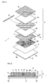
- Figs. 1 to 4 each show an example of a piezoelectric electroacoustic transducer, such as a piezoelectric sounder, using a case according to the present invention.
- This piezoelectric sounder includes a piezoelectric diaphragm 1, a case 20, and a cover 30.
- the case 20 and the cover 30 constitute a cabinet.
- the piezoelectric diaphragm 1 in this Example includes a substantially square metal plate 2, an insulating layer 3 on the entire surface of the metal plate 2, and a substantially square piezoelectric component 4 smaller than the metal plate 2.
- the piezoelectric component 4 is bonded on the insulating layer 3.
- the metal plate 2 is preferably composed of a material having spring resilience, for example, phosphor bronze, 42Ni, or the like.
- the insulating layer 3 may be a resin coating composed of, for example, a polyimide or an epoxy. Alternatively, the insulating layer 3 may be an oxide film prepared by performing an oxidizing treatment.
- the piezoelectric component 4 is formed by laminating two green sheets to be piezoceramic layers 4a and 4b with an internal electrode 5 therebetween and then co-firing the resulting laminate.
- External electrodes 6 and 7 are provided on substantially the entire front and back surfaces of the piezoelectric component, respectively. As represented by arrows P in Fig. 6, the piezoceramic layers 4a and 4b are oppositely polarized in the thickness direction.
- One side of the internal electrode 5 is exposed at an end of the piezoelectric component 4, but the opposite side is terminated at a specified distance away from an end of the piezoelectric component 4.
- the external electrodes 6 and 7 on the front and back surfaces of the piezoelectric component 4 are connected to each other via one end electrode 8.
- the internal electrode 5 is connected to interconnecting electrodes 10 and 11 on the front and back surfaces, respectively, via the other end electrode 9.
- Each of the interconnecting electrodes 10 and 11 is a small electrode provided at the middle of a side of the piezoelectric component 4 along the side and is electrically separated from the external electrodes 6 and 7 at the front and back surfaces.
- the end electrode 8 has a length corresponding to the length of a side of the piezoelectric component 4.
- the other end electrode 9 has a length corresponding to the length of the interconnecting electrodes 10 and 11.
- the interconnecting electrodes 10 and 11 are provided at both front and back surfaces, respectively, so that the piezoelectric component 4 is nondirectional. Thus, the interconnecting electrode 11 may be omitted.
- each of the interconnecting electrodes 10 and 11 may have a length corresponding to the length of a side of the piezoelectric component 4.
- the back surface of the piezoelectric component 4 is bonded on the middle of the upper surface of the insulating layer 3 with an adhesive 12 such as an epoxy adhesive (see Fig. 5).
- the metal plate 2 has a size greater than that of the piezoelectric component 4.
- the insulating layer 3 continuously extends to the surface of an extended portion 2a extending outwardly more than the piezoelectric component 4.
- the case 20 is composed of a resin.
- the case 20 has a substantially square box shape and includes a bottom wall 20a and four side walls 20b to 20e.
- a heat-resistant resin such as a liquid-crystalline polymer (LCP), a syndiotactic polystyrene (SPS), or a polyphenylene sulfide (PPS) is preferably used as a material constituting the case.
- a supporting portion 21 for supporting the diaphragm 1 on the entire perimeter thereof is provided on the inner surface of the side walls 20b to 20e of the case 20.
- Internal connecting portions 22a and 23a of terminals 22 and 23 are exposed at the inner side surfaces of two side walls 20b and 20d that are opposite each other, the terminals 22 and 23 being electrically connected to the front-side external electrode 6 and the interconnecting electrode 10 of the diaphragm 1, respectively.
- Partitioning portions 24 are provided between the supporting portion 21 and the internal connecting portions 22a and 23a of the terminals 22 and 23, the partitioning portions 24 being formed integrally with the case 20 (see Fig. 4).
- the partitioning portions 24 function as spacers for preventing the metal plate 2 from being in contact with the terminals 22 and 23 when the metal plate 2 is placed on the supporting portion 21 as described below.
- the terminals 22 and 23 are formed in the case 20 by insert moiding and are each composed of, for example, a metal plate, such as phosphor bronze, having a thickness of about 0.1 mm.
- the internal connecting portions 22a and 23a of the terminals 22 and 23 integrally formed by punching a hoop material 29 are bent perpendicularly upward, and these bent portions serve as internal connecting portions connected to the diaphragm 1.
- the internal connecting portions 22a and 23a do not extend inside the case 20.
- External connecting portions 22b and 23b of the terminals 22 and 23 extend inside along the bottom face of the case 20.
- a wide cutout 27 is provided nearer the bottom face, and narrow grooves 28 are provided at the upper end of the cutout 27, the narrow grooves 28 extending longitudinally. The lower end of each groove 28 is run to the cutout 27.
- the terminals 22 and 23 are partially exposed at the grooves 28.
- the inner side surfaces, specifically internal connecting portions 22a and 23a, opposite the outer side surfaces of the terminals 22 and 23 exposed at the grooves 28 are partially exposed at the inner side surface of the side walls 20b and 20d.
- each groove 28 is terminated at a position being lower than the position of the upper end of each of the terminals 22 and 23 by a dimension of ⁇ . That is, the outer side surfaces of the upper ends of the terminals 22 and 23 are covered with the side walls 20b and 20d. Thus, the upper ends of the terminals 22 and 23 are held from their outer sides, thereby preventing outward and inward deformations of the terminals 22 and 23.
- the side walls 20b and 20d each have a thickness of D greater than those of the terminals 22 and 23, thereby ensuring the strength of the case 20 and an area required for bonding the cover 30 to the case 20.
- a lower sound-emitting hole 25 is provided at the bottom of one side wall 20e, in which the terminals 22 and 23 are not provided, of the case 20.
- a groove 26 for emitting sound is provided at the top of the other side wall 20c.
- the cover 30 in this Example is composed of the same material as that of the case 20 and has a flat shape. By bonding the cover 30 onto the top of the side walls of the case 20 with an adhesive 31, the groove 26 becomes an upper sound-emitting hole.
- the cover 30 has not necessarily the flat shape but may have a cap shape having a concave in cross-section.
- the upper sound-emitting hole 26 is not necessarily the groove provided at the top of the side wall of the case 20 but may be a hole provided in the cover 30.
- the piezoelectric diaphragm 1 is disposed in the case 20 in a manner such that the metal plate 2 faces the bottom wall, and the periphery of the metal plate 2 is placed on the supporting portion 21.
- an insulating material 32 is applied to the area between the periphery of the metal plate 2 and the internal connecting portions 22a and 23a of the terminals 22 and 23 in a line shape, and is then cured. Any insulating adhesive may be used as the insulating material 32, but an elastic adhesive, such as a urethane adhesive or a silicone adhesive, is preferably used.
- the conductive adhesive 33 is applied to areas between the front-side external electrode 6 and the internal connecting portion 22a of the terminal 22 and between the interconnecting electrode 10 and the internal connecting portion 23a of the terminal 23, the conductive adhesive 33 being applied perpendicular to the insulating material 32, and is then cured.
- the internal connecting portions 22a and 23a of the terminals 22 and 23 are disposed perpendicularly and are exposed in large areas. Thus, areas being in electrical contact with the conductive adhesive 33 are large, and electrical contact reliability is high.
- the conductive adhesive 33 is preferably an elastic adhesive, such as a urethane adhesive, containing a conductive filler. The conductive adhesive 33 is applied onto the metal plate 2.
- the insulating layer 3 is provided on the metal plate 2 in advance, and the periphery of the metal plate 2 is covered with the insulating material 32, the conductive adhesive 33 is not brought into direct contact with the metal plate 2.
- the entire perimeter of the metal plate 2 is fixed to the case 20 with an adhesive 34.
- Any one of known insulating adhesives may be used as the adhesive 34 but is preferably an elastic adhesive, such as a urethane adhesive or silicone adhesive.
- the cover 30 is bonded to the opening at the upper portion of the case 20 with the adhesive 31.
- the electrodes of the diaphragm 1, namely front-side external electrode 6 and interconnecting electrode 10, are connected to the electrodes of the case 20, namely terminals 22 and 23, with the conductive adhesive 33, thus improving electrical reliability compared with the case of an electrical contact via the metal plate 2.
- the conductive adhesive 33 can be coated from above the case 20 with a coater, such as a dispenser. Therefore, automation is easily achieved, and production efficiency and quality can be improved compared with those in the case in which a lead is bonded by soldering.
- the internal connecting portions 22a and 23a of the terminals 22 and 23 are exposed at the inner side surfaces of the side walls of the case 20 and are disposed perpendicular to the bottom surface of the case or diaphragm 1, the internal connecting portions 22a and 23a do not extend inside the case 20. Therefore, the dimension S of the piezoelectric diaphragm 1 can be brought close to the opening dimension L of the case 20 at a maximum. As a result, even if the opening dimension L of the case is a constant, it is possible to enlarge the dimension S of the piezoelectric diaphragm 1, thereby lowering the resonance frequency and increasing the sound pressure.
- Fig. 10 shows a process of insert-molding the terminals 22 and 23 into the case 20.
- FIG. 10 shows a state in which an upper die 35 and a lower die 36 are clamped, and (b) shows a state in which the upper die 35 and the lower die 36 are detached.
- the upper die 35 includes a projection 35a for forming the inner surface of the case 20, and a portion 35b, which is part of the side surface of the projection 35a, protruding outward.
- the lower die 36 includes a depression 36a for forming the outer surface of the case 20, and a protruding portion 36b is provided at part of the side surface of the depression 36a, the protruding portion 36b protruding inside.
- the upper end of the protruding portion 36b is disposed at a position lower than the position of the upper end of the standing portion 22a, described below, of the terminal 22.
- the lower end of the protruding portion 36b extends the bottom surface of the depression 36a.
- a cavity is formed between the projection 35a and the depression 36a.
- the terminal 22 that is formed into an L shape is disposed between the upper and lower dies 35 and 36, and then the dies are clamped.
- the bottom plate portion 22b namely the external connecting portion, of the terminal 22 is disposed on the bottom surface of the depression 36a of the lower die 36.
- both front and back surfaces of the standing portion 22a of the terminal 22 are held by the portion 35b, which is part of the projection 35a of the upper die 35, and the protruding portion 36b of the depression 36a of the lower die 36, thus preventing the deformation of the standing portion 22a of the terminal 22 due to the injection pressure of a resin.
- the upper and lower dies 35 and 36 are detached vertically.
- the inside space of the case 20 is formed by the projection 35a of the upper die 35.
- the outer surface of the case 20 is formed by the depression 36a of the lower die 36.
- the cutout 27 and the grooves 28 are formed by the protruding portion 36b of the depression 36a.
- the standing portion 22a, namely the internal connecting portion, of the terminal 22 can be exposed at the inside of the side wall 20b of the case 20.
- Fig. 16 shows Comparative Example of a piezoelectric electroacoustic transducer compared with that of the present invention.
- a terminal 53 is provided in a case 50, and the internal connecting portion 53a of the terminal 53 is exposed at the inner side surface of the side wall 51 of the case 50.
- a supporting portion 52 is provided at the inner side of the side wall 51 of the case 50.
- a piezoelectric diaphragm 54 is placed on the supporting portion 52.
- the piezoelectric diaphragm 54 is fixed to the case 50 with an elastic adhesive 55.
- the internal connecting portion 53a of the terminal 53 is electrically connected to the piezoelectric diaphragm 54 with a conductive adhesive 56.
- Fig. 17 shows a situation when the terminal 53 is provided in the case 50 with an upper die 60 and a lower die 61 by insert molding.
- a resin flows in the direction represented by an arrow.
- the standing portion, specifically internal connecting portion 53a of the terminal 53, may be deformed outward because of the pressure of the resin flow, and, in some cases, the terminal 53 is not exposed at the inner side of the side wall 51.
- Fig. 18 there may be a process of performing insert molding using a sliding die 62.
- Fig. 18 shows a state when insert molding is performed.
- b shows a state when the sliding die is detached.
- c shows a state when the upper and lower dies are detached.
- the process using the sliding die 62 has the following disadvantages: the occurrence of time loss due to a sliding operation, complicated and expensive dies, the difficulty of the production of a high-density multi-cavity mold, and high cost.
- Example 1 As shown in Example 1, as shown in Fig. 10 (a), since both front and back surfaces of the standing portion 22a of the terminal 22 is held by the portion 35b, which is part of the projection 35a of the upper die 35, and the protruding portion 36b of the depression 36a of the lower die 36, it is possible to prevent the deformation of the standing portion 22a of the terminal 22 due to the injection pressure of a resin. Therefore, it is possible to prevent the deformation of the terminal due to the pressure in molding without using the sliding die.
- Figs. 11 to 13 each show Example 2 of a case according to the present invention.
- the same reference numeral represents the same portion in Example 1 (Figs. 1 to 10). Redundant description is not repeated.
- Example 1 the piezoelectric diaphragm 1 is supported at the middle of each of two sides of the case 20 with the insulating materials 32 and the conductive adhesive 33, the two sides being opposite each other. In some cases, the piezoelectric diaphragm 1 is preferably supported in the vicinity of the corners depending on the vibrating characteristics of the piezoelectric diaphragm 1. Accordingly, in this example, the internal connecting portions 22a and 23a of the terminals 22 and 23 (see Figs.
- Arm portions 22c are provided at the standing portions of the terminals 22 and 23 in the side walls 20b and 20d of the case 20, each of the arm portions 22c extending in the transverse direction.
- a pair of grooves 28 is provided at the outer side surfaces of the side walls 20b and 20d of the case 20, each of the grooves 28 extending vertically downward, and the outer side surfaces corresponding to the arm portions 22c.
- each of the cutouts 27 for exposing the outer side surfaces of the standing portions of the terminals 22 and 23 is separately provided at the middle between the pair of grooves 28.
- Tapered surfaces 24a each inclined inward are provided at the inner side surfaces of the side walls 20b and 20d of the case 20. Cutouts 24b for partially exposing the arm portions 22c and 23c, i.e., the cutouts 24b for exposing the internal connecting portions 22a and 23a, are provided at the two positions of each of the tapered surfaces 24a. Since the internal connecting portions 22a and 23a are each disposed at a position outward of the tapered surface 24a, it is possible to prevent the direct contact between the metal plate 2 and the terminals 22 and 23 when the piezoelectric diaphragm 1 is placed on the supporting portion 21. Furthermore, the tapered surfaces 24a function as guiding surfaces when placing the piezoelectric diaphragm 1 in the case 20.
- two internal connecting portions 22a of the terminal 22 and two internal connecting portions 23a of the terminal 23 are exposed at the inner side surfaces, namely tapered surfaces 24a, of the side walls 20b and 20d, respectively, of the case 20.
- single internal connecting portion 22a and single internal connecting portion 23a may be exposed at the inner side surfaces of the side walls 20b and 20d, respectively.
- Fig. 14 shows a process of insert-molding the terminals 22 and 23 into the case 20 in Example 2.
- FIG. 14 shows a state in which an upper die 35 and a lower die 36 are clamped, and (b) shows a state in which the upper die 35 and the lower die 36 are detached.
- the upper die 35 includes the projection 35a for forming the inner surface of the case 20.
- the side surface 35c of the projection 35a has a tapered shape.
- a protruding portion 35b protruding outward is provided at part of the side surface.
- the protruding portion 35b corresponds to the cutout 24b.
- the lower die 36 includes the depression 36a for forming the outer surface of the case 20.
- the protruding portion 36b is provided at part of the side surface of the depression 36a, the protruding portion 36b protruding inside.
- the protruding portion 36b corresponds to the groove 28.
- another protruding portion (not shown) corresponding to the cutout 27 other than the protruding portion 36b is also provided.
- the top end of the protruding portion 36b is disposed at a position lower than the position of the upper end of the arm portion 22c of the terminal 22.
- the lower end of the protruding portion 36b extends to the bottom surface of the depression 36a.
- a cavity is formed between the projection 35a and the depression 36a.
- the terminal 22 that is formed into an L shape is disposed between the upper and lower dies 35 and 36, and then the dies are clamped.
- the bottom plate portion 22b, namely external connecting portion, of the terminal 22 is disposed on the bottom surface of the depression 36a of the lower die 36.
- both front and back surfaces of the internal connecting portion 22a of the terminal 22 are held by the protruding portion 35b of the upper die 35 and the protruding portion 36b of the lower die 36, thus preventing the deformation of the internal connecting portion 22a of the terminal 22 due to the injection pressure of a resin.
- the upper and lower dies 35 and 36 are detached vertically.
- the inside space of the case 20 is formed by the projection 35a of the upper die 35.
- the outer surface of the case 20 is formed by the depression 36a of the lower die 36.
- the groove 28 is formed by the protruding portion 36b of the lower die 36.
- the tapered surface 24a is formed by the side surface 35c of the projection 35a of the upper die 35.
- the cutout 24b is formed by the projection 35a.
- the piezoelectric diaphragm 1 in the examples has a structure in which a laminated piezoelectric component 4 is bonded to a metal plate.
- the piezoelectric component is not limited to have a laminated structure but may have a single-plate structure.
- the piezoelectric diaphragm in the present invention is not limited to have a unimorph structure in which a piezoelectric component is bonded to a metal plate, but may have a bimorph structure consisting of a laminated piezoceramic alone as described in Japanese Unexamined Patent Application Publication No. 2001-95094.
- the supporting portions for supporting four sides of the piezoelectric diaphragm are provided at the inner side of the case.
- the supporting portions may be provided at two sides exposing the terminals or at four corners.
- the cabinet includes the box-shaped case and the cover for covering the opening of the case.
- the structure of the cabinet is not limited thereto.
- the present invention is not limited to an electroacoustic transducer used in a resonance region, for example, a piezoelectric sounder, but is applicable to an electroacoustic transducer usable in wide frequencies, for example, a piezoelectric receiver.
Landscapes
- Engineering & Computer Science (AREA)
- Physics & Mathematics (AREA)
- Acoustics & Sound (AREA)
- Signal Processing (AREA)
- Manufacturing & Machinery (AREA)
- Piezo-Electric Transducers For Audible Bands (AREA)
- Piezo-Electric Or Mechanical Vibrators, Or Delay Or Filter Circuits (AREA)
Applications Claiming Priority (3)
| Application Number | Priority Date | Filing Date | Title |
|---|---|---|---|
| JP2003287286 | 2003-08-06 | ||
| JP2004147404 | 2004-05-18 | ||
| PCT/JP2004/010097 WO2005015951A1 (ja) | 2003-08-06 | 2004-07-15 | インサート端子付きケースおよびこのケースを用いた圧電型電気音響変換器、インサート端子付きケースの製造方法 |
Publications (3)
| Publication Number | Publication Date |
|---|---|
| EP1653772A1 true EP1653772A1 (de) | 2006-05-03 |
| EP1653772A4 EP1653772A4 (de) | 2010-04-28 |
| EP1653772B1 EP1653772B1 (de) | 2012-04-18 |
Family
ID=34137913
Family Applications (1)
| Application Number | Title | Priority Date | Filing Date |
|---|---|---|---|
| EP04747563A Expired - Lifetime EP1653772B1 (de) | 2003-08-06 | 2004-07-15 | Gehäuse mit einlage-anschluss und piezoelektrischer elektroakustischer wandler mit diesem gehäuse, prozess zur gehäuseherstellung mit einlageanschluss |
Country Status (6)
| Country | Link |
|---|---|
| US (1) | US7259502B2 (de) |
| EP (1) | EP1653772B1 (de) |
| JP (1) | JP3966352B2 (de) |
| CN (1) | CN1830226B (de) |
| AT (1) | ATE554608T1 (de) |
| WO (1) | WO2005015951A1 (de) |
Cited By (2)
| Publication number | Priority date | Publication date | Assignee | Title |
|---|---|---|---|---|
| EP2613561A1 (de) * | 2012-01-05 | 2013-07-10 | Chief Land Electronic Co. Ltd. | Schwingungslautsprecher |
| EP1988741A4 (de) * | 2006-02-21 | 2014-11-05 | Murata Manufacturing Co | Piezoelektrischer lotungskörper |
Families Citing this family (14)
| Publication number | Priority date | Publication date | Assignee | Title |
|---|---|---|---|---|
| DE102004004422A1 (de) * | 2004-01-29 | 2005-08-18 | Conti Temic Microelectronic Gmbh | Elektronisches Gerät sowie Verfahren zum Bonden eines elektronischen Gerätes |
| JP2008118585A (ja) * | 2006-11-08 | 2008-05-22 | Nippon Dempa Kogyo Co Ltd | 表面実装用の電子部品 |
| JP5048471B2 (ja) * | 2007-12-05 | 2012-10-17 | セイコーインスツル株式会社 | パッケージの製造方法、パッケージ、電子デバイス、圧電振動子、発振器、電子機器及び電波時計 |
| KR101100081B1 (ko) | 2009-06-19 | 2011-12-29 | 케이씨케미칼 주식회사 | 전자제품용 수지 일체형 금속 케이스 및 그 제조방법 |
| KR101286768B1 (ko) * | 2009-12-08 | 2013-07-16 | 한국전자통신연구원 | 압전형 스피커 및 그 제조 방법 |
| KR101091423B1 (ko) * | 2010-06-22 | 2011-12-07 | 엘지이노텍 주식회사 | 선형 진동기 |
| DE102011114471B4 (de) * | 2011-09-28 | 2013-05-08 | Eads Deutschland Gmbh | Membrananordnung zur Schallerzeugung |
| KR20150043138A (ko) * | 2013-10-14 | 2015-04-22 | 삼성전기주식회사 | 필름형 햅틱 디바이스, 햅틱 피드백 전자장치 및 햅틱 키보드 |
| DE102017102219B4 (de) * | 2017-02-06 | 2025-12-31 | Sonova Consumer Hearing Gmbh | Planardynamischer Wandler |
| USD906674S1 (en) * | 2019-02-26 | 2021-01-05 | Threaded Bliss, LLC | Layered insert |
| USD906675S1 (en) * | 2019-02-26 | 2021-01-05 | Threaded Bliss, LLC | Layered insert |
| USD906676S1 (en) * | 2019-02-27 | 2021-01-05 | Threaded Bliss, LLC | Layered insert |
| US11190881B2 (en) * | 2019-06-04 | 2021-11-30 | uBeam Inc. | Piezoelectric transducer |
| WO2021053878A1 (ja) * | 2019-09-20 | 2021-03-25 | 株式会社村田製作所 | 圧電発音部品用ケース及び圧電発音部品 |
Family Cites Families (18)
| Publication number | Priority date | Publication date | Assignee | Title |
|---|---|---|---|---|
| US3340410A (en) * | 1964-08-05 | 1967-09-05 | Wave Lock Inc | Piezoelectric crystal assembly |
| US4431938A (en) * | 1981-12-09 | 1984-02-14 | Murata Manufacturing Co., Ltd. | Grooved piezoelectric resonating element and a mounting therefore |
| FR2612021A1 (fr) * | 1987-03-06 | 1988-09-09 | Cepe | Ressorts de suspension d'une lame vivrante piezoelectrique |
| JPH0714114B2 (ja) * | 1989-02-17 | 1995-02-15 | 帝国通信工業株式会社 | フレキシブル基板を用いた電子部品のケース取付方法 |
| JP2616261B2 (ja) * | 1991-02-26 | 1997-06-04 | 株式会社村田製作所 | インサート成形用端子及びこの端子を用いた樹脂製ケースの成形方法 |
| JP3359587B2 (ja) * | 1999-02-05 | 2002-12-24 | 日本圧着端子製造株式会社 | 圧電トランス収容ケースと該収容ケースに接続する電線接続用ベースコネクタ及びソケットコネクタ |
| JP3714128B2 (ja) | 1999-07-22 | 2005-11-09 | 株式会社村田製作所 | 圧電型電気音響変換器 |
| JP3446705B2 (ja) * | 2000-01-20 | 2003-09-16 | 株式会社村田製作所 | 圧電共振子 |
| US6653762B2 (en) * | 2000-04-19 | 2003-11-25 | Murata Manufacturing Co., Ltd. | Piezoelectric type electric acoustic converter |
| DE10042185B4 (de) * | 2000-07-10 | 2006-02-16 | Murata Mfg. Co., Ltd., Nagaokakyo | Piezoelektrischer elektroakustischer Wandler |
| JP2002238094A (ja) * | 2001-02-08 | 2002-08-23 | Murata Mfg Co Ltd | 圧電音響部品およびその製造方法 |
| JP3770111B2 (ja) * | 2001-07-09 | 2006-04-26 | 株式会社村田製作所 | 圧電型電気音響変換器 |
| JP3669431B2 (ja) | 2001-08-20 | 2005-07-06 | 株式会社村田製作所 | 圧電型電気音響変換器 |
| JP3882890B2 (ja) * | 2001-10-19 | 2007-02-21 | 株式会社村田製作所 | 圧電型電気音響変換器 |
| JP2004015768A (ja) * | 2002-06-12 | 2004-01-15 | Murata Mfg Co Ltd | 圧電型電気音響変換器 |
| JP3861809B2 (ja) * | 2002-12-27 | 2006-12-27 | 株式会社村田製作所 | 圧電振動板およびこの圧電振動板を用いた圧電型電気音響変換器 |
| JP3979334B2 (ja) * | 2003-04-21 | 2007-09-19 | 株式会社村田製作所 | 圧電型電気音響変換器 |
| JP4180982B2 (ja) * | 2003-06-16 | 2008-11-12 | 富士通メディアデバイス株式会社 | 弾性表面波デバイス、そのパッケージ及びその製造方法 |
-
2004
- 2004-07-15 US US10/564,219 patent/US7259502B2/en not_active Expired - Lifetime
- 2004-07-15 JP JP2005512910A patent/JP3966352B2/ja not_active Expired - Fee Related
- 2004-07-15 AT AT04747563T patent/ATE554608T1/de active
- 2004-07-15 EP EP04747563A patent/EP1653772B1/de not_active Expired - Lifetime
- 2004-07-15 CN CN2004800219244A patent/CN1830226B/zh not_active Expired - Fee Related
- 2004-07-15 WO PCT/JP2004/010097 patent/WO2005015951A1/ja not_active Ceased
Cited By (2)
| Publication number | Priority date | Publication date | Assignee | Title |
|---|---|---|---|---|
| EP1988741A4 (de) * | 2006-02-21 | 2014-11-05 | Murata Manufacturing Co | Piezoelektrischer lotungskörper |
| EP2613561A1 (de) * | 2012-01-05 | 2013-07-10 | Chief Land Electronic Co. Ltd. | Schwingungslautsprecher |
Also Published As
| Publication number | Publication date |
|---|---|
| WO2005015951A1 (ja) | 2005-02-17 |
| US7259502B2 (en) | 2007-08-21 |
| JP3966352B2 (ja) | 2007-08-29 |
| CN1830226A (zh) | 2006-09-06 |
| CN1830226B (zh) | 2010-07-28 |
| EP1653772B1 (de) | 2012-04-18 |
| US20060193107A1 (en) | 2006-08-31 |
| JPWO2005015951A1 (ja) | 2007-10-04 |
| ATE554608T1 (de) | 2012-05-15 |
| EP1653772A4 (de) | 2010-04-28 |
Similar Documents
| Publication | Publication Date | Title |
|---|---|---|
| KR100488619B1 (ko) | 압전형 전기음향 변환기 | |
| EP1653772B1 (de) | Gehäuse mit einlage-anschluss und piezoelektrischer elektroakustischer wandler mit diesem gehäuse, prozess zur gehäuseherstellung mit einlageanschluss | |
| CN1218550C (zh) | 压电型电声换能器及其制造方法 | |
| JP3700559B2 (ja) | 圧電音響部品およびその製造方法 | |
| KR100488335B1 (ko) | 압전형 전기음향 변환기 | |
| US6445108B1 (en) | Piezoelectric acoustic component | |
| US7042138B2 (en) | Piezoelectric acoustic transducer | |
| JP3861809B2 (ja) | 圧電振動板およびこの圧電振動板を用いた圧電型電気音響変換器 | |
| JP3988672B2 (ja) | 圧電型電気音響変換器およびその製造方法 | |
| EP1471769A2 (de) | Oberflächenmontierbares elektronisches Bauelement | |
| JP2003125490A (ja) | 圧電型電気音響変換器 | |
| JP3436205B2 (ja) | 圧電音響部品 | |
| JP2003023696A (ja) | 圧電型電気音響変換器 | |
| KR100725341B1 (ko) | 압전형 전기 음향 변환기 | |
| JP3669431B2 (ja) | 圧電型電気音響変換器 | |
| US20150249891A1 (en) | Microphone package | |
| JP4179196B2 (ja) | 圧電型電気音響変換器 | |
| JP2002238094A (ja) | 圧電音響部品およびその製造方法 | |
| JP2002016999A (ja) | エレクトレットコンデンサマイクロホン及びそれを用いた携帯型電子機器 | |
| JP2000307375A (ja) | 圧電部品 |
Legal Events
| Date | Code | Title | Description |
|---|---|---|---|
| PUAI | Public reference made under article 153(3) epc to a published international application that has entered the european phase |
Free format text: ORIGINAL CODE: 0009012 |
|
| 17P | Request for examination filed |
Effective date: 20060130 |
|
| AK | Designated contracting states |
Kind code of ref document: A1 Designated state(s): AT BE BG CH CY CZ DE DK EE ES FI FR GB GR HU IE IT LI LU MC NL PL PT RO SE SI SK TR |
|
| DAX | Request for extension of the european patent (deleted) | ||
| A4 | Supplementary search report drawn up and despatched |
Effective date: 20100330 |
|
| 17Q | First examination report despatched |
Effective date: 20110413 |
|
| R17C | First examination report despatched (corrected) |
Effective date: 20110420 |
|
| REG | Reference to a national code |
Ref country code: DE Ref legal event code: R079 Ref document number: 602004037424 Country of ref document: DE Free format text: PREVIOUS MAIN CLASS: H04R0017000000 Ipc: H04R0031000000 |
|
| GRAP | Despatch of communication of intention to grant a patent |
Free format text: ORIGINAL CODE: EPIDOSNIGR1 |
|
| RIC1 | Information provided on ipc code assigned before grant |
Ipc: H04R 31/00 20060101AFI20111111BHEP Ipc: H04R 1/06 20060101ALI20111111BHEP |
|
| GRAS | Grant fee paid |
Free format text: ORIGINAL CODE: EPIDOSNIGR3 |
|
| GRAA | (expected) grant |
Free format text: ORIGINAL CODE: 0009210 |
|
| AK | Designated contracting states |
Kind code of ref document: B1 Designated state(s): AT BE BG CH CY CZ DE DK EE ES FI FR GB GR HU IE IT LI LU MC NL PL PT RO SE SI SK TR |
|
| REG | Reference to a national code |
Ref country code: GB Ref legal event code: FG4D |
|
| REG | Reference to a national code |
Ref country code: CH Ref legal event code: EP |
|
| REG | Reference to a national code |
Ref country code: IE Ref legal event code: FG4D |
|
| REG | Reference to a national code |
Ref country code: AT Ref legal event code: REF Ref document number: 554608 Country of ref document: AT Kind code of ref document: T Effective date: 20120515 |
|
| REG | Reference to a national code |
Ref country code: DE Ref legal event code: R096 Ref document number: 602004037424 Country of ref document: DE Effective date: 20120614 |
|
| REG | Reference to a national code |
Ref country code: NL Ref legal event code: VDEP Effective date: 20120418 |
|
| REG | Reference to a national code |
Ref country code: AT Ref legal event code: MK05 Ref document number: 554608 Country of ref document: AT Kind code of ref document: T Effective date: 20120418 |
|
| PG25 | Lapsed in a contracting state [announced via postgrant information from national office to epo] |
Ref country code: CY Free format text: LAPSE BECAUSE OF FAILURE TO SUBMIT A TRANSLATION OF THE DESCRIPTION OR TO PAY THE FEE WITHIN THE PRESCRIBED TIME-LIMIT Effective date: 20120418 Ref country code: SE Free format text: LAPSE BECAUSE OF FAILURE TO SUBMIT A TRANSLATION OF THE DESCRIPTION OR TO PAY THE FEE WITHIN THE PRESCRIBED TIME-LIMIT Effective date: 20120418 Ref country code: PL Free format text: LAPSE BECAUSE OF FAILURE TO SUBMIT A TRANSLATION OF THE DESCRIPTION OR TO PAY THE FEE WITHIN THE PRESCRIBED TIME-LIMIT Effective date: 20120418 Ref country code: FI Free format text: LAPSE BECAUSE OF FAILURE TO SUBMIT A TRANSLATION OF THE DESCRIPTION OR TO PAY THE FEE WITHIN THE PRESCRIBED TIME-LIMIT Effective date: 20120418 |
|
| PG25 | Lapsed in a contracting state [announced via postgrant information from national office to epo] |
Ref country code: SI Free format text: LAPSE BECAUSE OF FAILURE TO SUBMIT A TRANSLATION OF THE DESCRIPTION OR TO PAY THE FEE WITHIN THE PRESCRIBED TIME-LIMIT Effective date: 20120418 Ref country code: PT Free format text: LAPSE BECAUSE OF FAILURE TO SUBMIT A TRANSLATION OF THE DESCRIPTION OR TO PAY THE FEE WITHIN THE PRESCRIBED TIME-LIMIT Effective date: 20120820 Ref country code: GR Free format text: LAPSE BECAUSE OF FAILURE TO SUBMIT A TRANSLATION OF THE DESCRIPTION OR TO PAY THE FEE WITHIN THE PRESCRIBED TIME-LIMIT Effective date: 20120719 |
|
| PG25 | Lapsed in a contracting state [announced via postgrant information from national office to epo] |
Ref country code: BE Free format text: LAPSE BECAUSE OF FAILURE TO SUBMIT A TRANSLATION OF THE DESCRIPTION OR TO PAY THE FEE WITHIN THE PRESCRIBED TIME-LIMIT Effective date: 20120418 |
|
| PG25 | Lapsed in a contracting state [announced via postgrant information from national office to epo] |
Ref country code: RO Free format text: LAPSE BECAUSE OF FAILURE TO SUBMIT A TRANSLATION OF THE DESCRIPTION OR TO PAY THE FEE WITHIN THE PRESCRIBED TIME-LIMIT Effective date: 20120418 Ref country code: NL Free format text: LAPSE BECAUSE OF FAILURE TO SUBMIT A TRANSLATION OF THE DESCRIPTION OR TO PAY THE FEE WITHIN THE PRESCRIBED TIME-LIMIT Effective date: 20120418 Ref country code: EE Free format text: LAPSE BECAUSE OF FAILURE TO SUBMIT A TRANSLATION OF THE DESCRIPTION OR TO PAY THE FEE WITHIN THE PRESCRIBED TIME-LIMIT Effective date: 20120418 Ref country code: DK Free format text: LAPSE BECAUSE OF FAILURE TO SUBMIT A TRANSLATION OF THE DESCRIPTION OR TO PAY THE FEE WITHIN THE PRESCRIBED TIME-LIMIT Effective date: 20120418 Ref country code: CZ Free format text: LAPSE BECAUSE OF FAILURE TO SUBMIT A TRANSLATION OF THE DESCRIPTION OR TO PAY THE FEE WITHIN THE PRESCRIBED TIME-LIMIT Effective date: 20120418 Ref country code: AT Free format text: LAPSE BECAUSE OF FAILURE TO SUBMIT A TRANSLATION OF THE DESCRIPTION OR TO PAY THE FEE WITHIN THE PRESCRIBED TIME-LIMIT Effective date: 20120418 Ref country code: SK Free format text: LAPSE BECAUSE OF FAILURE TO SUBMIT A TRANSLATION OF THE DESCRIPTION OR TO PAY THE FEE WITHIN THE PRESCRIBED TIME-LIMIT Effective date: 20120418 |
|
| PLBE | No opposition filed within time limit |
Free format text: ORIGINAL CODE: 0009261 |
|
| STAA | Information on the status of an ep patent application or granted ep patent |
Free format text: STATUS: NO OPPOSITION FILED WITHIN TIME LIMIT |
|
| PG25 | Lapsed in a contracting state [announced via postgrant information from national office to epo] |
Ref country code: MC Free format text: LAPSE BECAUSE OF NON-PAYMENT OF DUE FEES Effective date: 20120731 Ref country code: IT Free format text: LAPSE BECAUSE OF FAILURE TO SUBMIT A TRANSLATION OF THE DESCRIPTION OR TO PAY THE FEE WITHIN THE PRESCRIBED TIME-LIMIT Effective date: 20120418 |
|
| REG | Reference to a national code |
Ref country code: CH Ref legal event code: PL |
|
| 26N | No opposition filed |
Effective date: 20130121 |
|
| GBPC | Gb: european patent ceased through non-payment of renewal fee |
Effective date: 20120718 |
|
| REG | Reference to a national code |
Ref country code: FR Ref legal event code: ST Effective date: 20130329 |
|
| PG25 | Lapsed in a contracting state [announced via postgrant information from national office to epo] |
Ref country code: CH Free format text: LAPSE BECAUSE OF NON-PAYMENT OF DUE FEES Effective date: 20120731 Ref country code: ES Free format text: LAPSE BECAUSE OF FAILURE TO SUBMIT A TRANSLATION OF THE DESCRIPTION OR TO PAY THE FEE WITHIN THE PRESCRIBED TIME-LIMIT Effective date: 20120729 Ref country code: FR Free format text: LAPSE BECAUSE OF NON-PAYMENT OF DUE FEES Effective date: 20120731 Ref country code: GB Free format text: LAPSE BECAUSE OF NON-PAYMENT OF DUE FEES Effective date: 20120718 Ref country code: LI Free format text: LAPSE BECAUSE OF NON-PAYMENT OF DUE FEES Effective date: 20120731 |
|
| REG | Reference to a national code |
Ref country code: IE Ref legal event code: MM4A |
|
| REG | Reference to a national code |
Ref country code: DE Ref legal event code: R097 Ref document number: 602004037424 Country of ref document: DE Effective date: 20130121 |
|
| PG25 | Lapsed in a contracting state [announced via postgrant information from national office to epo] |
Ref country code: IE Free format text: LAPSE BECAUSE OF NON-PAYMENT OF DUE FEES Effective date: 20120715 Ref country code: BG Free format text: LAPSE BECAUSE OF FAILURE TO SUBMIT A TRANSLATION OF THE DESCRIPTION OR TO PAY THE FEE WITHIN THE PRESCRIBED TIME-LIMIT Effective date: 20120718 |
|
| PG25 | Lapsed in a contracting state [announced via postgrant information from national office to epo] |
Ref country code: TR Free format text: LAPSE BECAUSE OF FAILURE TO SUBMIT A TRANSLATION OF THE DESCRIPTION OR TO PAY THE FEE WITHIN THE PRESCRIBED TIME-LIMIT Effective date: 20120418 |
|
| PG25 | Lapsed in a contracting state [announced via postgrant information from national office to epo] |
Ref country code: LU Free format text: LAPSE BECAUSE OF NON-PAYMENT OF DUE FEES Effective date: 20120715 |
|
| PG25 | Lapsed in a contracting state [announced via postgrant information from national office to epo] |
Ref country code: HU Free format text: LAPSE BECAUSE OF FAILURE TO SUBMIT A TRANSLATION OF THE DESCRIPTION OR TO PAY THE FEE WITHIN THE PRESCRIBED TIME-LIMIT Effective date: 20040715 |
|
| PGFP | Annual fee paid to national office [announced via postgrant information from national office to epo] |
Ref country code: DE Payment date: 20200721 Year of fee payment: 17 |
|
| REG | Reference to a national code |
Ref country code: DE Ref legal event code: R119 Ref document number: 602004037424 Country of ref document: DE |
|
| PG25 | Lapsed in a contracting state [announced via postgrant information from national office to epo] |
Ref country code: DE Free format text: LAPSE BECAUSE OF NON-PAYMENT OF DUE FEES Effective date: 20220201 |