EP1654486B1 - Ventilanordnung - Google Patents
Ventilanordnung Download PDFInfo
- Publication number
- EP1654486B1 EP1654486B1 EP04768037A EP04768037A EP1654486B1 EP 1654486 B1 EP1654486 B1 EP 1654486B1 EP 04768037 A EP04768037 A EP 04768037A EP 04768037 A EP04768037 A EP 04768037A EP 1654486 B1 EP1654486 B1 EP 1654486B1
- Authority
- EP
- European Patent Office
- Prior art keywords
- fluid
- pressure
- valve
- flow
- chamber
- Prior art date
- Legal status (The legal status is an assumption and is not a legal conclusion. Google has not performed a legal analysis and makes no representation as to the accuracy of the status listed.)
- Expired - Lifetime
Links
- 239000012530 fluid Substances 0.000 claims abstract description 141
- 230000003247 decreasing effect Effects 0.000 claims abstract description 8
- 230000015572 biosynthetic process Effects 0.000 claims description 8
- 239000012858 resilient material Substances 0.000 claims description 4
- 230000000903 blocking effect Effects 0.000 claims description 3
- 230000007423 decrease Effects 0.000 description 4
- 238000000034 method Methods 0.000 description 3
- 230000006835 compression Effects 0.000 description 2
- 238000007906 compression Methods 0.000 description 2
- 238000007789 sealing Methods 0.000 description 2
- 230000004913 activation Effects 0.000 description 1
- 230000000712 assembly Effects 0.000 description 1
- 238000000429 assembly Methods 0.000 description 1
- 238000013022 venting Methods 0.000 description 1
Images


Classifications
-
- B—PERFORMING OPERATIONS; TRANSPORTING
- B60—VEHICLES IN GENERAL
- B60T—VEHICLE BRAKE CONTROL SYSTEMS OR PARTS THEREOF; BRAKE CONTROL SYSTEMS OR PARTS THEREOF, IN GENERAL; ARRANGEMENT OF BRAKING ELEMENTS ON VEHICLES IN GENERAL; PORTABLE DEVICES FOR PREVENTING UNWANTED MOVEMENT OF VEHICLES; VEHICLE MODIFICATIONS TO FACILITATE COOLING OF BRAKES
- B60T8/00—Arrangements for adjusting wheel-braking force to meet varying vehicular or ground-surface conditions, e.g. limiting or varying distribution of braking force
- B60T8/32—Arrangements for adjusting wheel-braking force to meet varying vehicular or ground-surface conditions, e.g. limiting or varying distribution of braking force responsive to a speed condition, e.g. acceleration or deceleration
- B60T8/34—Arrangements for adjusting wheel-braking force to meet varying vehicular or ground-surface conditions, e.g. limiting or varying distribution of braking force responsive to a speed condition, e.g. acceleration or deceleration having a fluid pressure regulator responsive to a speed condition
-
- F—MECHANICAL ENGINEERING; LIGHTING; HEATING; WEAPONS; BLASTING
- F16—ENGINEERING ELEMENTS AND UNITS; GENERAL MEASURES FOR PRODUCING AND MAINTAINING EFFECTIVE FUNCTIONING OF MACHINES OR INSTALLATIONS; THERMAL INSULATION IN GENERAL
- F16K—VALVES; TAPS; COCKS; ACTUATING-FLOATS; DEVICES FOR VENTING OR AERATING
- F16K47/00—Means in valves for absorbing fluid energy
- F16K47/08—Means in valves for absorbing fluid energy for decreasing pressure or noise level and having a throttling member separate from the closure member, e.g. screens, slots, labyrinths
-
- Y—GENERAL TAGGING OF NEW TECHNOLOGICAL DEVELOPMENTS; GENERAL TAGGING OF CROSS-SECTIONAL TECHNOLOGIES SPANNING OVER SEVERAL SECTIONS OF THE IPC; TECHNICAL SUBJECTS COVERED BY FORMER USPC CROSS-REFERENCE ART COLLECTIONS [XRACs] AND DIGESTS
- Y10—TECHNICAL SUBJECTS COVERED BY FORMER USPC
- Y10T—TECHNICAL SUBJECTS COVERED BY FORMER US CLASSIFICATION
- Y10T137/00—Fluid handling
- Y10T137/2496—Self-proportioning or correlating systems
- Y10T137/2514—Self-proportioning flow systems
- Y10T137/2521—Flow comparison or differential response
Definitions
- the present invention relates to a valve assembly, in particular to a valve assembly having a control chamber, the valve assembly applying, holding or releasing fluid pressure in a working volume according to the pressure within the control chamber, and a flow control device which is connected -to the control chamber to control flow of fluid out of the control chamber.
- the invention also relates to the flow control device itself.
- Valve assemblies which are operable to apply, hold or release fluid pressure in a working volume are known, for example, as an ABS valve for a vehicle braking system.
- the working volume applies an actuating force to a vehicle brake.
- valve assembly includes three ports - a supply port to which pressurised fluid is supplied to the valve assembly in response to demand by a driver of the vehicle, a delivery port which delivers fluid to the vehicle brake in order to actuate the brake, and an exhaust port which vents to atmosphere.
- the valve assembly is provided with a control chamber, the pressure in which determines the control state of the valve assembly.
- the pressure in the control chamber is low, for example less than 20% of the pressure of the fluid supplied via the supply port (the supply pressure)
- the supply port is connected to the delivery port, and hence the fluid pressure in the working volume, i.e. applied to the vehicle brake, increases. This is referred to as the apply state.
- the pressure in the control chamber is high, for example greater than 80% of the supply pressure, the delivery port is connected to the exhaust port, and thus the fluid pressure in the working volume is released. This is referred to as the release state.
- the pressure in the control chamber is at a medium level, 50% of the supply pressure for example, the delivery port is isolated from the supply and exhaust ports, and thus the pressure in the working volume is maintained. This is referred to as the hold state.
- the control chamber includes an inlet and outlet, the inlet being connected to a supply of relatively high pressure fluid, in this case the supply port, and the outlet being connected to a supply of relatively low pressure fluid, in this example venting to atmosphere.
- the pressure in the control chamber is controlled using a solenoid valve which may be switched between a vent position, in which the valve closes the inlet and opens the outlet thus allowing fluid to escape from the control chamber, and a build position, in which the valve closes the outlet and opens the inlet thus allowing fluid to be delivered to the control chamber.
- Holding the solenoid valve in the build position causes the pressure in the control chamber to increase until it reaches 80% of the supply pressure, at which point the valve assembly enters the release state. Holding the solenoid valve in the vent position causes the pressure in the control chamber to decrease until it reaches 20% of the supply pressure, at which point the valve assembly enters the apply state.
- a fluctuating electrical signal is applied to the solenoid valve so that the valve switches rapidly between the vent and build positions.
- the fluid pressure in the control chamber thus alternately increases and decreases, and the valve assembly is configured to achieve an average control chamber pressure of 50% of the supply pressure when the solenoid valve is switched one way and then the other for equal periods of time.
- control chamber pressure averages at less than 50% of the supply pressure at low supply pressures, and at high supply pressures the control chamber pressure averages at more than 50% of the supply pressure. This is undesirable as, if the average control chamber pressure deviates significantly from 50%, as the control chamber pressure fluctuates, the valve assembly might briefly be switched to the apply or release state, rather than being maintained in the hold state as desired.
- a valve assembly comprising a chamber, the chamber having an inlet which is adapted to be connected to a source of relatively high pressure fluid, and an outlet which is adapted to be connected to a volume of relatively low pressure fluid, and a switch valve which is switchable between a first configuration in which the valve closes the outlet and opens the inlet, and a second configuration in which the valve closes the inlet and opens the outlet, characterised in that a flow control device is provided between the outlet and the volume of relatively low pressure fluid, the flow control device including a restrictor portion which restricts flow of fluid through the flow control device, the extent to which fluid flow is restricted decreasing as the fluid pressure in the chamber increases.
- the flow control device assists in increasing the average control chamber pressure as a proportion of supply pressure when the switch valve is switched between its first and second positions.
- the flow control device assists in decreasing the average control chamber pressure as a proportion of the supply pressure as a proportion of the supply pressure when the switch valve is switched between its first and second positions.
- the pressure in the chamber may be more reliably controlled over a larger range of inlet pressures.
- the restrictor portion increases the cross-sectional area available for flow of fluid through the flow control devices as the fluid pressure in the chamber increases.
- valve assembly further includes control means which is operable repeatedly to switch the switch valve between its first and second configurations in order to maintain the fluid pressure in the chamber at a value between the pressure of the relatively high pressure fluid and the pressure of the relatively low pressure fluid.
- the flow control device restricts fluid flow out of the chamber.
- the flow control device assists in increasing the average control chamber pressure when the switch valve is switched between its first and second positions.
- fluid flow out of the control chamber is less restricted.
- the flow control device assists in decreasing the average control chamber pressure when the switch valve is switched between its first and second positions for equal periods of time.
- the average pressure in the chamber may be maintained at around 50% of the supply pressure when the switch valve is switched between its first and second positions over a greater range of supply pressures.
- the switch valve includes a valve member which is movable between a first position in which the valve member closes the outlet and opens the inlet, and a second position in which the valve member closes the inlet and opens the outlet.
- the valve member of the switch valve may be solenoid operated.
- valve member of the switch valve may be piezoelectrically operated.
- the flow control device may include an aperture through which fluid from the chamber may flow, the aperture being partially blocked by a movable flow restrictor part, the flow restrictor part being adapted to move in response to forces exerted on the flow restrictor part resulting from differences in pressure between the fluid in the chamber, and the pressure of fluid in the volume of relatively low pressure fluid.
- the flow restrictor part preferably moves to block a smaller proportion of the aperture as the fluid pressure in the chamber increases with respect to the pressure of fluid in the volume of relatively low pressure fluid.
- the flow restrictor part may be a formation which extends inwardly of the aperture, and which is made of a resilient material such as rubber.
- the flow control device may include a first and second aperture through which fluid from the chamber may flow, the first aperture being provided with a valve member, a valve seat, and resilient biasing means which provides a biasing force urging the valve member into engagement with the valve seat, thus blocking the aperture, the resilient biasing means being arranged such that the valve member may be moved from the valve seat against the biasing force of the resilient biasing means when the fluid pressure in the chamber exceeds the fluid pressure at the outlet port by a predetermined amount.
- the valve member may be a ball bearing.
- the valve assembly may further include a main valve for controlling fluid pressure in a working volume in three control states, the main valve having three ports for fluid, a first port supplying relatively high pressure fluid to the chamber inlet, flow of fluid from the first port to a second port being permitted when in the first control state, flow of fluid from the second port to a third port being permitted when in the second control state, and flow of fluid between the first, second and third ports being prevented when in the third control state.
- the first control state may be achieved when the fluid pressure in the chamber is less than a predetermined lower proportion of the pressure of the relatively high pressure fluid
- the second control state may be achieved when the fluid pressure in the chamber exceeds a predetermined upper proportion of the pressure of the relatively high pressure fluid
- the third control state being achieved when the fluid pressure in the chamber is between the predetermined upper and lower proportions.
- the second port may supply fluid to a vehicle brake operating means.
- valve assembly may be an ABS valve.
- valve assembly may be an EBS valve.
- a flow control device providing a conduit for flow of fluid between a first end of the device and a second end, the flow control device being provided with a restrictor portion which restricts flow of fluid through the device, the extent to which fluid flow is restricted decreasing as the difference in fluid pressure between the first and second ends of the device increases.
- restrictor portion increases the cross-sectional area available for flow of fluid through the device as a difference in fluid pressure between the first and second ends of the device increases.
- the flow control device is provided with an aperture which provides the conduit for flow of fluid, the aperture being partially blocked by a movable flow restrictor part, the flow restrictor part being adapted to move in response to forces exerted in the flow restrictor part resulting from the difference in fluid pressure between the first and second ends of the device.
- the flow restrictor part may be a formation which extends inwardly of the aperture and which is made of a resilient material.
- the flow control device may include a first and second aperture which both provide the conduit for flow of fluid, the first aperture being provided with a valve member, a valve seat, and resilient biasing means which provides a biasing force urging the valve member into engagement with the valve seat, thus blocking the aperture, the resilient biasing means being arranged such that the valve member may be moved from the valve seat against the biasing force of the resilient biasing means when fluid pressure at the first end of the device exceeds the fluid pressure at the second end of the device by a predetermined amount.
- valve assembly 10 comprising a main valve having a valve body with a first (supply) port 11 for connection to a supply of fluid under pressure, a second (delivery) port 13, and a third (exhaust) port 12 whereby fluid under pressure may be exhausted to atmosphere or another low pressure region (in which the pressure is lower than that in the supply) and preferably is at or about at atmospheric pressure.
- the valve assembly is an ABS or EBS valve assembly for a vehicle braking system.
- the supply port 11 is connected to a compressed air source, the compressed air being delivered to the supply port 11 in response to activation of a brake control in the vehicle, and the delivery port 13 is connected to a brake actuator, such that fluid passing through the delivery port 13 may be used to actuate a vehicle brake.
- the valve assembly 10 is used as an ABS or EBS valve in a vehicle braking system, the supply pressure typically ranges from 0 bar up to 10 bar, depending on the demand placed on the braking system by a driver of the vehicle.
- first chamber 14 in which a first piston 15 is slidably mounted with seal 16, a rubber o-ring in this example, provided between the piston 15 and a cylindrical wall of the chamber 14.
- seal 16 a rubber o-ring in this example, provided between the piston 15 and a cylindrical wall of the chamber 14.
- the region of the chamber 14 above the piston 15 is indicated at 17 and comprises a control chamber.
- the region beneath the piston 15 is indicated at 17 a and communicates with the exhaust port 13.
- a coil compression spring 18 is disposed between a bottom wall 19 of the first chamber 14 and a shoulder 20 of the piston 15 to ensure that the piston 15 returns when there is no fluid pressure at the supply port 11 (supply pressure).
- a second chamber 21 is provided within the first piston 15 and houses a second piston 22 which is in sealing engagement through seal 23, a rubber o-ring in this example with a cylindrical wall 21 a of the chamber 21.
- a coil compression spring 24 is provided to act between the first and second pistons 15 and 22 so as to urge the second piston 22 downwardly relative to the first piston 15 to ensure that the pistons return when there is no supply pressure.
- the second piston 22 is provided with a formation 25 for engagement with a third or dump seat 26 provided on the first piston 15 so as to control passage of fluid through a sleeve part 27 of the piston 15 and thus controls passage of fluid under pressure from the delivery port 13 to the exhaust port 12.
- the second piston 22 is provided with a tubular downwardly extending part 30 which has a central bore 31 and a formation 32 for sealing engagement with a hold seat 33 provided on the body 10 so as to control passage of fluid under pressure from supply port 11 to delivery port 13.
- the formation 32 maybe a resilient seal element and the seat 33 may be a triangular section ring.
- the formation 32 may be a rigid formation and the seat 33 may be a resilient seal element.
- the body 10 At its upper end the body 10 is provided with a downwardly extending tubular part 35 which is provided with a central bore 36 which extends from an upper part 39 of the chamber 21, which is above the second piston 22, through an aperture in the first piston 15 and into the control chamber 17 to provide an inlet for the control chamber 17.
- a substantially fluid tight seal which permits movement of the first piston 15 with respect to the tubular part 35 is provided between the tubular part 35 and the first piston 15 by means of an o-ring. Fluid may thus flow from the supply port 11 through the bore 31 in the downwardly extending part 30 of the second piston 22, into the chamber 39 above the second piston 22, through the bore 36 of the tubular part 35 and into the control chamber 17.
- the inlet of the control chamber 17 is thus connected to the supply port 11, and hence to a supply of relatively high pressure fluid.
- the tubular part 35 extends through the chamber 17 to a switch valve which, in this example, comprises a solenoid valve 37.
- a switch valve which, in this example, comprises a solenoid valve 37.
- An outlet of the solenoid valve 37 provides an outlet from the control chamber 17, and thus the solenoid valve 37 provides a conduit for flow of fluid from the control chamber 17 to a volume of relatively low pressure fluid. In this example, the outlet is exhausted to atmosphere.
- the solenoid valve 37 includes a solenoid 42 and a valve member 41 which is movable from a first position, in which it engages with a second seat 40 and closes the outlet thus preventing fluid from escaping from the control chamber 17 via the outlet, and a second position, in which it engages with a first seat 38 provided on the tubular part to prevent fluid from entering the control chamber via the tubular part 35.
- valve member 41 when the valve member 41 is in its first position, the inlet of the control chamber 17 is open, and fluid can enter the control chamber from the supply port 11 but cannot escape from the control chamber 17 via the outlet, and when the valve member 41 is in its second position, the outlet of the control chamber 17 is open, and fluid can escape from the control chamber 17 via the outlet but cannot enter the control chamber 17 through the inlet.
- the solenoid valve 37 is arranged such that the valve member 41 moves to the first position when the solenoid 42 is energised, and moves to the second position when the solenoid is de-energised.
- An electronic controller is provided to control the solenoid, and hence movement of the valve member 41.
- valve assembly 10 In use, when the solenoid 42 is de-energised for a continuous period of for example >30ms and the pressure in the control chamber 17 decreases towards the pressure of the fluid in the volume of relatively low pressure fluid, which , in this example is atmospheric pressure.
- the valve is configured such that when the control chamber pressure is less than, for example, 20% of the pressure in the supply port 11 then the components of the valve assembly 10 occupy the position shown in Figure 1 so that the hold seat 33 is open and the exhaust seat 26 is closed and therefore there is free flow of the supply from the supply port 11 to the delivery port 13 and vice versa. The valve assembly 10 is thus in the apply state.
- valve is configured such that when the control chamber pressure is greater than say 80% of the pressure in the supply port 11 the components of the valve assembly 10 adopt the positions shown in Figure 2 and so the delivery port 13 is connected to the exhaust port 12. The valve assembly 10 is thus in the release state.
- the solenoid 42 When the solenoid 42 is switched on and off rapidly for example 50 cycles per second (cps) and typically in the range 25 cps to 100 cps this results in the pressure in the control chamber 17 being maintained at values intermediate the supply pressure and atmospheric pressure.
- the time interval between switching of the solenoid 42 may be selected such that the control chamber pressure remains greater than 20% and less than 80% of the supply pressure.
- the valve components adopt the position as shown in Figure 3 and so the delivery port 13 is isolated from both the exhaust port 12 and the supply port 11. The valve assembly is thus in the hold state.
- the solenoid valve 37 When used as an ABS valve, if braking intervention is required due to wheel lock, operation of the solenoid valve 37 is controlled such that the valve assembly first enters the release state, to release the pressure on the brake actuator. The pressure on the brake actuator is then built up, step by step, until the maximum braking force, determined by the supply pressure is applied. To achieve this, the solenoid valve 37 is controlled such that the valve assembly enters the apply state for a short period of time, to allow a small increase in the pressure applied to the brake, and then is maintained in the hold state for a short period of time before returning to the apply state. This process, hereinafter referred to as a step cycle, is repeated until the maximum braking force is achieved.
- valve assembly When used as an EBS valve, the valve assembly is controlled in a conventional manner, via the solenoid valve 37, by electrical brake control logic.
- valve assembly 10 is designed such that the mass flow rate through the outlet from a given pressure in the control chamber 17 is approximately equal to the mass flow through the inlet from a supply pressure which is double the control chamber pressure.
- This should mean that when the solenoid valve 37 is switched one way and then the other for equal periods of time, the pressure in the control chamber 17 averages at about 50% of the supply pressure.
- the cross-sectional areas of the inlet and outlet and the period of time for which the solenoid valve 37 is held in each position are chosen such that the fluctuations in the control chamber pressure are not sufficiently great that the control chamber pressure drops below 20% or increases above 80% of the supply pressure.
- the solenoid valve 37 is switched as described above, the valve assembly should be maintained in the hold state, and should not enter the apply or release states.
- the average control chamber pressure tends to be lower than 50% of the supply pressure when the supply pressure is near the bottom of its range, and higher than 50% of the supply pressure when the supply pressure is near the top of its range.
- the control chamber pressure will momentarily drop below 20% of the supply pressure, and thus cause the valve assembly to enter the apply state when it is intended that the valve assembly should be maintained in the hold state.
- the control chamber pressure will momentarily increase above 80% of the supply pressure, and thus cause the valve assembly to enter the release state when it is intended that the valve assembly be maintained in the hold state.
- valve assembly is used as an ABS valve. If at high supply pressures, the valve assembly momentarily enters the release state when it should be in the hold state, the pressure applied to the brake actuator decreases instead of being maintained at a constant value. Thus, after a certain number of apply/hold step cycles, the actual pressure applied to the brake actuator will be lower than intended. Moreover since the average control chamber pressure is higher than it should be, when the solenoid valve 37 is switched to the second position to vent the control chamber pressure it takes longer for the control chamber pressure to fall below 20% of the supply pressure and thus reach the apply state, than it would if the average control chamber pressure had been at 50%. Thus, the valve assembly spends less time in the apply state than intended, and hence the step increase in pressure applied to a brake actuator is lower than intended.
- the valve assembly momentarily enters the build state when it should be in the hold state, the pressure applied to the brake actuator increases instead of being maintained at a constant value.
- the actual pressure applied to the brake actuator will be higher than intended, and the maximum braking pressure may be achieved with fewer apply/hold step cycles than intended.
- the pressure of fluid in the control chamber 17 exerts a force on the valve member 41 which urges the valve member 41 against the valve seat 40 around the outlet.
- the solenoid 42 has to overcome a greater force than at lower supply pressures, and hence there may be a slight delay in switching the valve member 41 from its first position to its second position at higher supply pressures, compared to at low pressures.
- the electrical signal sent to control operation of the solenoid valve 37 may be set to switch the valve 37 at equal time intervals, in reality, at high supply pressures, the valve member 41 may remain in its first position for longer than it remains in its second position. This would also contribute to increasing the average pressure in the control chamber 17.
- a flow control device 44 is provided at the outlet of the control chamber 17, to control the flow of fluid out of the control chamber 17.
- the flow control device 44 includes a restrictor portion which restricts flow of fluid through the flow control device 44, the extent to which fluid flow is restricted decreasing as the fluid pressure in the control chamber 17 increases. This is achieved by increasing the minimum cross-sectional area available for flow of fluid through the device 44 as the fluid pressure in the chamber increases.
- flow of fluid from the outlet is impeded less than at lower pressures, and the mass flow rate from the outlet is increased.
- the average control chamber pressure when the solenoid valve 37 is switched to bring the valve assembly to the hold state may be reduced to around 50% of the supply pressure.
- the mass flow rate from the outlet is decreased, and hence the average control chamber pressure when the solenoid valve 37 is switched may be increased to around 50% of the supply pressure.
- the provision of the flow control device thus ensures that the control chamber pressure may be maintained at around 50% of the supply pressure over a greater range of supply pressures than was previously possible.
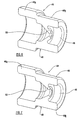
- a first embodiment of flow control device 44 is illustrated in Figures 4 to 7 , and comprises a tubular body 46 which encloses a generally cylindrical passage 48, and which has a first part 46a and a second part 46b.
- the first part 46a is adapted to fit around an outlet portion of the solenoid valve 37 and provide a substantially fluid tight seal between the solenoid valve 37 and the flow control device 44 and the second part 46b is provided with a flow restrictor part 50 which extends radially inwardly of the body 46 to partially block the passage 48.
- the flow restrictor part thus reduces the minimum cross-sectional area of the aperture, and hence the area available for flow of fluid through the outlet and out of the control chamber 17.
- the flow control device 44 is made from a resilient material such as rubber, and the flow restrictor part 50 is integral with the body 46.
- the flow restrictor part 50 is inclined relative to the body 46 such that a free edge of the flow restrictor part 50 is further from the control chamber 17 than the remainder of the flow restrictor part 50.
- the flow restrictor part 50 is sufficiently flexible, that when the pressure in the control chamber 17 increases towards the upper end of its range, the flow restrictor part 50 deforms under the pressure of the fluid in the control chamber 17 such that the free edge of the flow restrictor part is pushed towards the body 46, thus increasing the minimum cross-sectional area available for flow of fluid through the outlet. This is illustrated in Figure 7 . At low control chamber pressures, the flow restrictor part is undeformed, and thus the minimum cross-sectional area of the outlet is minimised. This is illustrated in Figure 6 .
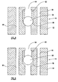
- FIG. 8 A second embodiment of flow control device is illustrated in Figures 8 and 9 .
- the flow control device comprises a body 52 which is provided with a generally central bore 54, and two by-pass bores 56, the three bores 54, 56 extending through the body 52 generally parallel to one another.
- the three bores 54, 56 provide a conduit or outlet for flow of fluid from the solenoid valve 37 to the volume of relatively low pressure fluid.
- the central bore 54 is provided with a seat 58 and a valve member 60, which in this example is generally spherical.
- the valve member 60 is urged into engagement with the seat 58 by means of a resilient biasing element 62, in this example a coil spring, such that the valve member 60 substantially closes the bore 54.
- the spring 62 is arranged such that it urges the valve member 60 towards the control chamber 17, and the strength of the spring 62 is chosen such that, if the pressure in the control chamber is at the upper end of the desired range, the force exerted on the valve member 60 by the fluid in the control chamber 17 is sufficient to overcome the biasing force of the spring 62, and push the valve member 60 away from the seat 58.
- fluid may flow through the by-pass bores 56 and the central bore 54, and therefore the minimum cross-sectional area available for- flow of fluid through the outlet is increased. This is illustrated in Figure 9 .
- the switch valve 37 may comprise a piezoelectric valve, movement of the valve member 41 effected by a piezoelectric element.
- valve assembly may be applied to any desired fluid, whether hydraulic or pneumatic.
- valve assembly is described as being used as an ABS or EBS valve, it may be used in any fluid system where is it desired to control fluid pressure in a working volume in three control states - a first where flow of fluid from a first port to a second port is permitted, a second where flow of fluid from the second port to a third port is permitted, and a third where flow of fluid between the first, second and third ports is prevented.
- the invention may be used in any system where an intermediate pressure is required to be produced by a device which switches alternatively between a higher pressure and a lower pressure source.
Landscapes
- Engineering & Computer Science (AREA)
- General Engineering & Computer Science (AREA)
- Mechanical Engineering (AREA)
- Physics & Mathematics (AREA)
- Fluid Mechanics (AREA)
- Transportation (AREA)
- Magnetically Actuated Valves (AREA)
- Regulating Braking Force (AREA)
- Lift Valve (AREA)
- Valve Housings (AREA)
- Multiple-Way Valves (AREA)
- Fluid-Driven Valves (AREA)
- Switches Operated By Changes In Physical Conditions (AREA)
- Compressor (AREA)
- Feeding And Controlling Fuel (AREA)
Claims (14)
- Ventilanordnung (10) mit einer Kammer (17), wobei die Kammer (17) einen Einlass, der angepasst ist, um mit einer Quelle eines Fluids relativ hohen Drucks verbunden zu werden, und einen Auslass, der angepasst ist, um mit einem Volumen eines Fluids relativ niedrigen Drucks verbunden zu werden, aufweist, und mit einem Schaltventil (37), welches zwischen einer ersten Stellung, in der das Ventil (37) den Auslass verschließt und den Einlass öffnet, und einer zweiten Stellung, in der das Ventil (37) den Einlass verschließt und den Auslass öffnet, schaltbar ist, dadurch gekennzeichnet, dass eine Flussregelvorrichtung (44) zwischen dem Auslass und dem Volumen des Fluid relativ niedrigen Drucks vorgesehen ist, wobei die Flussregelvorrichtung (44) ein Drosselelement aufweist, welches den Fluss des Fluids durch die Flussregelvorrichtung (44) drosselt, wobei das Ausmaß, auf welches der Fluss des Fluids begrenzt wird, absinkt, wenn der Druck des Fluids in der Kammer (17) steigt.
- Ventilanordnung (10) nach Anspruch 1, dadurch gekennzeichnet, dass das Drosselelement die Querschnittsfläche, welche für einen Fluss des Fluids durch die Flussregelvorrichtung (44) zur Verfügung steht, vergrößert, wenn der Druck des Fluids in der Kammer (17) steigt.
- Ventilanordnung (10) nach Anspruch 1 oder 2, dadurch gekennzeichnet, dass die Ventilanordnung (10) weiterhin ein Regelmittel aufweist, welches wiederholbar bedienbar ist, um das Schaltventil (37) zwischen seiner ersten und zweiten Stellung zu bewegen, um den Druck des Fluids in der Kammer (17) bei einem Wert zwischen dem Druck des Fluids relativ hohen Drucks und dem Druck des Fluids relativ niedrigen Drucks aufrechtzuerhalten.
- Ventilanordnung (10) nach Anspruch 1, 2 oder 3, dadurch gekennzeichnet, dass das Schaltventil (37) ein Ventilelement (42) aufweist, welches zwischen einer ersten Stellung, in der das Ventilelement (42) den Auslass verschließt und den Einlass öffnet, und einer zweiten Stellung, in der das Ventilelement (42) den Einlass verschließt und den Auslass öffnet, bewegbar ist.
- Ventilanordnung (10) nach einem der voranstehenden Ansprüche, dadurch gekennzeichnet, dass die Flussregelvorrichtung (44) eine Öffnung (48) aufweist, durch die Fluid von der Kammer (17) fließen kann, wobei die Ordnung (48) teilweise durch ein bewegliches Flussdrosselelement (50) blockiert ist, wobei das Flussdrosselelement (50) angepasst ist, um sich in Abhängigkeit von Kräften zu bewegen, die auf das Flussdrosselelement (50) wirken und aus der Druckdifferenz zwischen dem Fluid in der Kammer (17) und dem Fluid in dem Volumen des Fluids relativ niedrigen Drucks resultieren.
- Ventilanordnung (10) nach Anspruch 5, dadurch gekennzeichnet, dass sich das Flussdrosselelement (50) bewegt, um einen kleineren Teil der Öffnung (48) zu blockieren, wenn der Druck des Fluids in der Kammer (17) relativ zu dem Druck des Fluids in dem Volumen des Fluids relativ niedrigen Drucks ansteigt.
- Ventilanordnung (10) nach Anspruch 5 oder 6, dadurch gekennzeichnet, dass das Flussdrosselelement (50) ein Gebilde ist, welches sich von der Öffnung (48) nach innen erstreckt und aus einem nachgiebigen Material besteht.
- Ventilanordnung (10) nach einem der Ansprüche 1 bis 4, dadurch gekennzeichnet, dass die Flussregelvorrichtung (44) eine erste Öffnung (54) und eine zweite Öffnung (56) aufweist, durch die Fluid aus der Kammer (17) fließen kann, wobei die erste Öffnung (54) mit einem Ventilelement (60), einem Ventilsitz (58) und einem nachgiebigen Beaufschlagungsmittel (62) versehen ist, welches eine Vorspannkraft bereitstellt, die das Ventilelement (60) in Eingriff mit dem Ventilsitz (58) bringt, wodurch die erste Öffnung (54) blockiert wird, wobei das nachgiebige Beaufschlagungsmittel (62) so angeordnet ist, dass das Ventilelement (60) von dem Ventilsitz (58) gegen die Vorspannkraft des nachgiebigen Beaufschlagungsmittels (62) bewegt werden kann, wenn der Druck des Fluids in der Kammer (17) den Druck des Fluids an dem Auslass um einen bestimmten Betrag überschreitet.
- Ventilanordnung (10) nach Anspruch 8, dadurch gekennzeichnet, dass das Ventilelement (60) ein Kugellager ist.
- Ventilanordnung (10) nach einem der voranstehenden Ansprüche, dadurch gekennzeichnet, dass die Ventilanordnung (10) weiterhin ein Hauptventil zum Regeln des Drucks des Fluids in einem Arbeitsvolumen in drei Regelzuständen aufweist, wobei das Hauptventil drei Anschlüsse für Fluid aufweist, wobei ein erster Anschluss (11) Fluid relativ hohen Drucks dem Einlass der Kammer bereitstellt, wobei ein Fluss des Fluids von dem ersten Anschluss (11) zu einem zweiten Anschluss (13) in dem ersten Regelzustand gestattet ist, wobei ein Fluss des Fluids von dem zweiten Anschluss (13) zu einem dritten Anschluss (12) in dem zweiten Regelzustand gestattet ist, und wobei ein Fluss des Fluids zwischen dem ersten Anschluss (11), dem zweiten Anschluss (13) und dem dritten Anschluss (12) in dem dritten Regelzustand verhindert ist.
- Ventilanordnung (10) nach Anspruch 10, dadurch gekennzeichnet, dass der erste Regelzustand erreicht ist, wenn der Druck des Fluids in der Kammer (17) kleiner als ein vorbestimmter niedrigerer Druck ist, der zweite Regelzustand erreicht ist, wenn der Druck des Fluids in der Kammer (17) einen vorbestimmten höheren Wert überschreitet, und dass der dritte Regelzustand erreicht ist, wenn der Druck des Fluids in der Kammer (17) zwischen dem vorbestimmten höheren und niedrigeren Wert liegt.
- Ventilanordnung (10) nach Anspruch 10 oder 11, dadurch gekennzeichnet, dass der zweite Anschluss (13) einem Bremsbetätigungsmittel eines Fahrzeugs Fluid bereitstellt.
- Ventilanordnung (10) nach Anspruch 12, dadurch gekennzeichnet, dass die Ventilanordnung (10) ein ABS-Ventil ist.
- Ventilanordnung (10) nach Anspruch 12, dadurch gekennzeichnet, dass die Ventilanordnung (10) ein EBS-Ventil ist.
Priority Applications (1)
| Application Number | Priority Date | Filing Date | Title |
|---|---|---|---|
| PL04768037T PL1654486T3 (pl) | 2003-08-13 | 2004-08-10 | Zespół zaworowy |
Applications Claiming Priority (2)
| Application Number | Priority Date | Filing Date | Title |
|---|---|---|---|
| GB0318954A GB2404965B (en) | 2003-08-13 | 2003-08-13 | Valve assembly |
| PCT/GB2004/003461 WO2005017400A1 (en) | 2003-08-13 | 2004-08-10 | Valve assembly |
Publications (2)
| Publication Number | Publication Date |
|---|---|
| EP1654486A1 EP1654486A1 (de) | 2006-05-10 |
| EP1654486B1 true EP1654486B1 (de) | 2008-07-09 |
Family
ID=28052396
Family Applications (1)
| Application Number | Title | Priority Date | Filing Date |
|---|---|---|---|
| EP04768037A Expired - Lifetime EP1654486B1 (de) | 2003-08-13 | 2004-08-10 | Ventilanordnung |
Country Status (11)
| Country | Link |
|---|---|
| US (1) | US20060158029A1 (de) |
| EP (1) | EP1654486B1 (de) |
| CN (1) | CN100362274C (de) |
| AT (1) | ATE400759T1 (de) |
| BR (1) | BRPI0413482A (de) |
| DE (1) | DE602004014938D1 (de) |
| GB (1) | GB2404965B (de) |
| MY (1) | MY140360A (de) |
| PL (1) | PL1654486T3 (de) |
| WO (1) | WO2005017400A1 (de) |
| ZA (1) | ZA200601174B (de) |
Families Citing this family (3)
| Publication number | Priority date | Publication date | Assignee | Title |
|---|---|---|---|---|
| US9052033B2 (en) | 2008-12-22 | 2015-06-09 | Artemis Intelligent Power Limited | Valve assembly |
| GB2467957A (en) * | 2009-02-21 | 2010-08-25 | Haldex Brake Products Ltd | Brake modulator valve with acceptable cracking pressure |
| US8847103B2 (en) | 2010-07-16 | 2014-09-30 | Hypertherm, Inc. | Electronic pressure regulator |
Family Cites Families (15)
| Publication number | Priority date | Publication date | Assignee | Title |
|---|---|---|---|---|
| US1113282A (en) * | 1912-11-04 | 1914-10-13 | Charles E Golden | Emergency check-valve. |
| US2593315A (en) * | 1946-10-31 | 1952-04-15 | Dole Valve Co | Flow control device |
| US2937658A (en) * | 1956-02-13 | 1960-05-24 | Sprague Meter Company | Venting means for regulators |
| GB941816A (en) * | 1960-09-29 | 1963-11-13 | Howard Emil Thompson Jr | Fluid flow control valves |
| US3288578A (en) * | 1964-05-20 | 1966-11-29 | Tespa Ag | Valved safety device |
| US3409050A (en) * | 1965-10-12 | 1968-11-05 | Harry Swartz | Flow restrictor |
| US3566902A (en) * | 1968-05-13 | 1971-03-02 | Leslie Co | Fluid flow system |
| GB2094443B (en) * | 1981-02-11 | 1984-12-19 | Black & Decker | Improvements in or relating to fluid flow control valves |
| US4662598A (en) * | 1982-12-02 | 1987-05-05 | Bermad Kibbutz Evron | Sleeve valve with integral control chamber |
| GB2140895A (en) * | 1983-05-31 | 1984-12-05 | Ford Motor Co | Fluid valve |
| DE3433704C2 (de) * | 1984-09-13 | 1993-12-23 | Heilmeier & Weinlein | Einschraub-Drosselventil-Bausatz |
| US4924901A (en) * | 1988-10-19 | 1990-05-15 | Fluid Jet International Inc. | In line valve |
| DE4338096A1 (de) * | 1993-11-08 | 1994-11-24 | Daimler Benz Ag | Vorrichtung zur Vermeidung von Überbelastungen eines Antriebstranges |
| US7147006B2 (en) * | 2001-10-10 | 2006-12-12 | Haldex Brake Products, Ltd. | Pilot operated valve |
| EP1434958A1 (de) * | 2001-10-10 | 2004-07-07 | Haldex Brake Products Limited | Vorgesteuertes ventil |
-
2003
- 2003-08-13 GB GB0318954A patent/GB2404965B/en not_active Expired - Fee Related
-
2004
- 2004-08-10 ZA ZA200601174A patent/ZA200601174B/en unknown
- 2004-08-10 PL PL04768037T patent/PL1654486T3/pl unknown
- 2004-08-10 BR BRPI0413482 patent/BRPI0413482A/pt not_active IP Right Cessation
- 2004-08-10 WO PCT/GB2004/003461 patent/WO2005017400A1/en not_active Ceased
- 2004-08-10 CN CNB2004800229439A patent/CN100362274C/zh not_active Expired - Fee Related
- 2004-08-10 AT AT04768037T patent/ATE400759T1/de not_active IP Right Cessation
- 2004-08-10 DE DE200460014938 patent/DE602004014938D1/de not_active Expired - Fee Related
- 2004-08-10 EP EP04768037A patent/EP1654486B1/de not_active Expired - Lifetime
- 2004-08-11 MY MYPI20043262A patent/MY140360A/en unknown
-
2006
- 2006-02-10 US US11/352,160 patent/US20060158029A1/en not_active Abandoned
Also Published As
| Publication number | Publication date |
|---|---|
| GB2404965A (en) | 2005-02-16 |
| CN100362274C (zh) | 2008-01-16 |
| US20060158029A1 (en) | 2006-07-20 |
| WO2005017400A1 (en) | 2005-02-24 |
| PL1654486T3 (pl) | 2008-12-31 |
| MY140360A (en) | 2009-12-31 |
| GB2404965B (en) | 2007-05-09 |
| CN1836127A (zh) | 2006-09-20 |
| EP1654486A1 (de) | 2006-05-10 |
| ZA200601174B (en) | 2007-04-25 |
| BRPI0413482A (pt) | 2006-10-17 |
| ATE400759T1 (de) | 2008-07-15 |
| GB2404965A9 (en) | 2005-08-15 |
| GB0318954D0 (en) | 2003-09-17 |
| DE602004014938D1 (de) | 2008-08-21 |
Similar Documents
| Publication | Publication Date | Title |
|---|---|---|
| US5934766A (en) | Magnetically operated, multi-position, pressure control valve having integral metering orifice | |
| CN102325677B (zh) | 阀门组件 | |
| US7389795B2 (en) | Valve assembly | |
| US5647644A (en) | Solenoid valve, especially for hydraulic brake systems with slip control | |
| US5123718A (en) | Valve for automatic brake system | |
| US8322797B2 (en) | Hydraulic device for actuating the braking of work vehicles and the like | |
| US10967843B2 (en) | Control valve, electronically controllable brake system and method for controlling the electronically controllable brake system | |
| US5234265A (en) | Valve for automatic brake system | |
| US7147006B2 (en) | Pilot operated valve | |
| US6588856B2 (en) | Modulator relay valve assembly and method | |
| JP5070750B2 (ja) | 車両用制動装置及びそのリザーバ | |
| JP4900320B2 (ja) | マスタシリンダ | |
| JP2007210372A (ja) | ブレーキ制御装置 | |
| US20060158029A1 (en) | Valve assembly | |
| JPS599381B2 (ja) | 中継弁作動スキツド制御装置 | |
| US4449759A (en) | Service brake accelerator for rail vehicle air brake systems | |
| GB2407131A (en) | A modulator | |
| US20040168731A1 (en) | Hydraulic control valve | |
| EP3401177B1 (de) | Anordnung zur steuerung eines anhängerbremsventils, zur kopplung mit einem bremssystem eines anhängerfahrzeugs. | |
| JPH0664430A (ja) | 自動車用のサスペンション | |
| WO2003031855A1 (en) | Pilot operated valve | |
| DE4141030A1 (de) | Ventileinrichtung zur verschleissoptimierung zwischen bremsen von nutzfahrzeugen | |
| EP4538129A1 (de) | Bistabiles relaisventil | |
| US5797662A (en) | Pressure-modifying valve and electric bypass | |
| JP5136267B2 (ja) | ブレーキ制御装置 |
Legal Events
| Date | Code | Title | Description |
|---|---|---|---|
| PUAI | Public reference made under article 153(3) epc to a published international application that has entered the european phase |
Free format text: ORIGINAL CODE: 0009012 |
|
| 17P | Request for examination filed |
Effective date: 20060124 |
|
| AK | Designated contracting states |
Kind code of ref document: A1 Designated state(s): AT BE BG CH CY CZ DE DK EE ES FI FR GB GR HU IE IT LI LU MC NL PL PT RO SE SI SK TR |
|
| DAX | Request for extension of the european patent (deleted) | ||
| 17Q | First examination report despatched |
Effective date: 20061205 |
|
| GRAP | Despatch of communication of intention to grant a patent |
Free format text: ORIGINAL CODE: EPIDOSNIGR1 |
|
| GRAS | Grant fee paid |
Free format text: ORIGINAL CODE: EPIDOSNIGR3 |
|
| RBV | Designated contracting states (corrected) |
Designated state(s): AT BE BG CH CY CZ DE DK EE ES FI FR GR HU IE IT LI LU MC NL PL PT RO SE SI SK TR |
|
| GRAA | (expected) grant |
Free format text: ORIGINAL CODE: 0009210 |
|
| AK | Designated contracting states |
Kind code of ref document: B1 Designated state(s): AT BE BG CH CY CZ DE DK EE ES FI FR GR HU IE IT LI LU MC NL PL PT RO SE SI SK TR |
|
| REG | Reference to a national code |
Ref country code: CH Ref legal event code: EP |
|
| REF | Corresponds to: |
Ref document number: 602004014938 Country of ref document: DE Date of ref document: 20080821 Kind code of ref document: P |
|
| REG | Reference to a national code |
Ref country code: IE Ref legal event code: FG4D |
|
| PGFP | Annual fee paid to national office [announced via postgrant information from national office to epo] |
Ref country code: DE Payment date: 20080821 Year of fee payment: 5 |
|
| PGFP | Annual fee paid to national office [announced via postgrant information from national office to epo] |
Ref country code: FR Payment date: 20080818 Year of fee payment: 5 |
|
| REG | Reference to a national code |
Ref country code: PL Ref legal event code: T3 |
|
| NLV1 | Nl: lapsed or annulled due to failure to fulfill the requirements of art. 29p and 29m of the patents act | ||
| PG25 | Lapsed in a contracting state [announced via postgrant information from national office to epo] |
Ref country code: ES Free format text: LAPSE BECAUSE OF FAILURE TO SUBMIT A TRANSLATION OF THE DESCRIPTION OR TO PAY THE FEE WITHIN THE PRESCRIBED TIME-LIMIT Effective date: 20081020 Ref country code: NL Free format text: LAPSE BECAUSE OF FAILURE TO SUBMIT A TRANSLATION OF THE DESCRIPTION OR TO PAY THE FEE WITHIN THE PRESCRIBED TIME-LIMIT Effective date: 20080709 Ref country code: PT Free format text: LAPSE BECAUSE OF FAILURE TO SUBMIT A TRANSLATION OF THE DESCRIPTION OR TO PAY THE FEE WITHIN THE PRESCRIBED TIME-LIMIT Effective date: 20081209 |
|
| PG25 | Lapsed in a contracting state [announced via postgrant information from national office to epo] |
Ref country code: BG Free format text: LAPSE BECAUSE OF FAILURE TO SUBMIT A TRANSLATION OF THE DESCRIPTION OR TO PAY THE FEE WITHIN THE PRESCRIBED TIME-LIMIT Effective date: 20081009 Ref country code: FI Free format text: LAPSE BECAUSE OF FAILURE TO SUBMIT A TRANSLATION OF THE DESCRIPTION OR TO PAY THE FEE WITHIN THE PRESCRIBED TIME-LIMIT Effective date: 20080709 Ref country code: SI Free format text: LAPSE BECAUSE OF FAILURE TO SUBMIT A TRANSLATION OF THE DESCRIPTION OR TO PAY THE FEE WITHIN THE PRESCRIBED TIME-LIMIT Effective date: 20080709 Ref country code: AT Free format text: LAPSE BECAUSE OF FAILURE TO SUBMIT A TRANSLATION OF THE DESCRIPTION OR TO PAY THE FEE WITHIN THE PRESCRIBED TIME-LIMIT Effective date: 20080709 |
|
| PGFP | Annual fee paid to national office [announced via postgrant information from national office to epo] |
Ref country code: PL Payment date: 20081029 Year of fee payment: 5 |
|
| PG25 | Lapsed in a contracting state [announced via postgrant information from national office to epo] |
Ref country code: MC Free format text: LAPSE BECAUSE OF NON-PAYMENT OF DUE FEES Effective date: 20080831 Ref country code: BE Free format text: LAPSE BECAUSE OF FAILURE TO SUBMIT A TRANSLATION OF THE DESCRIPTION OR TO PAY THE FEE WITHIN THE PRESCRIBED TIME-LIMIT Effective date: 20080709 |
|
| PGFP | Annual fee paid to national office [announced via postgrant information from national office to epo] |
Ref country code: IT Payment date: 20081029 Year of fee payment: 5 |
|
| REG | Reference to a national code |
Ref country code: CH Ref legal event code: PL |
|
| PG25 | Lapsed in a contracting state [announced via postgrant information from national office to epo] |
Ref country code: EE Free format text: LAPSE BECAUSE OF FAILURE TO SUBMIT A TRANSLATION OF THE DESCRIPTION OR TO PAY THE FEE WITHIN THE PRESCRIBED TIME-LIMIT Effective date: 20080709 Ref country code: DK Free format text: LAPSE BECAUSE OF FAILURE TO SUBMIT A TRANSLATION OF THE DESCRIPTION OR TO PAY THE FEE WITHIN THE PRESCRIBED TIME-LIMIT Effective date: 20080709 |
|
| PLBE | No opposition filed within time limit |
Free format text: ORIGINAL CODE: 0009261 |
|
| STAA | Information on the status of an ep patent application or granted ep patent |
Free format text: STATUS: NO OPPOSITION FILED WITHIN TIME LIMIT |
|
| REG | Reference to a national code |
Ref country code: IE Ref legal event code: MM4A |
|
| PG25 | Lapsed in a contracting state [announced via postgrant information from national office to epo] |
Ref country code: CZ Free format text: LAPSE BECAUSE OF FAILURE TO SUBMIT A TRANSLATION OF THE DESCRIPTION OR TO PAY THE FEE WITHIN THE PRESCRIBED TIME-LIMIT Effective date: 20080709 Ref country code: RO Free format text: LAPSE BECAUSE OF FAILURE TO SUBMIT A TRANSLATION OF THE DESCRIPTION OR TO PAY THE FEE WITHIN THE PRESCRIBED TIME-LIMIT Effective date: 20080709 Ref country code: SK Free format text: LAPSE BECAUSE OF FAILURE TO SUBMIT A TRANSLATION OF THE DESCRIPTION OR TO PAY THE FEE WITHIN THE PRESCRIBED TIME-LIMIT Effective date: 20080709 |
|
| 26N | No opposition filed |
Effective date: 20090414 |
|
| PG25 | Lapsed in a contracting state [announced via postgrant information from national office to epo] |
Ref country code: CH Free format text: LAPSE BECAUSE OF NON-PAYMENT OF DUE FEES Effective date: 20080831 Ref country code: LI Free format text: LAPSE BECAUSE OF NON-PAYMENT OF DUE FEES Effective date: 20080831 |
|
| PG25 | Lapsed in a contracting state [announced via postgrant information from national office to epo] |
Ref country code: IE Free format text: LAPSE BECAUSE OF NON-PAYMENT OF DUE FEES Effective date: 20080810 |
|
| PG25 | Lapsed in a contracting state [announced via postgrant information from national office to epo] |
Ref country code: SE Free format text: LAPSE BECAUSE OF FAILURE TO SUBMIT A TRANSLATION OF THE DESCRIPTION OR TO PAY THE FEE WITHIN THE PRESCRIBED TIME-LIMIT Effective date: 20081009 |
|
| REG | Reference to a national code |
Ref country code: FR Ref legal event code: ST Effective date: 20100430 |
|
| PG25 | Lapsed in a contracting state [announced via postgrant information from national office to epo] |
Ref country code: CY Free format text: LAPSE BECAUSE OF FAILURE TO SUBMIT A TRANSLATION OF THE DESCRIPTION OR TO PAY THE FEE WITHIN THE PRESCRIBED TIME-LIMIT Effective date: 20080709 Ref country code: DE Free format text: LAPSE BECAUSE OF NON-PAYMENT OF DUE FEES Effective date: 20100302 Ref country code: FR Free format text: LAPSE BECAUSE OF NON-PAYMENT OF DUE FEES Effective date: 20090831 Ref country code: HU Free format text: LAPSE BECAUSE OF FAILURE TO SUBMIT A TRANSLATION OF THE DESCRIPTION OR TO PAY THE FEE WITHIN THE PRESCRIBED TIME-LIMIT Effective date: 20090110 Ref country code: LU Free format text: LAPSE BECAUSE OF NON-PAYMENT OF DUE FEES Effective date: 20080810 |
|
| PG25 | Lapsed in a contracting state [announced via postgrant information from national office to epo] |
Ref country code: TR Free format text: LAPSE BECAUSE OF FAILURE TO SUBMIT A TRANSLATION OF THE DESCRIPTION OR TO PAY THE FEE WITHIN THE PRESCRIBED TIME-LIMIT Effective date: 20080709 |
|
| PG25 | Lapsed in a contracting state [announced via postgrant information from national office to epo] |
Ref country code: GR Free format text: LAPSE BECAUSE OF FAILURE TO SUBMIT A TRANSLATION OF THE DESCRIPTION OR TO PAY THE FEE WITHIN THE PRESCRIBED TIME-LIMIT Effective date: 20081010 |
|
| PG25 | Lapsed in a contracting state [announced via postgrant information from national office to epo] |
Ref country code: IT Free format text: LAPSE BECAUSE OF NON-PAYMENT OF DUE FEES Effective date: 20090810 |
|
| PG25 | Lapsed in a contracting state [announced via postgrant information from national office to epo] |
Ref country code: PL Free format text: LAPSE BECAUSE OF NON-PAYMENT OF DUE FEES Effective date: 20090810 |
|
| REG | Reference to a national code |
Ref country code: PL Ref legal event code: LAPE |