EP1654495B1 - Ensemble bouclier thermique pour un composant acheminant un gaz chaud, notamment pour une chambre de combustion de turbine à gaz - Google Patents
Ensemble bouclier thermique pour un composant acheminant un gaz chaud, notamment pour une chambre de combustion de turbine à gaz Download PDFInfo
- Publication number
- EP1654495B1 EP1654495B1 EP04763361.5A EP04763361A EP1654495B1 EP 1654495 B1 EP1654495 B1 EP 1654495B1 EP 04763361 A EP04763361 A EP 04763361A EP 1654495 B1 EP1654495 B1 EP 1654495B1
- Authority
- EP
- European Patent Office
- Prior art keywords
- heat shield
- coolant
- cooling
- combustion chamber
- hot gas
- Prior art date
- Legal status (The legal status is an assumption and is not a legal conclusion. Google has not performed a legal analysis and makes no representation as to the accuracy of the status listed.)
- Expired - Lifetime
Links
- 238000002485 combustion reaction Methods 0.000 title claims description 44
- 238000001816 cooling Methods 0.000 claims description 64
- 239000002826 coolant Substances 0.000 claims description 56
- 238000007789 sealing Methods 0.000 claims description 16
- 229910052751 metal Inorganic materials 0.000 claims description 6
- 239000002184 metal Substances 0.000 claims description 6
- 229910001092 metal group alloy Inorganic materials 0.000 claims description 6
- 238000013017 mechanical damping Methods 0.000 claims description 2
- 238000007599 discharging Methods 0.000 claims 1
- 239000012809 cooling fluid Substances 0.000 description 20
- XEEYBQQBJWHFJM-UHFFFAOYSA-N Iron Chemical compound [Fe] XEEYBQQBJWHFJM-UHFFFAOYSA-N 0.000 description 4
- PXHVJJICTQNCMI-UHFFFAOYSA-N Nickel Chemical compound [Ni] PXHVJJICTQNCMI-UHFFFAOYSA-N 0.000 description 4
- 239000003779 heat-resistant material Substances 0.000 description 4
- 238000007664 blowing Methods 0.000 description 3
- 229910010293 ceramic material Inorganic materials 0.000 description 3
- 239000003344 environmental pollutant Substances 0.000 description 3
- 231100000719 pollutant Toxicity 0.000 description 3
- VYZAMTAEIAYCRO-UHFFFAOYSA-N Chromium Chemical compound [Cr] VYZAMTAEIAYCRO-UHFFFAOYSA-N 0.000 description 2
- 230000000903 blocking effect Effects 0.000 description 2
- 238000005266 casting Methods 0.000 description 2
- 229910052804 chromium Inorganic materials 0.000 description 2
- 239000011651 chromium Substances 0.000 description 2
- 229910017052 cobalt Inorganic materials 0.000 description 2
- 239000010941 cobalt Substances 0.000 description 2
- GUTLYIVDDKVIGB-UHFFFAOYSA-N cobalt atom Chemical compound [Co] GUTLYIVDDKVIGB-UHFFFAOYSA-N 0.000 description 2
- 230000000694 effects Effects 0.000 description 2
- 238000009434 installation Methods 0.000 description 2
- 229910052742 iron Inorganic materials 0.000 description 2
- 239000000463 material Substances 0.000 description 2
- 238000000034 method Methods 0.000 description 2
- 229910052759 nickel Inorganic materials 0.000 description 2
- 235000001674 Agaricus brunnescens Nutrition 0.000 description 1
- 229910000831 Steel Inorganic materials 0.000 description 1
- 230000004888 barrier function Effects 0.000 description 1
- 230000015572 biosynthetic process Effects 0.000 description 1
- 239000000919 ceramic Substances 0.000 description 1
- 238000013016 damping Methods 0.000 description 1
- 230000007423 decrease Effects 0.000 description 1
- 230000001419 dependent effect Effects 0.000 description 1
- 230000001627 detrimental effect Effects 0.000 description 1
- 238000011161 development Methods 0.000 description 1
- 230000018109 developmental process Effects 0.000 description 1
- 238000005315 distribution function Methods 0.000 description 1
- 238000005516 engineering process Methods 0.000 description 1
- 230000002349 favourable effect Effects 0.000 description 1
- 239000012530 fluid Substances 0.000 description 1
- 239000000446 fuel Substances 0.000 description 1
- 239000007788 liquid Substances 0.000 description 1
- 238000004519 manufacturing process Methods 0.000 description 1
- 150000002739 metals Chemical class 0.000 description 1
- 230000035515 penetration Effects 0.000 description 1
- 230000000630 rising effect Effects 0.000 description 1
- 239000010959 steel Substances 0.000 description 1
- 230000000930 thermomechanical effect Effects 0.000 description 1
Images


Classifications
-
- F—MECHANICAL ENGINEERING; LIGHTING; HEATING; WEAPONS; BLASTING
- F23—COMBUSTION APPARATUS; COMBUSTION PROCESSES
- F23R—GENERATING COMBUSTION PRODUCTS OF HIGH PRESSURE OR HIGH VELOCITY, e.g. GAS-TURBINE COMBUSTION CHAMBERS
- F23R3/00—Continuous combustion chambers using liquid or gaseous fuel
- F23R3/002—Wall structures
-
- F—MECHANICAL ENGINEERING; LIGHTING; HEATING; WEAPONS; BLASTING
- F23—COMBUSTION APPARATUS; COMBUSTION PROCESSES
- F23M—CASINGS, LININGS, WALLS OR DOORS SPECIALLY ADAPTED FOR COMBUSTION CHAMBERS, e.g. FIREBRIDGES; DEVICES FOR DEFLECTING AIR, FLAMES OR COMBUSTION PRODUCTS IN COMBUSTION CHAMBERS; SAFETY ARRANGEMENTS SPECIALLY ADAPTED FOR COMBUSTION APPARATUS; DETAILS OF COMBUSTION CHAMBERS, NOT OTHERWISE PROVIDED FOR
- F23M5/00—Casings; Linings; Walls
- F23M5/02—Casings; Linings; Walls characterised by the shape of the bricks or blocks used
-
- F—MECHANICAL ENGINEERING; LIGHTING; HEATING; WEAPONS; BLASTING
- F23—COMBUSTION APPARATUS; COMBUSTION PROCESSES
- F23M—CASINGS, LININGS, WALLS OR DOORS SPECIALLY ADAPTED FOR COMBUSTION CHAMBERS, e.g. FIREBRIDGES; DEVICES FOR DEFLECTING AIR, FLAMES OR COMBUSTION PRODUCTS IN COMBUSTION CHAMBERS; SAFETY ARRANGEMENTS SPECIALLY ADAPTED FOR COMBUSTION APPARATUS; DETAILS OF COMBUSTION CHAMBERS, NOT OTHERWISE PROVIDED FOR
- F23M5/00—Casings; Linings; Walls
- F23M5/08—Cooling thereof; Tube walls
- F23M5/085—Cooling thereof; Tube walls using air or other gas as the cooling medium
-
- F—MECHANICAL ENGINEERING; LIGHTING; HEATING; WEAPONS; BLASTING
- F23—COMBUSTION APPARATUS; COMBUSTION PROCESSES
- F23R—GENERATING COMBUSTION PRODUCTS OF HIGH PRESSURE OR HIGH VELOCITY, e.g. GAS-TURBINE COMBUSTION CHAMBERS
- F23R2900/00—Special features of, or arrangements for continuous combustion chambers; Combustion processes therefor
- F23R2900/00012—Details of sealing devices
Definitions
- the invention relates to a heat shield assembly for a component carrying a hot gas, which comprises a plurality of heat shield elements arranged next to one another on a support structure while leaving a gap, wherein a heat shield element can be attached to the support structure, so that an interior is formed that is partially cooled by one Hot gas wall is limited, with an inlet channel for the flow of a coolant in the interior.
- the invention further relates to a combustion chamber with an inner combustion liner, which has such a heat shield assembly and a gas turbine with such a combustion chamber.
- the heat shield assembly serves to protect a support structure against a hot fluid, in particular for Protection of a hot gas duct wall in gas turbine plants.
- the heat shield assembly has an inner lining made of heat-resistant material, which is composed over the entire area of heat shield elements anchored to the supporting structure. These heat shield elements are arranged side by side, leaving columns for the flow of cooling fluid and heat-mobile.
- Each of these heat shield elements has a hat part and a shaft part in the manner of a mushroom.
- the hat part is a flat or spatial polygonal plate body with straight or curved boundary lines.
- the shank part connects the central region of the plate body with the support structure.
- the hat part preferably has a triangular shape, whereby an inner lining of almost any geometry can be produced by identical hat parts.
- the hat parts and possibly other parts of the heat shield elements are made of a highly heat-resistant material, in particular of a steel.
- the support structure has bores through which a cooling fluid, in particular air, can flow into an intermediate space between the hat part and support structure and from there can flow through the gaps for the flow of the cooling fluid into a space area surrounded by the heat shield elements, for example a combustion chamber of a gas turbine plant. This cooling fluid flow reduces the penetration of hot gas into the gap.
- a metallic lining for a combustion chamber is described.
- This lining consists of a plurality of cube-shaped hollow components (cells) arranged next to one another, which are welded or soldered to a common metal plate.
- the common metal plate has each cube-shaped cell associated with exactly one opening for the inflow of cooling fluid.
- the cube-shaped cells are each arranged side by side leaving a gap. They include on each side wall in the vicinity of the common metal plate, a respective opening for the outflow of cooling fluid.
- the cooling fluid thus passes into the gaps between adjacent cube-shaped cells, flows through this column and forms on a hot gas exposable, parallel to the metallic plate surface of the cells, a cooling film.
- an open cooling system is defined, in which cooling air over a wall structure through the cells in the inside of the combustion chamber into it. The cooling air is therefore lost for further cooling purposes.
- the wall in particular for gas turbine plants, described having cooling fluid channels.
- the wall is preferably arranged in gas turbine installations between a hot room and a cooling fluid space. It is assembled from individual wall elements, wherein each of the wall elements is a made of heat-resistant material plate body. Each plate body has distributed over its base, mutually parallel cooling channels communicating at one end with a cooling fluid space and at the other end with the hot room. The cooling fluid flowing into the hot space and guided through the cooling fluid channels forms a cooling fluid film on the surface of the wall element facing the hot space and / or adjacent wall elements.
- a cooling system for cooling a combustion chamber wall is shown.
- the combustion chamber wall is formed by wall elements.
- Each wall element has a hot gas wall with a hot gas-acted outside and with an inside. Perpendicular to the inside nozzles are arranged. From these nozzles, cooling fluid emerges in the form of a concentrated stream and impinges on the inside. As a result, the hot gas wall is cooled.
- the cooling fluid is collected in a collection chamber and discharged from the collection chamber.
- all these heat shield arrangements are based on the principle that compressor air is used as the cooling medium for the combustion chamber and its lining, and as sealing air.
- the Cooling and sealing air enters the combustion chamber without having participated in the combustion. This cold air mixes with the hot gas. This reduces the temperature at the combustion chamber outlet. Therefore, the performance of the gas turbine and the efficiency of the thermodynamic process decreases.
- the compensation can be partly done by setting a higher flame temperature. However, this results in material problems and higher emission levels must be accepted.
- Another disadvantage of the stated arrangements is that arise by the entry of a significant cooling fluid mass flow into the combustion chamber at the burner air supplied pressure losses.
- the object of the invention is to provide a heat shield arrangement that can be cooled with a coolant, so that when cooling the heat shield arrangement at most a small loss of cooling fluid occurs.
- the heat shield assembly should be usable in a combustion chamber of a gas turbine.
- the invention is based on the consideration that due to the very high flame temperatures in hot gas ducts or other hot gas spaces, for example in combustion chambers of stationary gas turbines, the hot gas leading components must be actively cooled.
- a variety of cooling technologies - also in combination - can be used.
- the most commonly used cooling concepts are convection cooling, convection cooling with turbulence-increasing measures and impingement cooling. Due to the very intensive efforts, in particular, to reduce the pollutant emissions of open-cooled systems, for example of open-cooled combustors of gas turbines, the saving of cooling air is a particularly important factor in achieving these goals - here an increased NO x reduction.
- the goal for open-cooled cooling concepts is therefore to minimize the required cooling air mass flow.
- the cooling air finally escapes through the gap of adjacent heat shield elements after the cooling task has ended, in order subsequently to reach the combustion chamber.
- the outflow of cooling air protects the system from hot gas entering the gap.
- the uncontrolled blowing out of the cooling air however, more cooling air is used to lock the column, as required for the cooling task. This overdose results in excessive cooling air consumption with detrimental consequences for the overall system efficiency and pollutant emissions of the hot gas generating combustion system.
- the heat shield arrangement is special easy to implement and compared to the closed cooling concepts with coolant return constructively associated with significantly lower manufacturing costs. Due to the controlled coolant outlet into the gap can be compared to the conventional concepts coolant, for. As cooling air, can be saved and at the same time a significant reduction in pollutant emissions are effected, in particular the NO x emission. This is achieved in that a coolant outlet channel is provided for the controlled exit of coolant from the interior, which opens from the interior into the gap.
- a particularly high cooling efficiency and blocking effect of the coolant against a hot gas attack in the gap on the support structure is thereby achieved in the gap by the targeted and metered admission of the gap with coolant.
- the controlled exit of coolant from the interior can be made in a simple manner by appropriate dimensioning of the coolant outlet channel, for example with regard to the channel cross-section and the channel length.
- the heat shield element on a side wall which is inclined relative to the hot gas wall in the direction of the support structure.
- the heat shield element is formed in its basic geometry as a single-shell hollow body, which is attachable to the support structure, wherein the interior space is formed.
- the interior is bounded or fixed in exactly one direction by the support structure and in the other spatial directions by the heat shield element itself.
- the coolant outlet passage penetrates the side wall.
- the coolant outlet channel can be designed simply as a bore through the side wall, wherein the interior is connected to the gap formed by the gap.
- coolant may be due the pressure difference between the interior and the gap defined by the gap in a controlled manner from the interior through the coolant outlet channel emerge.
- a sealing element is mounted between the side wall and the support structure. Due to the inclination of the side wall in the direction of the support structure, a gap can be provided for releasable attachment of the heat shield element to the support structure for thermo-mechanical reasons, which can lead to undesirable coolant leaks. Therefore, it is particularly advantageous to seal any gaps, which can lead to an uncontrolled blowing out of coolant from the interior, by suitable sealing measures. As a result, a tight connection between the heat shield element and the support structure is provided.
- the sealing element between the side wall and the support structure is a particularly simple but effective measure to further reduce the coolant consumption.
- the sealing element can additionally assume a damping function, so that the heat shield elements of the heat shield arrangement are mechanically damped on the support structure.
- the interior of a heat shield element is assigned an impact cooling device, so that the hot gas wall can be cooled by means of impingement cooling.
- the impingement cooling is a particularly effective method of cooling the heat shield assembly, the coolant impinges on the hot gas wall in a plurality of discrete coolant jets perpendicular to the hot gas wall and efficiently cools the hot gas wall in accordance with the interior.
- the impact cooling device is formed by a plurality of inlet channels for coolant, which are introduced into the support structure.
- a corresponding multiplicity of inlet ducts which enter into an interior of a Open heat shield element, an impact cooling device is already realized in a simple manner.
- the support structure in addition to the function of supporting the heat shield assembly, has at the same time a coolant distribution function through the plurality of inlet channels for the coolant introduced into the support structure.
- the inlet channels can be designed as holes in the wall of the support structure.
- the heat shield element consists of a metal or a metal alloy.
- high-temperature-resistant metallic alloys based on iron, chromium, nickel or cobalt are suitable for this purpose. Since metals or metal alloys are well suited for a casting process, the heat shield element is advantageously designed as a casting.
- the heat shield assembly is in a particularly preferred embodiment suitable for use in a combustion chamber lining a combustion chamber.
- a combustion chamber provided with a heat shield arrangement is preferably suitable as a combustion chamber of a gas turbine, in particular of a stationary gas turbine.
- the gas turbine 1 has a compressor 2 for the combustion air, a combustion chamber 4 and a turbine 6 for driving a compressor 2 and a generator, not shown, or a working machine.
- the turbine 6 and the compressor 2 are arranged on a common, also called turbine rotor turbine shaft 8, with which the generator or the working machine is connected, and which is rotatably mounted about its central axis 9.
- the running in the manner of an annular combustion chamber 4 is equipped with a number of burners 10 for the combustion of a liquid or gaseous fuel.
- the turbine 6 has a number of rotatable blades 12 connected to the turbine shaft 8.
- the blades 12 are arranged in a ring on the turbine shaft 8 and thus form a number of blade rows.
- the turbine 6 comprises a number of fixed vanes 14, which are also fixed in a ring shape with the formation of rows of vanes on an inner casing 16 of the turbine 6.
- the blades 12 serve to drive the turbine shaft by momentum transfer from the hot medium flowing through the turbine 6, the working medium or the hot gas M.
- the vanes 14 serve to guide the flow of the working medium M between two successive blade rows or blade rows seen in the flow direction of the working medium M.
- a successive pair of a ring of vanes 14 or a vane 3 and a ring of blades 12 or a blade row is also referred to as a turbine stage.
- Each vane 14 has a platform 18, also referred to as a blade root, which is arranged to fix the respective vane 14 on the inner housing 16 of the turbine 6 as a wall element.
- the platform 18 is a thermally comparatively heavily loaded component, which forms the outer boundary of a hot gas channel for the working medium M flowing through the turbine 6.
- Each blade 12 is attached to the turbine shaft 8 in an analogous manner via a platform 20, also referred to as a blade root.
- each guide ring 21 on the inner housing 16 of the turbine 6 is arranged between the spaced-apart platforms 18 of the guide vanes 14 of two adjacent rows of guide vanes.
- the outer surface of each guide ring 21 is also exposed to the hot, the turbine 6 flowing through the working medium M and spaced in the radial direction from the outer end 22 of the blade 12 opposite it through a gap.
- the guide rings 21 arranged between adjacent guide blade rows serve, in particular, as cover elements which protect the inner wall 16 or other housing installation parts from thermal overload by the hot working medium M, the hot gas, flowing through the turbine 6.
- the combustion chamber 4 is delimited by a combustion chamber housing 29, wherein a combustion chamber wall 24 is formed on the combustion chamber side.
- the combustion chamber 4 is designed as a so-called annular combustion chamber, in whose plurality of burners 10 arranged around the turbine shaft 8 in the circumferential direction open into a common combustion chamber space.
- the combustion chamber 4 is configured in its entirety as an annular structure which is positioned around the turbine shaft 8 around.
- the combustion chamber is designed for a comparatively high temperature of the working medium M of about 1200 ° C to 1500 ° C.
- the combustion chamber wall 24 is provided on its side facing the working medium M side with a heat shield assembly 26 which forms a combustion chamber lining. Due to the high temperatures inside the combustion chamber 4, a cooling system is also provided for the heat shield assembly 26.
- the cooling system is based on the principle of impingement cooling, in which the cooling air is blown as coolant K under sufficiently high pressure at a plurality of points to the cooling component perpendicular to its component surface under pressure.
- the cooling system can also be based on the principle of convective cooling or make use of this cooling principle in addition to the impingement cooling.
- the cooling system is designed with a simple structure for a reliable, comprehensive coverage of the heat shield assembly with coolant K and also to a very low coolant consumption.
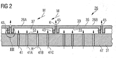
- FIG. 2 a heat shield assembly 26, as it is particularly suitable for use as a heat-resistant lining of a combustion chamber 4 of a gas turbine 1.
- the heat shield arrangement 26 comprises heat shield elements 26A, 26B, which are arranged next to one another on a support structure 31, leaving a gap 45.
- the heat shield elements 26A, 26B have a hot gas wall 39 to be cooled, which has a hot side 35 facing the hot gas M and acted upon by the hot gas M during operation, and a cold side 33 opposite the hot side 35.
- the heat shield elements 26A, 26B are produced from their cold side 33 by a coolant K, for example cooling air, cooled, which is delivered to the interior 37 formed between the heat shield elements 26A, 26B and the support structure 31 by suitable inlet channels 41, 41A, 41B, 41C and in a direction perpendicular to the cold side 33 of a respective heat shield element 26A, 26B is passed.
- a coolant K for example cooling air
- the principle of open cooling is used.
- the at least partially heated air is added to the hot gas M.
- a coolant outlet channel 43 is provided, which opens from the interior 37 into the gap 45.
- the gap 45 is a precisely predetermined mass flow of coolant K deliverable.
- the plurality of inlet channels 41, 41A, 41B, 41C which are each assigned to an interior space 37 of a respective heat shield element 26A, 26B, form an impingement cooling device 53, so that the hot gas wall 39 can be cooled particularly effectively by means of impingement cooling.
- the inlet channels 41, 41A, 41B, 41C for the coolant K are here introduced through corresponding holes in the wall 47 of the support structure.
- the inlet channels 41, 41A, 41B, 41C open into the interior 37 in such a way that a vertical admission of the hot gas wall 39 is achieved.
- the coolant K flows from the interior space 37 in a controlled manner through the correspondingly dimensioned coolant outlet channel 43 into the gap 45, where a barrier effect against the hot gas M is achieved, which protects the critical components, such as the support structure 31 ,
- FIG. 3 shows in an enlarged view the detail III in FIG. 2 shown heat shield assembly.
- the heat shield element 26A has a side wall 49, which is inclined towards the hot gas wall 39 in the direction of the support structure 31.
- the heat shield element 26B arranged adjacent to the heat shield element 26A is configured in the same way with a side wall 49.
- the coolant outlet channel 43 is formed as a bore through the side wall 43 of the heat shield element 26A, which opens the side wall 43 into the gap 45 under an oblique angle rising slightly in the direction of the hot side 35.
- the coolant K leaves the gap 45 as far as possible after forming a blocking effect in the gap 45, forming a cooling film of coolant K along the hot side 35 of the heat shield element 26B adjacent to the heat shield element 26A.
- the side walls 49 are not directly on the support structure 31, but are connected via a respective sealing element 51 with the support structure 31.
- the sealing elements 51 fulfill both a sealing function for the coolant K and a mechanical damping function for the heat shield assembly 26.
- the sealing element 51 prevents coolant K in an uncontrolled manner from the interior 37 into the gap 45 and blown out in the direction of the hot side 35 can be. Rather, the sealing element 51 causes an additional reduction in the need for coolant K for cooling de heat shield assembly 26.
- a particularly favorable coolant balance is achieved.
- a longitudinal underflow along the wall 47 of the support structure 31 facing the interior 37 is achieved by the respective sealing elements 51 assigned to the interior 37.
- the tight connection between the heat shield element 26A, 26B and the support structure 31 via the sealing elements 51 is a particularly simple and effective measure to further reduce the coolant consumption.
- the coolant outlet channel 43 extends through the wall 47 of the support structure 31.
- a targeted delivery of the coolant K in the gap 45 after performing the cooling task to a heat shield element 26A is possible.
- the gap 45 and the gap 45 in the vicinity of the mouth of the coolant outlet channel 43 bounding sealing elements 51 are thereby cooled.
- the gap 45 limiting side walls 49 are additionally cooled convectively.
Landscapes
- Engineering & Computer Science (AREA)
- Chemical & Material Sciences (AREA)
- Combustion & Propulsion (AREA)
- Mechanical Engineering (AREA)
- General Engineering & Computer Science (AREA)
- Turbine Rotor Nozzle Sealing (AREA)
Claims (6)
- Agencement ( 26 ) de bouclier thermique pour un composant conduisant un gaz ( M ) chaud, qui comprend une pluralité d'éléments ( 26A, 26B ) de bouclier thermique disposés sur une structure ( 31 ) porteuse, les uns à côté des autres, en laissant un intervalle ( 45 ), un élément ( 26A, 26B ) de bouclier thermique pouvant être mis sur la structure ( 31 ) porteuse, de manière à former un espace ( 37 ) intérieur, délimité par endroit par une paroi ( 39 ) pour du gaz chaud à refroidir, comprenant un conduit ( 41 ) d'entrée pour l'entrée d'un fluide ( K ) de refroidissement dans l'espace ( 37 ) intérieur, dans lequel l'élément ( 26A, 26B ) de bouclier thermique a une paroi ( 49 ) latérale, qui est inclinée, par rapport à la paroi ( 39 ) pour du gaz chaud, dans la direction de la structure ( 31 ) porteuse et il est prévu, pour la sortie contrôlée du fluide ( K ) de refroidissement de l'espace ( 37 ) intérieur, un conduit ( 43 ) de sortie du fluide de refroidissement, qui débouche de l'espace ( 37 ) intérieur dans l'intervalle ( 45 ), caractérisé en ce que le conduit ( 43 ) de sortie du fluide de refroidissement traverse la paroi ( 49 ) latérale et en ce qu'un élément ( 51 ) d'étanchéité, ayant une fonction d'amortissement mécanique, est mis entre la paroi ( 49 ) latérale et la structure ( 31 ) porteuse.
- Agencement ( 26 ) de bouclier thermique suivant la revendication 1,
caractérisé en ce qu'un dispositif ( 53 ) de refroidissement par rebondissement est associé à l'espace ( 37 ) intérieur d'un élément ( 26A, 26B ) de bouclier thermique, de manière à pouvoir refroidir la paroi ( 39 ) pour du gaz chaud au moyen d'un refroidissement par rebondissement. - Agencement ( 26 ) de bouclier thermique suivant la revendication 2,
caractérisé en ce que le dispositif ( 53 ) de refroidissement par rebondissement est formé d'une pluralité de conduits ( 41, 41A, 41B, 41C ) d'entrée de fluide ( K ) de refroidissement, qui sont ménagés dans la structure ( 31 ) porteuse. - Agencement ( 26 ) de bouclier thermique suivant l'une des revendications précédentes,
caractérisé en ce que l'élément ( 26A, 26B ) de bouclier thermique est en un métal ou en un alliage métallique. - Chambre de combustion ( 4 ) comprenant un agencement ( 26 ) de bouclier thermique suivant l'une des revendications précédentes.
- Turbine ( 1 ) à gaz ayant une chambre de combustion ( 4 ) suivant la revendication 5.
Priority Applications (1)
| Application Number | Priority Date | Filing Date | Title |
|---|---|---|---|
| EP04763361.5A EP1654495B1 (fr) | 2003-08-13 | 2004-07-20 | Ensemble bouclier thermique pour un composant acheminant un gaz chaud, notamment pour une chambre de combustion de turbine à gaz |
Applications Claiming Priority (3)
| Application Number | Priority Date | Filing Date | Title |
|---|---|---|---|
| EP03018415A EP1507116A1 (fr) | 2003-08-13 | 2003-08-13 | Ensemble bouclier thermique pour un composant acheminant un gaz chaud, notamment pour une chambre de combustion de turbine à gaz |
| PCT/EP2004/008116 WO2005019730A1 (fr) | 2003-08-13 | 2004-07-20 | Systeme de bouclier thermique pour element constitutif guidant un gaz chaud, notamment pour chambre a combustion de turbine a gaz |
| EP04763361.5A EP1654495B1 (fr) | 2003-08-13 | 2004-07-20 | Ensemble bouclier thermique pour un composant acheminant un gaz chaud, notamment pour une chambre de combustion de turbine à gaz |
Publications (2)
| Publication Number | Publication Date |
|---|---|
| EP1654495A1 EP1654495A1 (fr) | 2006-05-10 |
| EP1654495B1 true EP1654495B1 (fr) | 2017-04-12 |
Family
ID=33560795
Family Applications (2)
| Application Number | Title | Priority Date | Filing Date |
|---|---|---|---|
| EP03018415A Withdrawn EP1507116A1 (fr) | 2003-08-13 | 2003-08-13 | Ensemble bouclier thermique pour un composant acheminant un gaz chaud, notamment pour une chambre de combustion de turbine à gaz |
| EP04763361.5A Expired - Lifetime EP1654495B1 (fr) | 2003-08-13 | 2004-07-20 | Ensemble bouclier thermique pour un composant acheminant un gaz chaud, notamment pour une chambre de combustion de turbine à gaz |
Family Applications Before (1)
| Application Number | Title | Priority Date | Filing Date |
|---|---|---|---|
| EP03018415A Withdrawn EP1507116A1 (fr) | 2003-08-13 | 2003-08-13 | Ensemble bouclier thermique pour un composant acheminant un gaz chaud, notamment pour une chambre de combustion de turbine à gaz |
Country Status (5)
| Country | Link |
|---|---|
| US (1) | US7849694B2 (fr) |
| EP (2) | EP1507116A1 (fr) |
| JP (1) | JP4436837B2 (fr) |
| CN (1) | CN1829879A (fr) |
| WO (1) | WO2005019730A1 (fr) |
Families Citing this family (50)
| Publication number | Priority date | Publication date | Assignee | Title |
|---|---|---|---|---|
| EP1650503A1 (fr) * | 2004-10-25 | 2006-04-26 | Siemens Aktiengesellschaft | Méthode de refroidissement d'un bouclier thermique et bouclier thermique |
| DE102005046731A1 (de) * | 2005-04-19 | 2006-11-02 | Siemens Ag | Hitzeschildanordnung |
| WO2008017551A2 (fr) * | 2006-08-07 | 2008-02-14 | Alstom Technology Ltd | Chambre de combustion d'une installation d'incinération |
| WO2008017550A1 (fr) * | 2006-08-07 | 2008-02-14 | Alstom Technology Ltd | Chambre de combustion d'une installation de combustion |
| US8522557B2 (en) | 2006-12-21 | 2013-09-03 | Siemens Aktiengesellschaft | Cooling channel for cooling a hot gas guiding component |
| DE102008028025B4 (de) * | 2008-06-12 | 2011-05-05 | Siemens Aktiengesellschaft | Hitzeschildanordnung |
| US9587832B2 (en) * | 2008-10-01 | 2017-03-07 | United Technologies Corporation | Structures with adaptive cooling |
| RU2398160C1 (ru) * | 2009-05-25 | 2010-08-27 | Открытое акционерное общество "Климов" | Камера сгорания газотурбинного двигателя (варианты) |
| US9534783B2 (en) * | 2011-07-21 | 2017-01-03 | United Technologies Corporation | Insert adjacent to a heat shield element for a gas turbine engine combustor |
| EP2549063A1 (fr) | 2011-07-21 | 2013-01-23 | Siemens Aktiengesellschaft | Élément d'écran thermique pour une turbine à gaz |
| DE102012204103A1 (de) * | 2012-03-15 | 2013-09-19 | Siemens Aktiengesellschaft | Hitzeschildelement für einen Verdichterluftbypass um die Brennkammer |
| EP2728255A1 (fr) * | 2012-10-31 | 2014-05-07 | Alstom Technology Ltd | Agencement de segment de gaz chaud |
| US9714611B2 (en) | 2013-02-15 | 2017-07-25 | Siemens Energy, Inc. | Heat shield manifold system for a midframe case of a gas turbine engine |
| US10634351B2 (en) | 2013-04-12 | 2020-04-28 | United Technologies Corporation | Combustor panel T-junction cooling |
| US10816201B2 (en) * | 2013-09-13 | 2020-10-27 | Raytheon Technologies Corporation | Sealed combustor liner panel for a gas turbine engine |
| WO2015039074A1 (fr) | 2013-09-16 | 2015-03-19 | United Technologies Corporation | Variation contrôlée de la chute de pression par refroidissement par effusion dans une chambre de combustion à double paroi d'une turbine à gaz |
| WO2015039075A1 (fr) | 2013-09-16 | 2015-03-19 | United Technologies Corporation | Trous de refroidissement de chemise de chambre de combustion coudée formés à travers une structure transversale à l'intérieur d'une chambre de combustion de turbine à gaz |
| EP3060847B1 (fr) | 2013-10-24 | 2019-09-18 | United Technologies Corporation | Géométrie de passage pour chambre de combustion de moteur de type turbine à gaz |
| EP3071816B1 (fr) | 2013-11-21 | 2019-09-18 | United Technologies Corporation | Refroidissement d'une structure à parois multiples d'un moteur à turbine |
| EP3967854B1 (fr) * | 2013-11-25 | 2023-07-05 | Raytheon Technologies Corporation | Agencement pour un moteur à turbine |
| EP3099976B1 (fr) * | 2014-01-30 | 2019-03-13 | United Technologies Corporation | Flux de refroidissement pour un panneau principal dans une chambre de combustion de moteur à turbine à gaz |
| EP2927592A1 (fr) * | 2014-03-31 | 2015-10-07 | Siemens Aktiengesellschaft | Élément de bouclier thermique, bouclier thermique et turbomachine |
| US10041675B2 (en) | 2014-06-04 | 2018-08-07 | Pratt & Whitney Canada Corp. | Multiple ventilated rails for sealing of combustor heat shields |
| JP6282184B2 (ja) * | 2014-06-19 | 2018-02-21 | 三菱日立パワーシステムズ株式会社 | 伝熱装置及びそれを備えたガスタービン燃焼器 |
| US10012385B2 (en) * | 2014-08-08 | 2018-07-03 | Pratt & Whitney Canada Corp. | Combustor heat shield sealing |
| US9534785B2 (en) | 2014-08-26 | 2017-01-03 | Pratt & Whitney Canada Corp. | Heat shield labyrinth seal |
| DE102014221225A1 (de) * | 2014-10-20 | 2016-04-21 | Siemens Aktiengesellschaft | Hitzeschildelement und Verfahren zu seiner Herstellung |
| US9896970B2 (en) | 2014-11-14 | 2018-02-20 | General Electric Company | Method and system for sealing an annulus |
| DE102015202570A1 (de) | 2015-02-12 | 2016-08-18 | Rolls-Royce Deutschland Ltd & Co Kg | Abdichtung eines Randspalts zwischen Effusionsschindeln einer Gasturbinenbrennkammer |
| DE102015205975A1 (de) * | 2015-04-02 | 2016-10-06 | Siemens Aktiengesellschaft | Umführungs-Hitzeschildelement |
| GB201603166D0 (en) * | 2016-02-24 | 2016-04-06 | Rolls Royce Plc | A combustion chamber |
| US10619854B2 (en) | 2016-11-30 | 2020-04-14 | United Technologies Corporation | Systems and methods for combustor panel |
| US10739001B2 (en) | 2017-02-14 | 2020-08-11 | Raytheon Technologies Corporation | Combustor liner panel shell interface for a gas turbine engine combustor |
| US10823411B2 (en) | 2017-02-23 | 2020-11-03 | Raytheon Technologies Corporation | Combustor liner panel end rail cooling enhancement features for a gas turbine engine combustor |
| US10718521B2 (en) | 2017-02-23 | 2020-07-21 | Raytheon Technologies Corporation | Combustor liner panel end rail cooling interface passage for a gas turbine engine combustor |
| US10830434B2 (en) | 2017-02-23 | 2020-11-10 | Raytheon Technologies Corporation | Combustor liner panel end rail with curved interface passage for a gas turbine engine combustor |
| US10677462B2 (en) | 2017-02-23 | 2020-06-09 | Raytheon Technologies Corporation | Combustor liner panel end rail angled cooling interface passage for a gas turbine engine combustor |
| US10941937B2 (en) * | 2017-03-20 | 2021-03-09 | Raytheon Technologies Corporation | Combustor liner with gasket for gas turbine engine |
| KR101872856B1 (ko) * | 2017-04-27 | 2018-07-02 | 연세대학교 산학협력단 | 다층 복합 충돌 및 유출 냉각이 가능한 중공 핀과 충돌 흡입 구조의 가스터빈 연소기 라이너 |
| US10663168B2 (en) | 2017-08-02 | 2020-05-26 | Raytheon Technologies Corporation | End rail mate-face low pressure vortex minimization |
| US11009230B2 (en) | 2018-02-06 | 2021-05-18 | Raytheon Technologies Corporation | Undercut combustor panel rail |
| US11248791B2 (en) | 2018-02-06 | 2022-02-15 | Raytheon Technologies Corporation | Pull-plane effusion combustor panel |
| US10830435B2 (en) | 2018-02-06 | 2020-11-10 | Raytheon Technologies Corporation | Diffusing hole for rail effusion |
| US11022307B2 (en) | 2018-02-22 | 2021-06-01 | Raytheon Technology Corporation | Gas turbine combustor heat shield panel having multi-direction hole for rail effusion cooling |
| DE102018212394B4 (de) * | 2018-07-25 | 2024-03-28 | Rolls-Royce Deutschland Ltd & Co Kg | Brennkammerbaugruppe mit Strömungsleiteinrichtung aufweisendem Wandelement |
| US11073285B2 (en) * | 2019-06-21 | 2021-07-27 | Raytheon Technologies Corporation | Combustor panel configuration with skewed side walls |
| EP3964753A1 (fr) * | 2020-09-07 | 2022-03-09 | Siemens Energy Global GmbH & Co. KG | Joint d'étanchéité destiné à l'utilisation dans un élément pare-chaleur |
| CN112923398B (zh) * | 2021-03-04 | 2022-07-22 | 西北工业大学 | 一种加力燃烧室防振隔热屏 |
| US20230323813A1 (en) * | 2022-04-08 | 2023-10-12 | General Electric Company | Heat exchanger with cooling architecture |
| CN115930259B (zh) * | 2023-01-31 | 2025-07-11 | 上海电气燃气轮机有限公司 | 一种燃气轮机燃烧室的隔热瓦及热屏 |
Family Cites Families (20)
| Publication number | Priority date | Publication date | Assignee | Title |
|---|---|---|---|---|
| GB849255A (en) | 1956-11-01 | 1960-09-21 | Josef Cermak | Method of and arrangements for cooling the walls of combustion spaces and other spaces subject to high thermal stresses |
| EP0224817B1 (fr) | 1985-12-02 | 1989-07-12 | Siemens Aktiengesellschaft | Ecran de protection contre la chaleur pour éléments structuraux d'une turbine à gaz |
| US4838030A (en) * | 1987-08-06 | 1989-06-13 | Avco Corporation | Combustion chamber liner having failure activated cooling and dectection system |
| RU2076275C1 (ru) * | 1990-07-17 | 1997-03-27 | Сименс АГ | Отрезок трубы, в частности жаровая труба с внутренним объемом для направления горячего газа и теплозащитным экраном |
| US5431020A (en) * | 1990-11-29 | 1995-07-11 | Siemens Aktiengesellschaft | Ceramic heat shield on a load-bearing structure |
| US5435139A (en) * | 1991-03-22 | 1995-07-25 | Rolls-Royce Plc | Removable combustor liner for gas turbine engine combustor |
| US5216886A (en) | 1991-08-14 | 1993-06-08 | The United States Of America As Represented By The Secretary Of The Air Force | Segmented cell wall liner for a combustion chamber |
| US5363654A (en) * | 1993-05-10 | 1994-11-15 | General Electric Company | Recuperative impingement cooling of jet engine components |
| GB2298266A (en) * | 1995-02-23 | 1996-08-28 | Rolls Royce Plc | A cooling arrangement for heat resistant tiles in a gas turbine engine combustor |
| FR2752916B1 (fr) * | 1996-09-05 | 1998-10-02 | Snecma | Chemise de protection thermique pour chambre de combustion de turboreacteur |
| DE59706065D1 (de) | 1996-09-26 | 2002-02-21 | Siemens Ag | Hitzeschildkomponente mit kühlfluidrückführung und hitzeschildanordnung für eine heissgasführende komponente |
| DE29714742U1 (de) | 1997-08-18 | 1998-12-17 | Siemens AG, 80333 München | Hitzeschildkomponente mit Kühlfluidrückführung und Hitzeschildanordnung für eine heißgasführende Komponente |
| WO1999047874A1 (fr) * | 1998-03-19 | 1999-09-23 | Siemens Aktiengesellschaft | Segment de paroi pour une chambre de combustion, et chambre de combustion |
| DE19963371A1 (de) * | 1999-12-28 | 2001-07-12 | Alstom Power Schweiz Ag Baden | Gekühltes Hitzeschild |
| GB2361303B (en) * | 2000-04-14 | 2004-10-20 | Rolls Royce Plc | Wall structure for a gas turbine engine combustor |
| US6606861B2 (en) * | 2001-02-26 | 2003-08-19 | United Technologies Corporation | Low emissions combustor for a gas turbine engine |
| EP1284390A1 (fr) * | 2001-06-27 | 2003-02-19 | Siemens Aktiengesellschaft | Ensemble bouclier thermique pour un composant acheminant un gaz chaud, notamment pour des pièces de structure de turbines à gaz |
| DE10214570A1 (de) * | 2002-04-02 | 2004-01-15 | Rolls-Royce Deutschland Ltd & Co Kg | Mischluftloch in Gasturbinenbrennkammer mit Brennkammerschindeln |
| EP1443275B1 (fr) * | 2003-01-29 | 2008-08-13 | Siemens Aktiengesellschaft | Chambre de combustion |
| US7219498B2 (en) * | 2004-09-10 | 2007-05-22 | Honeywell International, Inc. | Waffled impingement effusion method |
-
2003
- 2003-08-13 EP EP03018415A patent/EP1507116A1/fr not_active Withdrawn
-
2004
- 2004-07-20 JP JP2006522925A patent/JP4436837B2/ja not_active Expired - Fee Related
- 2004-07-20 EP EP04763361.5A patent/EP1654495B1/fr not_active Expired - Lifetime
- 2004-07-20 US US10/568,115 patent/US7849694B2/en not_active Expired - Fee Related
- 2004-07-20 CN CNA2004800216354A patent/CN1829879A/zh active Pending
- 2004-07-20 WO PCT/EP2004/008116 patent/WO2005019730A1/fr not_active Ceased
Non-Patent Citations (1)
| Title |
|---|
| None * |
Also Published As
| Publication number | Publication date |
|---|---|
| US20090077974A1 (en) | 2009-03-26 |
| JP4436837B2 (ja) | 2010-03-24 |
| EP1654495A1 (fr) | 2006-05-10 |
| EP1507116A1 (fr) | 2005-02-16 |
| WO2005019730A1 (fr) | 2005-03-03 |
| US7849694B2 (en) | 2010-12-14 |
| JP2007501927A (ja) | 2007-02-01 |
| CN1829879A (zh) | 2006-09-06 |
Similar Documents
| Publication | Publication Date | Title |
|---|---|---|
| EP1654495B1 (fr) | Ensemble bouclier thermique pour un composant acheminant un gaz chaud, notamment pour une chambre de combustion de turbine à gaz | |
| EP1636526B1 (fr) | Chambre a combustion | |
| EP1005620B1 (fr) | Element constitutif d'un bouclier thermique a recirculation du fluide de refroidissement | |
| EP0244693B1 (fr) | Dispositif protecteur contre le surchauffage à gaz chaud pour les propulseurs à turbine à gaz | |
| DE60202212T2 (de) | Kühlbares segment für turbomaschinen und turbinen mit brennkammer | |
| EP0928396B1 (fr) | Element a effet de bouclier thermique a recyclage du fluide de refroidissement et systeme de bouclier thermique pour element de guidage de gaz chauds | |
| DE102005025823B4 (de) | Verfahren und Vorrichtung zum Kühlen einer Brennkammerauskleidung und eines Übergangsteils einer Gasturbine | |
| DE60224339T2 (de) | Kühleinsatz mit tangentialer Ausströmung | |
| EP2084368B1 (fr) | Aube de turbine | |
| DE3200972A1 (de) | Brennereinsatz, insbesondere fuer ein gasturbinentriebwerk | |
| DE102008037385A1 (de) | Auskleidungsanordnung mit Turbulatoren am hinteren Ende und Kühlverfahren | |
| EP1659262A1 (fr) | Aube de turbine à gaz et méthode de refroidissement de ladite aube | |
| EP2184445A1 (fr) | Support d'aubes statorique axialement segmenté d'une turbine à gaz | |
| WO2014177371A1 (fr) | Lance de brûleur dotée d'un bouclier thermique, pour brûleur d'une turbine à gaz | |
| EP1409926A1 (fr) | Dispositif de refroidissement par choc | |
| WO2013135859A2 (fr) | Dérivation de chambre de combustion annulaire | |
| EP1672281A1 (fr) | Elément de protection thermique | |
| EP2347100B1 (fr) | Turbine à gaz avec insert de refroidissement | |
| EP1588102B1 (fr) | Element de bouclier thermique, chambre de combustion et turbine a gaz | |
| WO2004109187A1 (fr) | Element de protection thermique | |
| EP1256695A1 (fr) | Elément d'anneau de guidage de turbine à gaz, et turbine à gaz comportant ledit élément | |
| EP2184449A1 (fr) | Support d'aube directrice, turbine à gaz et moteur à turbine à gaz ou à vapeur avec un tel support d'aube directrice | |
| EP1460339A1 (fr) | Turbine à gaz | |
| EP1398462A1 (fr) | Turbine à gaz et pièce de transition | |
| EP1420208A1 (fr) | Chambre de combustion |
Legal Events
| Date | Code | Title | Description |
|---|---|---|---|
| PUAI | Public reference made under article 153(3) epc to a published international application that has entered the european phase |
Free format text: ORIGINAL CODE: 0009012 |
|
| 17P | Request for examination filed |
Effective date: 20060102 |
|
| AK | Designated contracting states |
Kind code of ref document: A1 Designated state(s): CH DE ES GB IT LI |
|
| DAX | Request for extension of the european patent (deleted) | ||
| RBV | Designated contracting states (corrected) |
Designated state(s): CH DE ES GB IT LI |
|
| RAP1 | Party data changed (applicant data changed or rights of an application transferred) |
Owner name: SIEMENS AKTIENGESELLSCHAFT |
|
| RAP1 | Party data changed (applicant data changed or rights of an application transferred) |
Owner name: SIEMENS AKTIENGESELLSCHAFT |
|
| GRAP | Despatch of communication of intention to grant a patent |
Free format text: ORIGINAL CODE: EPIDOSNIGR1 |
|
| INTG | Intention to grant announced |
Effective date: 20161118 |
|
| GRAS | Grant fee paid |
Free format text: ORIGINAL CODE: EPIDOSNIGR3 |
|
| GRAA | (expected) grant |
Free format text: ORIGINAL CODE: 0009210 |
|
| AK | Designated contracting states |
Kind code of ref document: B1 Designated state(s): CH DE ES GB IT LI |
|
| REG | Reference to a national code |
Ref country code: GB Ref legal event code: FG4D Free format text: NOT ENGLISH |
|
| REG | Reference to a national code |
Ref country code: DE Ref legal event code: R081 Ref document number: 502004015508 Country of ref document: DE Owner name: SIEMENS ENERGY GLOBAL GMBH & CO. KG, DE Free format text: FORMER OWNER: SIEMENS AKTIENGESELLSCHAFT, 80333 MUENCHEN, DE Ref country code: CH Ref legal event code: EP |
|
| REG | Reference to a national code |
Ref country code: DE Ref legal event code: R096 Ref document number: 502004015508 Country of ref document: DE |
|
| REG | Reference to a national code |
Ref country code: CH Ref legal event code: NV Representative=s name: SIEMENS SCHWEIZ AG, CH |
|
| RAP2 | Party data changed (patent owner data changed or rights of a patent transferred) |
Owner name: SIEMENS AKTIENGESELLSCHAFT |
|
| REG | Reference to a national code |
Ref country code: CH Ref legal event code: PCOW Free format text: NEW ADDRESS: WERNER-VON-SIEMENS-STRASSE 1, 80333 MUENCHEN (DE) |
|
| PG25 | Lapsed in a contracting state [announced via postgrant information from national office to epo] |
Ref country code: ES Free format text: LAPSE BECAUSE OF FAILURE TO SUBMIT A TRANSLATION OF THE DESCRIPTION OR TO PAY THE FEE WITHIN THE PRESCRIBED TIME-LIMIT Effective date: 20170412 |
|
| REG | Reference to a national code |
Ref country code: DE Ref legal event code: R097 Ref document number: 502004015508 Country of ref document: DE |
|
| PLBE | No opposition filed within time limit |
Free format text: ORIGINAL CODE: 0009261 |
|
| STAA | Information on the status of an ep patent application or granted ep patent |
Free format text: STATUS: NO OPPOSITION FILED WITHIN TIME LIMIT |
|
| 26N | No opposition filed |
Effective date: 20180115 |
|
| REG | Reference to a national code |
Ref country code: DE Ref legal event code: R081 Ref document number: 502004015508 Country of ref document: DE Owner name: SIEMENS ENERGY GLOBAL GMBH & CO. KG, DE Free format text: FORMER OWNER: SIEMENS AKTIENGESELLSCHAFT, 80333 MUENCHEN, DE |
|
| PGFP | Annual fee paid to national office [announced via postgrant information from national office to epo] |
Ref country code: CH Payment date: 20211022 Year of fee payment: 18 |
|
| REG | Reference to a national code |
Ref country code: GB Ref legal event code: 732E Free format text: REGISTERED BETWEEN 20220811 AND 20220817 |
|
| PGFP | Annual fee paid to national office [announced via postgrant information from national office to epo] |
Ref country code: GB Payment date: 20220822 Year of fee payment: 19 |
|
| REG | Reference to a national code |
Ref country code: CH Ref legal event code: PL |
|
| PG25 | Lapsed in a contracting state [announced via postgrant information from national office to epo] |
Ref country code: LI Free format text: LAPSE BECAUSE OF NON-PAYMENT OF DUE FEES Effective date: 20220731 Ref country code: CH Free format text: LAPSE BECAUSE OF NON-PAYMENT OF DUE FEES Effective date: 20220731 |
|
| PGFP | Annual fee paid to national office [announced via postgrant information from national office to epo] |
Ref country code: IT Payment date: 20230721 Year of fee payment: 20 |
|
| PGFP | Annual fee paid to national office [announced via postgrant information from national office to epo] |
Ref country code: DE Payment date: 20230726 Year of fee payment: 20 |
|
| GBPC | Gb: european patent ceased through non-payment of renewal fee |
Effective date: 20230720 |
|
| PG25 | Lapsed in a contracting state [announced via postgrant information from national office to epo] |
Ref country code: GB Free format text: LAPSE BECAUSE OF NON-PAYMENT OF DUE FEES Effective date: 20230720 |
|
| REG | Reference to a national code |
Ref country code: DE Ref legal event code: R071 Ref document number: 502004015508 Country of ref document: DE |