EP1654501B1 - Luftzufuhrvorrichtung - Google Patents
Luftzufuhrvorrichtung Download PDFInfo
- Publication number
- EP1654501B1 EP1654501B1 EP04775304A EP04775304A EP1654501B1 EP 1654501 B1 EP1654501 B1 EP 1654501B1 EP 04775304 A EP04775304 A EP 04775304A EP 04775304 A EP04775304 A EP 04775304A EP 1654501 B1 EP1654501 B1 EP 1654501B1
- Authority
- EP
- European Patent Office
- Prior art keywords
- air
- supply device
- air supply
- premises
- circle
- Prior art date
- Legal status (The legal status is an assumption and is not a legal conclusion. Google has not performed a legal analysis and makes no representation as to the accuracy of the status listed.)
- Expired - Lifetime
Links
Images


Classifications
-
- F—MECHANICAL ENGINEERING; LIGHTING; HEATING; WEAPONS; BLASTING
- F24—HEATING; RANGES; VENTILATING
- F24F—AIR-CONDITIONING; AIR-HUMIDIFICATION; VENTILATION; USE OF AIR CURRENTS FOR SCREENING
- F24F13/00—Details common to, or for air-conditioning, air-humidification, ventilation or use of air currents for screening
- F24F13/02—Ducting arrangements
- F24F13/06—Outlets for directing or distributing air into rooms or spaces, e.g. ceiling air diffuser
- F24F13/068—Outlets for directing or distributing air into rooms or spaces, e.g. ceiling air diffuser formed as perforated walls, ceilings or floors
-
- F—MECHANICAL ENGINEERING; LIGHTING; HEATING; WEAPONS; BLASTING
- F24—HEATING; RANGES; VENTILATING
- F24F—AIR-CONDITIONING; AIR-HUMIDIFICATION; VENTILATION; USE OF AIR CURRENTS FOR SCREENING
- F24F8/00—Treatment, e.g. purification, of air supplied to human living or working spaces otherwise than by heating, cooling, humidifying or drying
- F24F8/10—Treatment, e.g. purification, of air supplied to human living or working spaces otherwise than by heating, cooling, humidifying or drying by separation, e.g. by filtering
-
- F—MECHANICAL ENGINEERING; LIGHTING; HEATING; WEAPONS; BLASTING
- F24—HEATING; RANGES; VENTILATING
- F24F—AIR-CONDITIONING; AIR-HUMIDIFICATION; VENTILATION; USE OF AIR CURRENTS FOR SCREENING
- F24F2221/00—Details or features not otherwise provided for
- F24F2221/14—Details or features not otherwise provided for mounted on the ceiling
-
- F—MECHANICAL ENGINEERING; LIGHTING; HEATING; WEAPONS; BLASTING
- F24—HEATING; RANGES; VENTILATING
- F24F—AIR-CONDITIONING; AIR-HUMIDIFICATION; VENTILATION; USE OF AIR CURRENTS FOR SCREENING
- F24F8/00—Treatment, e.g. purification, of air supplied to human living or working spaces otherwise than by heating, cooling, humidifying or drying
- F24F8/10—Treatment, e.g. purification, of air supplied to human living or working spaces otherwise than by heating, cooling, humidifying or drying by separation, e.g. by filtering
- F24F8/117—Treatment, e.g. purification, of air supplied to human living or working spaces otherwise than by heating, cooling, humidifying or drying by separation, e.g. by filtering using wet filtering
-
- Y—GENERAL TAGGING OF NEW TECHNOLOGICAL DEVELOPMENTS; GENERAL TAGGING OF CROSS-SECTIONAL TECHNOLOGIES SPANNING OVER SEVERAL SECTIONS OF THE IPC; TECHNICAL SUBJECTS COVERED BY FORMER USPC CROSS-REFERENCE ART COLLECTIONS [XRACs] AND DIGESTS
- Y02—TECHNOLOGIES OR APPLICATIONS FOR MITIGATION OR ADAPTATION AGAINST CLIMATE CHANGE
- Y02A—TECHNOLOGIES FOR ADAPTATION TO CLIMATE CHANGE
- Y02A50/00—TECHNOLOGIES FOR ADAPTATION TO CLIMATE CHANGE in human health protection, e.g. against extreme weather
- Y02A50/20—Air quality improvement or preservation, e.g. vehicle emission control or emission reduction by using catalytic converters
Definitions
- the present invention relates to an air supply device for obtaining zones of clean air in premises, said air supply device comprising at least one air permeable body including at least one inner and at least one outer part of which the inner part consists of or includes porous material.
- US 5 167 577 and SE 516 775 both define air supply units having outer layers of porous material, which means that they discharge air streams which unguided flow out in different directions and thereby cause undesired turbulence. Therefore, these air supply devices do not provide clean-air zones of optimum purity.
- EP 0 787 954 and DE 26 08 792 relate to conventional air distributors having demands upon good air distribution but without demands upon generating absolute pure zones of intake or supply air without admixture of surrounding impure air. These air distributors can provide a good air distribution with e.g, irregular air distribution within a larger area, which however does not mean that one can obtain a pure clean-air zone.
- US 2003/0153260 discloses air supply units that deliver a slowly descending flow of cooled, purified air according to the preamble of claim 1. However, these units do not provide optimum reduction of turbulence.
- the object of the present invention is to provide a simple air supply device for obtaining a pure zone of intake air. This is arrived at by providing the air supply device with the characterizing features of sub sequent claim 1.
- the new air supply device is a simple device which is easy to keep clean and permits discharge of under-tempered air, improved directional effect on the supplied air and a more uniform air distribution, which re suits in less coejection of impure surrounding air and thereby formation of a clean-air zone of optimum purity.
- the air supply device 1 illustrated in the drawings is adapted to supply air A, preferably clean and/or cool air, to premises 2 in buildings 3.
- This air supply device 1 is preferably located in upper parts 4 of the premises 2 and comprises an intake air unit 5 which is at least partly directed downwards and which is provi deaf to distribute the air A in uniformly distributed air streams 6 in order to form a zone 7 of clean air substantially beneath the air supply device 1.
- the intake air unit 5 comprises an air supply tube 8 which is located at the ceiling 9 in the premises 2 and which can be directed downwards into said premises.
- the air supply tube 8 includes at least one air permeable body 11 with at least one inner part 12 and at least one outer part 13. The body 11 is directed downwards or 3 0 substantially downwards.
- the inner part 12 consists of or includes porous material 14 which is designed to offer resistance when air flows there through and said inner part can bring the air to flow there through as waved partial air streams 6a.
- the inner part 12 may have filtering properties for air flowing there through in order to obtain a low content of particles in the premises 2.
- the porous material 14 may be foamed plastic with preferably open cells.
- the outer part 13 of the body 11 is non-porous and have portions 15 forming or defining passages or channels 16 which are rectilinear or substantially rectilinear, of uniform or substantially uniform thickness and located close to each other, and which extend in parallel or substantially in parallel relative to each other.
- the length of each passage 16 is at least four times greater than its width B.
- the rectilinear partial air streams 6b define a laminar intake air flow in said clean-air zone 7, which preferably is discharged at such low flow velocity that a turbulent zone 7a formed or generated about the clean-air zone 7 will be very narrow and without strong air 2 0 turbulence such that no or at least only small amounts of impure surrounding air is coejected by the intake air and mixed in the clean-air zone 7.
- the supplied air A is preferably cooler than the air in the premises 2, such that the air A in the clean-air zone 7 has a lower temperature than the surrounding air.
- the air streams 6 are generated by means of a fan device 22 or similar, which is provided to give or impart to said air streams a low velocity and a sufficient dynamic velocity pressure (dp).
- a device 23 is provided to ensure that the air streams 6 get a lower temperature than the surrounding air in the premises 2 such that said air streams 6 can be brought to flow to a low level in said premises 2.
- the shape of the body 11 provides for an optimum short pitch length.
- This generates an inwardly directed force which, when the body 11 is designed according to the invention, results in no or very little admixture of surrounding room air, but which, when the body 11 is not correctly designed, causes admixture of surrounding room air.
- the shape of the body 11 and the improved directional effect imparts a decelerating effect to the above mentioned inwardly directed force, resulting in a short pitch length.
- the under-temperature takes over the guidance of the intake air such that it reaches the intended level in the premises 2. Since the body 11 has a shape which counteracts the contracting properties of cooled air (which gives the body 11 an increasing velocity profile), a completely pure clean-air zone 7 is obtained within a restricted area.
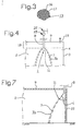
- Figure 5 illustrates what is happening at a prior art device.
- non-parallel partial air streams 6a are discharged, which instead are directed partially towards each other, which means that said partial air streams 6a collide with each other and become turbulent.
- a wide turbulent zone 7a is generated around the clean-air zone 7 and outside thereof the air is subjected to substantial turbulence, which is shown with arrows.
- Figure 6 illustrates with a similar view what is happening at a device according to the invention.
- parallel partial air streams 6a are discharged or exhausted, which means that these do not disturb each other when they flow out and thereby, a laminar air flow is generated without turbulence close to the body 11 or farther out there from. This in turn results in that the turbulent zone 7a around the clean-air zone 7 becomes more narrow and the turbulence around it less.
- the partial air streams 6a close to the body 11 generate a microscopic laminar flow from each passage 16 which surprisingly results in a macroscopic, substantially less incorporation and mixing of surrounding air, which also results in that smaller amounts of surrounding air are drawn downwards in the premises 2.
- the passages 16 may have a length L which is 4-10 times greater than their width B and they may preferably have a length L which is 4-6 times their width B.
- the passages 16 are rectilinear or substantially rectilinear, and of uniform thickness. They preferably have the same or substantially the same diameter along their entire length L. Furthermore, they prefer ably all have the same shape and preferably the same length.
- the portions 15 defining the passages form together a continuous, rigid outer part 13 and the passages 16 are preferably defined by tubes 17 which are located close beside each other, engage each other and are connected to each other.
- the tubes 17 are preferably made of a plastic material and they are connected to each other preferably by fusing.
- the air permeable body 11 preferably has a cross-sectional shape in the form of parts of a circle or substantially a circle or primarily parts of a circle or substantially a circle, i.e. shapes as in figures 1 and 4 .
- Another suitable cross-sectional shape for the body 11 is a semicircular shape or substantially semi circular shape.
- Still another suitable cross-sectional shape for the body 11 is the shape of a quarter of a circle or substantially a quarter of a circle, i.e. a shape as in figure 7 , but the body 11 may have any other shape as parts of a circle or substantially a circle.
- the body 11 is shaped or designed as a spherical segment or substantially as a spherical segment.
- the intake air unit 5 may be located beneath an upper zone 18 of the premises 2, namely such an upper zone 18 closest to the ceiling 9 of the premises 2 in which impure air is gathered and from which the impure air is ventilated through at least one air exhaust or air outlet 19 which preferably is provided at the ceiling 9.
- the impure air from the upper zone 18 is not substantially coejected by the air streams 6 discharged by the air supply device 1.
- eventual turbulence in the upper zone 18 does not disturb the smooth flow of the air streams 6.
- the intake air unit 5 may be located above a door 20 to the premises 2 and it may be elongated and extend along at least a part of the width of the door 20. By locating the intake air unit 5 in this way, a curtain of clean air and/or cool air can be generated immediately within the door 20.
- a filter 21 In order to filtrate the air A before it is fed into the intake air unit 5, one can locate or mount a filter 21 in the air supply tube 8 or on any other suitable location.
- the tubes 17 may e.g. be made of a metallic material or of a ceramic material or any other suitable material instead of a plastic material
- the outer part 13 may be thicker than the inner part 12, at least the outer part 13 and preferably also the inner part 12 may consist of such heat resistant material that the air supply device 1 can substantially withstand fires and instead of an air outlet 19 located at the ceiling 9 of the premises 2, at least one air outlet (not shown) can be located down below in the premises 2.
- the air supply device 1 can be an intake air device with one or more intake air units 5 and/or be a device for air circulation.
- the device 23 can be a device taking in cool air and/or including a cooling device or be a cooling device for cooling air.
Landscapes
- Engineering & Computer Science (AREA)
- Chemical & Material Sciences (AREA)
- Combustion & Propulsion (AREA)
- Mechanical Engineering (AREA)
- General Engineering & Computer Science (AREA)
- Duct Arrangements (AREA)
- Exhaust Gas After Treatment (AREA)
- Compressor (AREA)
Claims (21)
- Luftzufuhrvorrichtung zum Erlangen von Zonen mit reiner Luft (7) in Räumlichkeiten, die Luftzufuhrvorrichtung (1) aufweisend mindestens ein luftdurchlässiges Gehäuse (11) mit mindestens einem inneren und mindestens einem äußeren Bauteil (12, 13), wobei das innere Bauteil (12) aus einem porösen Material besteht oder ein solches beinhaltet,- wobei mindestens eine Gebläsevorrichtung (22) zum Fördern von Luft (A) in die Räumlichkeiten und zum Durchströmen des luftdurchlässigen Gehäuses (11) bei niedriger Luftgeschwindigkeit bereitgestellt ist,- wobei mindestens eine Vorrichtung (23) bereitgestellt ist, die sicherstellt, dass die zu den Räumlichkeiten (2) geförderte Luft (A) eine niedrigere Temperatur aufweist als die Luft in den Räumlichkeiten (2) und- wobei der Querschnitt des luftdurchlässigen Gehäuses (11) die Form von Kreisteilen, im Wesentlichen die Form eines Kreises oder hauptsächlich die Form von Kreisteilen aufweist,dadurch gekennzeichnet, dass das innere Bauteil (12) aus einem porösen Material besteht oder ein solches beinhaltet und dass das äußere Bauteil (13) Durchtritte (16) aufweist, die im Wesentlichen geradlinig, von gleichmäßiger Dicke und nah beieinander angeordnet sind, wobei die Durchtritte (16) ferner eine Länge (L) aufweisen, die mindestens viermal größer als ihre Breite (B) ist, so dass geradlinige und gleichmäßig verteilte Teilluftströme (6a) generiert werden, um die turbulente Zone (7a) um die Reinluft-Zone (7) herum zu schmälern, so dass sich dabei die Turbulenz um die Reinluft-Zone (7) verringert.
- Luftzufuhrvorrichtung nach Anspruch 1,
dadurch gekennzeichnet, dass die Länge (L) jedes Durchtritts (16) 4-10 mal größer als ihre Breite (B) ist. - Luftzufuhrvorrichtung nach Anspruch 2,
dadurch gekennzeichnet, dass die Länge jedes Durchtritts (16) 4-6 mal größer als ihre Breite (B) ist. - Luftzufuluvorrichtung nach einem der vorhergehenden Ansprüche,
dadurch gekennzeichnet, dass sämtliche oder nahezu sämtliche Durchtritte (16) die gleich lang sind. - Luftzufuluvorrichtung nach einem der vorhergehenden Ansprüche,
dadurch gekennzeichnet, dass die Durchtritte (16) durch Röhren (17) definiert werden, die nahe beieinander angeordnet und miteinander verbunden sind. - Luftzufuhrvorrichtung nach Anspruch 5,
dadurch gekennzeichnet, dass die Röhren (17) aus einem Kunststoffmaterial bestehen. - Luftzufuhrvorrichtung nach Anspruch 5,
dadurch gekenntzeichnet, dass die Röhren (17) aus einem metallischen Material bestehen. - Luftzufuhrvorrichtung nach Anspruch 5,
dadurch gekennzeichnet, dass die Röhren (17) aus einem keramischen Material bestehen. - Luftzufuhrvorrichtung nach einem der Ansprüche, 5-7,
dadurch gekennzeichnet, dass die Röhren (17) durch Verschmelzung miteinander verbunden sind. - Luftzufuhrvorrichtung nach einem der vorhergehenden Ansprüche,
dadurch gekennzeichnet, dass das poröse Material (14) des inneren Bauteils (12) dazu ausgestaltet ist, eine Filtrierung der durch das poröse Material durchströmenden Luft zu erlauben, um einen niedrigen Partikelgehalt in den Räumlichkeiten (2) zu erlangen. - Luftzufuhrvorrichtung nach einem der vorhergehenden Ansprüche,
dadurch gekennzeichnet, dass das poröse Material (14) des inneren Bauteils (12) aus einem aufgeschäumten Kunststoff mit offenen Zellen besteht. - Luftzufuhrvorrichtung nach einem der vorhergehenden Ansprüche,
dadurch gekennzeichnet, dass das äußere Bauteil (13) dicker als das innere Bauteil (12) ist. - Luftzufuhsvorrichtung nach einem der vorhergehenden Ansprüche,
dadurch gekennzeichnet, dass das äußere Bauteil (13) aus einem hitzefesten Material besteht. - Luftzufuhrvorrichtung nach einem der vorhergehenden Ansprüche,
dadurch gekennzeichnet, dass das innere und das äußere Bauteil (12, 13) miteinander verbunden sind. - Luftzufuhrvorrichtung nach einem der vorhergehenden Ansprüche,
dadurch gekennzeichnet, dass der Querschnitt des Gehäuses (11) als Halbkreis oder im Wesentlichen als Halbkreis ausgeformt ist. - Luftzufuhrvorrichtung nach einem der Ansprüche 1-15,
dadurch gekennzeichnet, dass der Querschnitt des luftdurchlässigen Gehäuses (11) als Viertelkreis oder im Wesentlichen als Viertelkreis ausgeformt ist. - Luftzufuhrvorrichtung nach einem der Ansprüche 1-14,
dadurch gekennzeichnet, dass das luftdurchlässige Gehäuses (11) als Kugelsegment oder im Wesentlichen als Kugelsegment ausgeformt ist. - Luftzufultrvorrichtung nach einem der vorhergehenden Ansprüche,
dadurch gekennzeichnet, dass die Vorrichtung (23), die sicherstellt, dass die zu den Räumlichkeiten (2) geförderte Luft (A) eine niedrigere Temperatur aufweist als die Luft in den Räumlichkeiten (2), zum Fördern von Luft mit einer solchen Temperatur bereitgestellt ist, dass die Luft auf eine niedrige Höhe in den Räumlichkeiten (2) sinkt. - Luftzufuhrvorrichtung nach einem der vorhergehenden Ansprüche, wobei unreine Luft in einer oberen Zone (18), die sich am dichtesten an der Decke (9) befindet, gesammelt wird und wobei mindestens ein Luftauslass (19) für unreine Luft an der Decke (9) der Räumlichkeiten (2) bereitgestellt ist,
dadurch gekennzeichnet, dass das luftdurchlässige Gehäuse (11) unterhalb der oberen Zone (18) angeordnet ist, so dass im Wesentlichen keine unreine Luft aus der oberen Zone (18) durch die aus dem luftdurchlässigen Gehäuse abgegebenen Luftströme (6) vertrieben wird. - Luftzufuhrvorrichtung nach einem der vorhergehenden Ansprüche,
dadurch gekennzeichnet, dass das luftdurchlässige Gehäuse oberhalb einer Tür (20) zu den Räumlichkeiten (2) angeordnet ist, eine längliche Form aufweist und sich über mindestens einen Teil der Breite der Tür (20) erstreckt. - Luftzufittuvorrichtung nach einem der vorhergehenden Ansprüche,
dadurch gekennzeichnet, dass die Vorrichtung (23), die sicherstellt, dass die zu den Räumlichkeiten (2) geförderte Luft (A) eine niedrigere Temperatur aufweist als die Luft in den Räumlichkeiten (2), eine Vorrichtung zum Aufnehmen von kühler Luft ist und/oder eine Kühlvorrichtung aufweist oder eine Kühlvorrichtung zum Kühlen von Luft ist.
Applications Claiming Priority (2)
| Application Number | Priority Date | Filing Date | Title |
|---|---|---|---|
| SE0302201A SE0302201D0 (sv) | 2003-08-13 | 2003-08-13 | Lufttillförselanordning |
| PCT/SE2004/001182 WO2005017419A1 (en) | 2003-08-13 | 2004-08-12 | Air supply device |
Publications (2)
| Publication Number | Publication Date |
|---|---|
| EP1654501A1 EP1654501A1 (de) | 2006-05-10 |
| EP1654501B1 true EP1654501B1 (de) | 2009-10-14 |
Family
ID=27800879
Family Applications (1)
| Application Number | Title | Priority Date | Filing Date |
|---|---|---|---|
| EP04775304A Expired - Lifetime EP1654501B1 (de) | 2003-08-13 | 2004-08-12 | Luftzufuhrvorrichtung |
Country Status (7)
| Country | Link |
|---|---|
| US (1) | US20060252364A1 (de) |
| EP (1) | EP1654501B1 (de) |
| AT (1) | ATE445813T1 (de) |
| DE (1) | DE602004023618D1 (de) |
| ES (1) | ES2333433T3 (de) |
| SE (1) | SE0302201D0 (de) |
| WO (1) | WO2005017419A1 (de) |
Families Citing this family (13)
| Publication number | Priority date | Publication date | Assignee | Title |
|---|---|---|---|---|
| SE0401746D0 (sv) * | 2004-07-05 | 2004-07-05 | Camfil Ab | An air filter unit |
| SE532219C2 (sv) * | 2006-02-28 | 2009-11-17 | Airsonett Ab | Förfarande och anordning för att åstadkomma en renluftzon vid ett operationsområde inom sjukvården och användning av nämnda anordning |
| NL1032941C2 (nl) * | 2006-11-24 | 2008-05-27 | Bo Air Luchtbehandeling B V | Luchtverdeelelement voor een luchtkanaal en luchtbehandelingskanaal voorzien van een dergelijk luchtverdeelelement. |
| SE532217C2 (sv) * | 2007-05-03 | 2009-11-17 | Airsonett Ab | Ventilationsanordning för en operationslokal |
| GB0819534D0 (en) * | 2008-10-24 | 2008-12-03 | Marine Systems Technology Ltd | Noise reduction in ducted air systems |
| US20100120349A1 (en) * | 2008-10-31 | 2010-05-13 | Airsonett Ab | Surgical theater ventilating devices and methods |
| WO2010100559A1 (en) | 2009-03-05 | 2010-09-10 | Airsonett Ab | Surgical instrument table ventilation devices and methods |
| WO2011042801A1 (en) | 2009-10-07 | 2011-04-14 | Airsonett Ab | Methods and devices for displacing body convection and providing a controlled personal breathing zone |
| EP2547964B1 (de) | 2010-03-16 | 2016-04-13 | Airsonett AB | Behandlung von asthma, allergischer rhinitis und verbesserung der schlafqualität durch temperaturgesteuerte laminare luftstrombehandlung |
| ES2545693T3 (es) | 2011-04-06 | 2015-09-15 | Airsonett Ab | Dispositivo de flujo de aire laminar controlado por temperatura |
| ES2699902T3 (es) * | 2013-12-03 | 2019-02-13 | Avidicare Ab | Un sistema de suministro de aire |
| WO2019206385A2 (en) | 2018-04-24 | 2019-10-31 | Tiny Wolf Ivs | A diffuser head and an air cleaning apparatus comprising same |
| EP4228580A1 (de) * | 2020-10-14 | 2023-08-23 | Airsonett AB | Verbesserte vorrichtung zur bereitstellung einer reinluftzone, z. b. einer gesteuerten persönlichen atemzone |
Family Cites Families (19)
| Publication number | Priority date | Publication date | Assignee | Title |
|---|---|---|---|---|
| DE2608792A1 (de) | 1976-03-03 | 1977-09-08 | Josef Piederstorfer | Mehrfachduese zur erzeugung radialer verdraengungsstroemungen |
| DE4014795C1 (en) * | 1990-05-09 | 1992-02-06 | Daldrop & Dr. Ing. Huber Gmbh & Co, 7441 Neckartailfingen, De | Clean room or operating theatre - incorporates laminar flow ceiling outlets for clean air |
| SE500707C2 (sv) * | 1990-08-22 | 1994-08-15 | Jk Vvs Projektering Ab | Tilluftdon med halvsfärisk utströmningsdel uppvisande poröst material |
| PT501725E (pt) * | 1991-03-01 | 2001-10-31 | Procter & Gamble | Pulverizacao de liquidos |
| US5221348A (en) * | 1991-11-26 | 1993-06-22 | Masano Thomas C | High pressure glue injector |
| SE506210C2 (sv) * | 1994-09-01 | 1997-11-24 | Kurt Belin | Tilluftsdon med donfront innefattande bärande skikt av väv samt ett på väven uppburet strömningsriktande skikt |
| US6214303B1 (en) * | 1995-01-20 | 2001-04-10 | Engelhard Corporation | Method and apparatus for treating the atmosphere |
| US5858469A (en) * | 1995-11-30 | 1999-01-12 | Sermatech International, Inc. | Method and apparatus for applying coatings using a nozzle assembly having passageways of differing diameter |
| NO310792B1 (no) | 1996-01-30 | 2001-08-27 | Hesco Pilgersteg Ag | Luftutlöp |
| JP3739486B2 (ja) * | 1996-06-13 | 2006-01-25 | 富士通株式会社 | 屋外設置型キャビネット |
| DE19625987A1 (de) * | 1996-06-28 | 1998-01-02 | Bayer Ag | Verfahren zur kontinuierlichen Herstellung von thermoplastisch verarbeitbaren Polyurethanen mit verbessertem Verarbeitungsverhalten |
| US5976220A (en) * | 1996-12-09 | 1999-11-02 | 3M Innovative Properties Company | Diffusional gas transfer system and method using same |
| US5716268A (en) * | 1997-02-18 | 1998-02-10 | Plymovent Ab | Device for removal of deleterious impurities from room atmosphere |
| US6132318A (en) * | 1997-07-01 | 2000-10-17 | Scs Interactive, Inc. | Interactive funhouse play structure |
| US5928076C1 (en) * | 1997-09-25 | 2001-04-24 | Hewlett Packard Co | Emi-attenuating air ventilation panel |
| DE19958659A1 (de) * | 1999-12-06 | 2001-06-07 | Duerr Systems Gmbh | Kabine |
| SE516775C2 (sv) * | 2000-06-05 | 2002-02-26 | Jan Kristensson | Förfarande och anordning för att åstadkoma ren luft i en lokal |
| US6368207B1 (en) * | 2000-08-25 | 2002-04-09 | Delphi Technologies, Inc. | Automotive heating, ventilating and air conditioning module with improved air mixing |
| DE10058721C2 (de) * | 2000-11-25 | 2002-11-28 | Draeger Medical Ag | Operationsleuchte an einem Deckenarmsystem |
-
2003
- 2003-08-13 SE SE0302201A patent/SE0302201D0/xx unknown
-
2004
- 2004-08-12 WO PCT/SE2004/001182 patent/WO2005017419A1/en not_active Ceased
- 2004-08-12 EP EP04775304A patent/EP1654501B1/de not_active Expired - Lifetime
- 2004-08-12 ES ES04775304T patent/ES2333433T3/es not_active Expired - Lifetime
- 2004-08-12 DE DE602004023618T patent/DE602004023618D1/de not_active Expired - Lifetime
- 2004-08-12 US US10/567,914 patent/US20060252364A1/en not_active Abandoned
- 2004-08-12 AT AT04775304T patent/ATE445813T1/de not_active IP Right Cessation
Also Published As
| Publication number | Publication date |
|---|---|
| EP1654501A1 (de) | 2006-05-10 |
| DE602004023618D1 (de) | 2009-11-26 |
| ES2333433T3 (es) | 2010-02-22 |
| WO2005017419A1 (en) | 2005-02-24 |
| US20060252364A1 (en) | 2006-11-09 |
| ATE445813T1 (de) | 2009-10-15 |
| SE0302201D0 (sv) | 2003-08-13 |
Similar Documents
| Publication | Publication Date | Title |
|---|---|---|
| US20060252364A1 (en) | Air supply device | |
| CN101784248B (zh) | 用于提供清洁空气区的通风设备 | |
| EP2881675B1 (de) | Luftzuführungssystem | |
| US5167577A (en) | Intake air unit | |
| SE0901265A1 (sv) | Kylbaffel med VAV-funktion via reglerskena | |
| SE532219C2 (sv) | Förfarande och anordning för att åstadkomma en renluftzon vid ett operationsområde inom sjukvården och användning av nämnda anordning | |
| JP2019519710A (ja) | 送風機 | |
| JP4185820B2 (ja) | 吹出口およびそれを使用した空調方法 | |
| JPH11223378A (ja) | 空気調和設備用吹出し口 | |
| CN1333216C (zh) | 低温空调用排气口 | |
| JPH0666439A (ja) | クリーンルーム及びエアサプライユニット | |
| JP4480833B2 (ja) | 吹出口装置 | |
| JP3793854B2 (ja) | 多層コーン形結露防止吹出口装置 | |
| JP6329749B2 (ja) | 吹出ノズル | |
| JP3808567B2 (ja) | クリーンルーム構造 | |
| KR101702223B1 (ko) | 균등한 분배기능을 갖는 철도차량용 덕트 | |
| JP4671543B2 (ja) | 空調用吹出口 | |
| JPH10220856A (ja) | 空調機用吹出し装置 | |
| JP2005127532A (ja) | 吹出口装置 | |
| CN210118949U (zh) | 空调器的导风板和空调器 | |
| JPH07324801A (ja) | 吹出しグリル | |
| JP3271875B2 (ja) | クリーンルームの空気吹き出し用ダクト | |
| JP2000074473A (ja) | 低温及び高温給気を兼用する誘引型吹出装置 | |
| EP2409089B1 (de) | Luftzufuhrvorrichtung | |
| CN104896703B (zh) | 一种适用于冬夏温差较大区域的冬夏两用送风口 |
Legal Events
| Date | Code | Title | Description |
|---|---|---|---|
| PUAI | Public reference made under article 153(3) epc to a published international application that has entered the european phase |
Free format text: ORIGINAL CODE: 0009012 |
|
| 17P | Request for examination filed |
Effective date: 20060125 |
|
| AK | Designated contracting states |
Kind code of ref document: A1 Designated state(s): AT BE BG CH CY CZ DE DK EE ES FI FR GB GR HU IE IT LI LU MC NL PL PT RO SE SI SK TR |
|
| DAX | Request for extension of the european patent (deleted) | ||
| RAP1 | Party data changed (applicant data changed or rights of an application transferred) |
Owner name: AIRSONETT AB |
|
| 17Q | First examination report despatched |
Effective date: 20081107 |
|
| GRAP | Despatch of communication of intention to grant a patent |
Free format text: ORIGINAL CODE: EPIDOSNIGR1 |
|
| GRAS | Grant fee paid |
Free format text: ORIGINAL CODE: EPIDOSNIGR3 |
|
| GRAA | (expected) grant |
Free format text: ORIGINAL CODE: 0009210 |
|
| AK | Designated contracting states |
Kind code of ref document: B1 Designated state(s): AT BE BG CH CY CZ DE DK EE ES FI FR GB GR HU IE IT LI LU MC NL PL PT RO SE SI SK TR |
|
| REG | Reference to a national code |
Ref country code: GB Ref legal event code: FG4D |
|
| REG | Reference to a national code |
Ref country code: CH Ref legal event code: EP |
|
| REG | Reference to a national code |
Ref country code: IE Ref legal event code: FG4D |
|
| REF | Corresponds to: |
Ref document number: 602004023618 Country of ref document: DE Date of ref document: 20091126 Kind code of ref document: P |
|
| REG | Reference to a national code |
Ref country code: SE Ref legal event code: TRGR |
|
| REG | Reference to a national code |
Ref country code: ES Ref legal event code: FG2A Ref document number: 2333433 Country of ref document: ES Kind code of ref document: T3 |
|
| NLV1 | Nl: lapsed or annulled due to failure to fulfill the requirements of art. 29p and 29m of the patents act | ||
| PG25 | Lapsed in a contracting state [announced via postgrant information from national office to epo] |
Ref country code: FI Free format text: LAPSE BECAUSE OF FAILURE TO SUBMIT A TRANSLATION OF THE DESCRIPTION OR TO PAY THE FEE WITHIN THE PRESCRIBED TIME-LIMIT Effective date: 20091014 Ref country code: PT Free format text: LAPSE BECAUSE OF FAILURE TO SUBMIT A TRANSLATION OF THE DESCRIPTION OR TO PAY THE FEE WITHIN THE PRESCRIBED TIME-LIMIT Effective date: 20100215 |
|
| PG25 | Lapsed in a contracting state [announced via postgrant information from national office to epo] |
Ref country code: SI Free format text: LAPSE BECAUSE OF FAILURE TO SUBMIT A TRANSLATION OF THE DESCRIPTION OR TO PAY THE FEE WITHIN THE PRESCRIBED TIME-LIMIT Effective date: 20091014 Ref country code: PL Free format text: LAPSE BECAUSE OF FAILURE TO SUBMIT A TRANSLATION OF THE DESCRIPTION OR TO PAY THE FEE WITHIN THE PRESCRIBED TIME-LIMIT Effective date: 20091014 |
|
| PG25 | Lapsed in a contracting state [announced via postgrant information from national office to epo] |
Ref country code: AT Free format text: LAPSE BECAUSE OF FAILURE TO SUBMIT A TRANSLATION OF THE DESCRIPTION OR TO PAY THE FEE WITHIN THE PRESCRIBED TIME-LIMIT Effective date: 20091014 Ref country code: BE Free format text: LAPSE BECAUSE OF FAILURE TO SUBMIT A TRANSLATION OF THE DESCRIPTION OR TO PAY THE FEE WITHIN THE PRESCRIBED TIME-LIMIT Effective date: 20091014 |
|
| PG25 | Lapsed in a contracting state [announced via postgrant information from national office to epo] |
Ref country code: RO Free format text: LAPSE BECAUSE OF FAILURE TO SUBMIT A TRANSLATION OF THE DESCRIPTION OR TO PAY THE FEE WITHIN THE PRESCRIBED TIME-LIMIT Effective date: 20091014 Ref country code: EE Free format text: LAPSE BECAUSE OF FAILURE TO SUBMIT A TRANSLATION OF THE DESCRIPTION OR TO PAY THE FEE WITHIN THE PRESCRIBED TIME-LIMIT Effective date: 20091014 Ref country code: BG Free format text: LAPSE BECAUSE OF FAILURE TO SUBMIT A TRANSLATION OF THE DESCRIPTION OR TO PAY THE FEE WITHIN THE PRESCRIBED TIME-LIMIT Effective date: 20100114 Ref country code: DK Free format text: LAPSE BECAUSE OF FAILURE TO SUBMIT A TRANSLATION OF THE DESCRIPTION OR TO PAY THE FEE WITHIN THE PRESCRIBED TIME-LIMIT Effective date: 20091014 |
|
| PLBE | No opposition filed within time limit |
Free format text: ORIGINAL CODE: 0009261 |
|
| STAA | Information on the status of an ep patent application or granted ep patent |
Free format text: STATUS: NO OPPOSITION FILED WITHIN TIME LIMIT |
|
| PG25 | Lapsed in a contracting state [announced via postgrant information from national office to epo] |
Ref country code: SK Free format text: LAPSE BECAUSE OF FAILURE TO SUBMIT A TRANSLATION OF THE DESCRIPTION OR TO PAY THE FEE WITHIN THE PRESCRIBED TIME-LIMIT Effective date: 20091014 Ref country code: CZ Free format text: LAPSE BECAUSE OF FAILURE TO SUBMIT A TRANSLATION OF THE DESCRIPTION OR TO PAY THE FEE WITHIN THE PRESCRIBED TIME-LIMIT Effective date: 20091014 |
|
| 26N | No opposition filed |
Effective date: 20100715 |
|
| PG25 | Lapsed in a contracting state [announced via postgrant information from national office to epo] |
Ref country code: GR Free format text: LAPSE BECAUSE OF FAILURE TO SUBMIT A TRANSLATION OF THE DESCRIPTION OR TO PAY THE FEE WITHIN THE PRESCRIBED TIME-LIMIT Effective date: 20100115 |
|
| PG25 | Lapsed in a contracting state [announced via postgrant information from national office to epo] |
Ref country code: MC Free format text: LAPSE BECAUSE OF NON-PAYMENT OF DUE FEES Effective date: 20100831 |
|
| REG | Reference to a national code |
Ref country code: CH Ref legal event code: PL |
|
| PG25 | Lapsed in a contracting state [announced via postgrant information from national office to epo] |
Ref country code: LI Free format text: LAPSE BECAUSE OF NON-PAYMENT OF DUE FEES Effective date: 20100831 Ref country code: CH Free format text: LAPSE BECAUSE OF NON-PAYMENT OF DUE FEES Effective date: 20100831 |
|
| PG25 | Lapsed in a contracting state [announced via postgrant information from national office to epo] |
Ref country code: IE Free format text: LAPSE BECAUSE OF NON-PAYMENT OF DUE FEES Effective date: 20100812 |
|
| PG25 | Lapsed in a contracting state [announced via postgrant information from national office to epo] |
Ref country code: CY Free format text: LAPSE BECAUSE OF FAILURE TO SUBMIT A TRANSLATION OF THE DESCRIPTION OR TO PAY THE FEE WITHIN THE PRESCRIBED TIME-LIMIT Effective date: 20091014 |
|
| PG25 | Lapsed in a contracting state [announced via postgrant information from national office to epo] |
Ref country code: NL Free format text: LAPSE BECAUSE OF FAILURE TO SUBMIT A TRANSLATION OF THE DESCRIPTION OR TO PAY THE FEE WITHIN THE PRESCRIBED TIME-LIMIT Effective date: 20091014 Ref country code: LU Free format text: LAPSE BECAUSE OF NON-PAYMENT OF DUE FEES Effective date: 20100812 Ref country code: HU Free format text: LAPSE BECAUSE OF FAILURE TO SUBMIT A TRANSLATION OF THE DESCRIPTION OR TO PAY THE FEE WITHIN THE PRESCRIBED TIME-LIMIT Effective date: 20100415 |
|
| REG | Reference to a national code |
Ref country code: DE Ref legal event code: R082 Ref document number: 602004023618 Country of ref document: DE Representative=s name: TBK, DE |
|
| PG25 | Lapsed in a contracting state [announced via postgrant information from national office to epo] |
Ref country code: TR Free format text: LAPSE BECAUSE OF FAILURE TO SUBMIT A TRANSLATION OF THE DESCRIPTION OR TO PAY THE FEE WITHIN THE PRESCRIBED TIME-LIMIT Effective date: 20091014 |
|
| REG | Reference to a national code |
Ref country code: GB Ref legal event code: 732E Free format text: REGISTERED BETWEEN 20121101 AND 20121107 |
|
| REG | Reference to a national code |
Ref country code: DE Ref legal event code: R081 Ref document number: 602004023618 Country of ref document: DE Owner name: AIRSONETT AB, SE Free format text: FORMER OWNER: AIRSONETT AB, AENGELHOLM, SE Effective date: 20121022 Ref country code: DE Ref legal event code: R082 Ref document number: 602004023618 Country of ref document: DE Representative=s name: TBK, DE Effective date: 20121022 |
|
| REG | Reference to a national code |
Ref country code: FR Ref legal event code: TP Owner name: AIRSONETT AB, SE Effective date: 20130418 |
|
| REG | Reference to a national code |
Ref country code: FR Ref legal event code: PLFP Year of fee payment: 13 |
|
| REG | Reference to a national code |
Ref country code: FR Ref legal event code: ST Effective date: 20160429 |
|
| REG | Reference to a national code |
Ref country code: FR Ref legal event code: RN Effective date: 20160613 |
|
| REG | Reference to a national code |
Ref country code: FR Ref legal event code: FC Effective date: 20160628 |
|
| PG25 | Lapsed in a contracting state [announced via postgrant information from national office to epo] |
Ref country code: FR Free format text: LAPSE BECAUSE OF NON-PAYMENT OF DUE FEES Effective date: 20150831 |
|
| PGRI | Patent reinstated in contracting state [announced from national office to epo] |
Ref country code: FR Effective date: 20160705 |
|
| REG | Reference to a national code |
Ref country code: FR Ref legal event code: PLFP Year of fee payment: 14 |
|
| PGFP | Annual fee paid to national office [announced via postgrant information from national office to epo] |
Ref country code: FR Payment date: 20170803 Year of fee payment: 14 Ref country code: IT Payment date: 20170828 Year of fee payment: 14 Ref country code: ES Payment date: 20170901 Year of fee payment: 14 Ref country code: DE Payment date: 20170831 Year of fee payment: 14 Ref country code: GB Payment date: 20170803 Year of fee payment: 14 |
|
| PGFP | Annual fee paid to national office [announced via postgrant information from national office to epo] |
Ref country code: SE Payment date: 20170803 Year of fee payment: 14 |
|
| REG | Reference to a national code |
Ref country code: DE Ref legal event code: R119 Ref document number: 602004023618 Country of ref document: DE |
|
| REG | Reference to a national code |
Ref country code: SE Ref legal event code: EUG |
|
| GBPC | Gb: european patent ceased through non-payment of renewal fee |
Effective date: 20180812 |
|
| PG25 | Lapsed in a contracting state [announced via postgrant information from national office to epo] |
Ref country code: SE Free format text: LAPSE BECAUSE OF NON-PAYMENT OF DUE FEES Effective date: 20180813 |
|
| PG25 | Lapsed in a contracting state [announced via postgrant information from national office to epo] |
Ref country code: IT Free format text: LAPSE BECAUSE OF NON-PAYMENT OF DUE FEES Effective date: 20180812 Ref country code: DE Free format text: LAPSE BECAUSE OF NON-PAYMENT OF DUE FEES Effective date: 20190301 |
|
| PG25 | Lapsed in a contracting state [announced via postgrant information from national office to epo] |
Ref country code: FR Free format text: LAPSE BECAUSE OF NON-PAYMENT OF DUE FEES Effective date: 20180831 |
|
| REG | Reference to a national code |
Ref country code: ES Ref legal event code: FD2A Effective date: 20190918 |
|
| PG25 | Lapsed in a contracting state [announced via postgrant information from national office to epo] |
Ref country code: GB Free format text: LAPSE BECAUSE OF NON-PAYMENT OF DUE FEES Effective date: 20180812 Ref country code: ES Free format text: LAPSE BECAUSE OF NON-PAYMENT OF DUE FEES Effective date: 20180813 |