EP1654931A2 - Générateur de vapeur pour un four à vapeur - Google Patents
Générateur de vapeur pour un four à vapeur Download PDFInfo
- Publication number
- EP1654931A2 EP1654931A2 EP05020714A EP05020714A EP1654931A2 EP 1654931 A2 EP1654931 A2 EP 1654931A2 EP 05020714 A EP05020714 A EP 05020714A EP 05020714 A EP05020714 A EP 05020714A EP 1654931 A2 EP1654931 A2 EP 1654931A2
- Authority
- EP
- European Patent Office
- Prior art keywords
- steam
- water
- cooking chamber
- pipe
- steam generator
- Prior art date
- Legal status (The legal status is an assumption and is not a legal conclusion. Google has not performed a legal analysis and makes no representation as to the accuracy of the status listed.)
- Granted
Links
Images




Classifications
-
- F—MECHANICAL ENGINEERING; LIGHTING; HEATING; WEAPONS; BLASTING
- F24—HEATING; RANGES; VENTILATING
- F24C—DOMESTIC STOVES OR RANGES ; DETAILS OF DOMESTIC STOVES OR RANGES, OF GENERAL APPLICATION
- F24C7/00—Stoves or ranges heated by electric energy
- F24C7/06—Arrangement or mounting of electric heating elements
-
- F—MECHANICAL ENGINEERING; LIGHTING; HEATING; WEAPONS; BLASTING
- F24—HEATING; RANGES; VENTILATING
- F24C—DOMESTIC STOVES OR RANGES ; DETAILS OF DOMESTIC STOVES OR RANGES, OF GENERAL APPLICATION
- F24C15/00—Details
- F24C15/32—Arrangements of ducts for hot gases, e.g. in or around baking ovens
- F24C15/322—Arrangements of ducts for hot gases, e.g. in or around baking ovens with forced circulation
- F24C15/327—Arrangements of ducts for hot gases, e.g. in or around baking ovens with forced circulation with air moisturising
-
- A—HUMAN NECESSITIES
- A21—BAKING; EDIBLE DOUGHS
- A21B—BAKERS' OVENS; MACHINES OR EQUIPMENT FOR BAKING
- A21B3/00—Parts or accessories of ovens
- A21B3/04—Air-treatment devices for ovens, e.g. regulating humidity
-
- F—MECHANICAL ENGINEERING; LIGHTING; HEATING; WEAPONS; BLASTING
- F24—HEATING; RANGES; VENTILATING
- F24C—DOMESTIC STOVES OR RANGES ; DETAILS OF DOMESTIC STOVES OR RANGES, OF GENERAL APPLICATION
- F24C15/00—Details
-
- A—HUMAN NECESSITIES
- A47—FURNITURE; DOMESTIC ARTICLES OR APPLIANCES; COFFEE MILLS; SPICE MILLS; SUCTION CLEANERS IN GENERAL
- A47J—KITCHEN EQUIPMENT; COFFEE MILLS; SPICE MILLS; APPARATUS FOR MAKING BEVERAGES
- A47J27/00—Cooking-vessels
- A47J27/04—Cooking-vessels for cooking food in steam; Devices for extracting fruit juice by means of steam ; Vacuum cooking vessels
- A47J2027/043—Cooking-vessels for cooking food in steam; Devices for extracting fruit juice by means of steam ; Vacuum cooking vessels for cooking food in steam
Definitions
- the present invention relates to a steam oven for cooking food using steam, and more particularly to a steam generator for a steam oven, which generates steam of a high temperature and supplies the steam to the inside of a cooking chamber.
- steam ovens cook food using steam to make various dishes, such as steamed dishes.
- FIG. 1 is a schematic perspective view of a steam oven having a conventional steam generator
- FIG. 2 is a sectional view of the steam oven shown in FIG. 1.
- the steam oven comprises a cabinet 10, a cooking chamber 12 installed in the cabinet 10, and a door 14 for opening and closing the cooking chamber 12.
- a control panel 16 provided with various operating switches and display devices, is installed on the lower part of the front surface of the cabinet 10.
- the steam generator provided in the steam oven includes a water injection unit 21 inserted into the control panel 16 toward the inside of the cabinet 10, a steam generation unit 30 installed on the bottom of the inside of the cabinet 10 for generating steam, and a water supply pipe 25 connected between the water injection unit 21 and the steam generation unit 30.
- a heater 32 for heating water is installed in the steam generation unit 30, and a convection fan 35 for circulating air in the cooking chamber 12 and a convection heater 37 for heating the air in the cooking chamber 12 are installed in the rear part of the cooking chamber 12. That is, the convection fan 35 is operated in the cooking chamber 12 based on the cooking method to induce the uniform distribution of steam, and, if necessary, the convection heater 37 is operated to increase the temperature of the steam so that the cooking of food in the cooking chamber 12 can be performed at a high temperature.
- the supplied water passes through the water supply pipe 25 by gravity and is introduced into the steam generation unit 30 having the heater 32. Then, the water is heated by the heater 32, thereby generating steam. The generated steam flows into the cooking chamber 12, and is circulated by the convection fan 35, thereby cooking food placed in the cooking chamber 12.
- the conventional steam oven shown in FIGS. 1 and 2 is structured such that the steam generation unit 30 is installed in the cooking chamber 12.
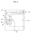
- another conventional steam oven which is shown in FIG. 3, is structured such that a steam generation unit 30' is installed outside a cooking chamber 12' and steam generated from the steam generation unit 30' is introduced into the cooking chamber 12' to cook food placed in the cooking chamber 12'.
- reference numeral 21' represents a water injection unit
- reference numeral 25' represents a water supply pipe
- reference numeral 32' represents a heater
- reference numerals 33 and 34 respectively represent a steam inlet pipe and a steam inlet port for supplying steam into the cooking chamber 12'
- reference numeral 35' represents a convection fan.
- the conventional steam generators 30 and 30' of the conventional steam ovens heat water using the heaters 32 and 32' to generate steam under the condition that the steam generation units 30 and 30' store the water, the conventional steam generators 30 and 30' are disadvantageous in that the time to generate the steam is long and the heaters 32 and 32' have large capacities.
- the steam generation unit 30' when the steam generation unit 30' is installed outside the cooking chamber 12', as shown in FIG. 3, the overall size of the steam oven is increased but the size of the cooking chamber 12' is relatively decreased, and the independent external steam generation unit 30' causes the complication of the structure of the steam oven and problems in insulating the steam oven.
- the present invention has been made in view of the above problems, and it is an object of the present invention to provide a steam generator for a steam oven, in which a heater is installed in a steam pipe supplying water from a water tank therethrough so that steam can be rapidly generated just when the water passes through the pipe, thereby shortening the cooking time and minimizing the size of the steam oven.
- a steam generator for a steam oven comprising a water injection unit for supplying water from the outside to the steam generator therethrough; a water tank installed outside a cooking chamber for storing the water supplied through the water injection unit; a flow adjusting unit installed at an outlet of the water tank for adjusting the quantity of the supplied water; a steam pipe connected between the flow adjusting unit and the cooking chamber for changing the water therein into steam and supplying the steam to the inside of the cooking chamber; and a heater installed in the steam pipe for heating the water supplied to the inside of the steam pipe.
- the water injection unit is a sliding type in which a water injection box slidably moves towards the inside and outside of a cabinet.
- the water tank includes a slim-structured tank main body, and a lid covering the upper end of the tank main body.
- the steam pipe includes an inlet and an outlet formed at both upper ends thereof, and is bent at least one time at a portion thereof between the inlet and the outlet.
- the steam pipe has a U-shaped structure.
- the outlet of the steam pipe is positioned at a higher level than the inlet of the steam pipe.
- the heater is bent in the same structure as that of the steam pipe.
- the flow adjusting unit is a solenoid valve installed at the outlet of the water tank.
- a steam generator for a steam oven comprising a water injection unit for supplying water from the outside to the steam generator therethrough; a steam pipe connected between the water injection unit and a cooking chamber for changing the water therein into steam and supplying the steam to the inside of the cooking chamber; and a heater installed in the steam pipe for heating the water supplied to the inside of the steam pipe.
- a steam oven comprising a cooking chamber installed in a cabinet; a water injection unit installed in the cabinet for supplying water from the outside therethrough; a water tank installed outside the cooking chamber for storing the water supplied through the water injection unit; a flow adjusting unit installed at an outlet of the water tank for adjusting the quantity of the supplied water; a steam pipe connected between the flow adjusting unit and the cooking chamber for changing the water therein into steam; a heater installed in the steam pipe for heating the water supplied to the inside of the steam pipe; and a steam supply pipe for connecting the steam pipe to the inside of the cooking chamber.
- the steam generator of the present invention reduces the overall size of the oven, thereby relatively increasing the size of the cooking chamber.
- the steam generator of the present invention rapidly generates steam without increasing the capacity of the heater, thereby shortening the overall cooking time.
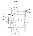
- FIGS. 4 to 7 illustrate a steam oven having a steam generator in accordance with the present invention. More specifically, FIG. 4 is a sectional view of the steam oven, FIG. 5 is a front view of the steam oven, FIG. 6 is an exploded perspective view of an essential part of the steam generator illustrating a water tank and a steam supply pipe, and FIG. 7 is a sectional view taken along the line A-A of FIG. 6.
- the steam generator of the present invention comprises a water injection unit 60 connected from the upper part of a cabinet 50, provided with a control-operating unit 56 formed thereon, to the inner part of the cabinet 50 for supplying water from the outside to the inside of the cabinet 50, a water tank 70 connected to the water injection unit 60 by a water supply pipe 62 for discharging a designated quantity of water under the condition that the water tank 70 stores the water supplied through the water injection unit 60, and a steam generation unit 80 for heating the water supplied from the water tank 70 to generate steam and supply the steam to the inside of a cooking chamber 52.
- the water injection unit 60 is a sliding type in which a water injection box slidably moves towards the inside and outside of the cabinet 50.
- the water tank 70 has a slim structure, the width of which is short, and, the length of which is long, and is positioned outside the cooking chamber 52.
- the water tank 70 includes a tank main body 71, and a lid 73 covering the upper end of the tank main body 71.
- a solenoid valve 75 serving as a flow adjusting unit for adjusting the quantity of the water discharged to the steam generation unit 80, is installed in an outlet of the water tank 70.
- the solenoid valve 75 is adjusted manually or automatically by a controller provided on the control-operating unit 56.
- the steam generation unit 80 has a long pipe structure, as shown in FIG. 6, so that the water supplied from the water tank 70 is heated by a heater 83 and changed to steam when the water flows in the steam generation unit 80.
- the steam generation unit 80 includes a steam pipe 81 connected to the solenoid valve 75 provided at the outlet of the water tank 70 for receiving water, the heater 83 inserted into the steam pipe 81 in the longitudinal direction for heating the water therein, and a steam supply pipe 85 connected between the steam pipe 81 and the inside of the cooking chamber 52.
- the steam pipe 81 includes an inlet 81a formed at one upper end thereof and connected to the water tank 70 or the solenoid valve 75, and an outlet 81b formed at the other upper end thereof and connected to the steam supply pipe 85.
- the steam pipe 81 is bent at least one time at the portion thereof between the inlet 81a and the outlet 81b. This embodiment illustrates the steam pipe 81 bent in a U shape.
- the outlet 81b is positioned at a level higher than the inlet 81a so that the steam is smoothly discharged to the outside of the steam pipe 81 through the outlet 81b.
- the heater 83 is bent in the same shape as that of the steam pipe 81 so that the heater 83 passes through the steam pipe 81.
- the heater 83 is bent also in a U shape.
- Heater terminals 84 and a heater controller 85 are positioned on both upper ends of the heater 83.
- a convection fan 91 for circulating air in the cooking chamber 52 is positioned in the cooking chamber 52, and a convection heater 93 for heating the air in the cooking chamber 52 is provided around the convection fan 91.
- a temperature sensor 95 for sensing the temperature of the inside of the cooking chamber 52 to control the operations of the heater 83 of the steam generation unit 80 and the convection heater 93 is installed at one side surface of the inside of the cooking chamber 52.
- a designated quantity of the water introduced into the water tank 70 is introduced into the steam pipe 81 according to the opening degree of the solenoid valve 75, and the small quantity of the water introduced into the steam pipe 71 is heated by the heater 83 and rapidly changed into steam.
- the steam is introduced into the cooking chamber 52.
- the steam generation unit 80 momentarily changes the small quantity of the water flowing the steam pipe 81 into steam using the heater 83 installed in the steam pipe 81, and supplies the steam to the inside of the cooking chamber 52 through a hole 88 communicated with the inside of the cooking chamber 52.
- the convection fan 91 installed in the cooking chamber 52 is operated to uniformly distribute the steam introduced into the cooking chamber 52, or the convection heater 93 is operated to increase the temperature of the steam according to the cooking methods so that food in the cooking chamber 52 can be cooked at a high temperature.
- the temperature sensor 95 positioned in the cooking chamber 52 senses the temperature of the inside of the cooking chamber 52 to cause the control-operating unit 56 to adjust the output of the heater 83 of the steam generation unit 80 or the convection heater 93 in the cooking chamber 52, thereby adjusting the temperature of the inside of the cooking chamber 52 to a desired temperature so that the food in the cooking chamber 52 can be cooked at the desired temperature. Further, the control-operating unit 56 can adjust the opening degree of the solenoid valve 75, thereby properly adjusting the quantity of the water supplied to the steam pipe 81.
- the present invention provides a steam generator for a steam oven, in which a slim-type water tank is installed outside a cooking chamber and water passing through a steam pipe is heated to generate steam, thereby reducing the overall size of the oven to relatively increase the size of the cooking chamber.
- the steam generator of the present invention rapidly generates the steam without increasing the capacity of a heater, thereby shortening the overall cooking time.
Landscapes
- Engineering & Computer Science (AREA)
- Chemical & Material Sciences (AREA)
- Combustion & Propulsion (AREA)
- Mechanical Engineering (AREA)
- General Engineering & Computer Science (AREA)
- Life Sciences & Earth Sciences (AREA)
- Food Science & Technology (AREA)
- Cookers (AREA)
- Commercial Cooking Devices (AREA)
Applications Claiming Priority (1)
| Application Number | Priority Date | Filing Date | Title |
|---|---|---|---|
| KR1020040089904A KR100629336B1 (ko) | 2004-11-05 | 2004-11-05 | 스팀 오븐의 증기 발생 장치 |
Publications (3)
| Publication Number | Publication Date |
|---|---|
| EP1654931A2 true EP1654931A2 (fr) | 2006-05-10 |
| EP1654931A3 EP1654931A3 (fr) | 2011-05-04 |
| EP1654931B1 EP1654931B1 (fr) | 2015-04-08 |
Family
ID=35735158
Family Applications (1)
| Application Number | Title | Priority Date | Filing Date |
|---|---|---|---|
| EP05020714.1A Expired - Lifetime EP1654931B1 (fr) | 2004-11-05 | 2005-09-22 | Générateur de vapeur pour un four à vapeur |
Country Status (6)
| Country | Link |
|---|---|
| US (1) | US20060096970A1 (fr) |
| EP (1) | EP1654931B1 (fr) |
| KR (1) | KR100629336B1 (fr) |
| AU (1) | AU2005204318A1 (fr) |
| CA (1) | CA2517613A1 (fr) |
| ZA (1) | ZA200508769B (fr) |
Cited By (9)
| Publication number | Priority date | Publication date | Assignee | Title |
|---|---|---|---|---|
| DE102006062069A1 (de) | 2006-12-29 | 2008-07-03 | BSH Bosch und Siemens Hausgeräte GmbH | Gargeräte-Dampferzeugungsvorrichtung mit wenigstens einem Durchlauferhitzer |
| WO2009000140A1 (fr) * | 2007-06-25 | 2008-12-31 | Xiaotian (Zhongshan) Industrial Co., Ltd. | Panier vapeur électrique en bambou |
| CN102755102A (zh) * | 2011-04-28 | 2012-10-31 | 三星电子株式会社 | 蒸汽烹饪设备及水位传感器控制方法 |
| EP2417880A4 (fr) * | 2009-04-06 | 2014-08-13 | Lg Electronics Inc | Procédé de commande d'un appareil de cuisson |
| EP3112765A1 (fr) * | 2015-06-29 | 2017-01-04 | Whirlpool Corporation | Système de génération de vapeur destiné à être utilisé dans un appareil de cuisson |
| EP3118528A1 (fr) * | 2015-07-14 | 2017-01-18 | Miele & Cie. KG | Appareil de cuisson et système de cuisson destiné à la cuisson et à aromatiser |
| EP2650615B1 (fr) | 2012-04-11 | 2018-01-10 | Electrolux Home Products Corporation N.V. | Four pour la cuisson de produits alimentaires |
| EP3248520A4 (fr) * | 2015-01-23 | 2018-09-05 | Balmuda Inc. | Dispositif de chauffage et de cuisson |
| WO2026024247A1 (fr) * | 2024-07-24 | 2026-01-29 | Renta Elektrikli Ev Aletleri Sanayi Ve Dis Ticaret Limited Sirketi | Appareil d'évent d'air pour fours à vapeur |
Families Citing this family (27)
| Publication number | Priority date | Publication date | Assignee | Title |
|---|---|---|---|---|
| KR100787746B1 (ko) * | 2006-06-19 | 2007-12-24 | 동양매직 주식회사 | 물통의 잔수 감지 구조를 갖는 스팀 오븐 |
| KR101041077B1 (ko) * | 2006-09-28 | 2011-06-13 | 삼성전자주식회사 | 스팀발생장치 및 이를 갖는 가열조리장치 |
| KR100824006B1 (ko) * | 2006-12-29 | 2008-04-24 | 엘지전자 주식회사 | 스팀 오븐의 스팀 발생장치 |
| US20100151092A1 (en) * | 2008-04-07 | 2010-06-17 | Sus Gerald A | Steam injection cooking device and method |
| US9066523B2 (en) * | 2009-01-19 | 2015-06-30 | Accutemp Products, Inc. | Method and apparatus for directing steam distribution in a steam cooker |
| IT1396249B1 (it) * | 2009-10-13 | 2012-11-16 | Giorik Spa | Procedimento combinato per la produzione di vapore in un forno di cottura a vapore per alimenti, e forno di cottura che realizza tale procedimento. |
| DE102009055148A1 (de) | 2009-12-22 | 2011-06-30 | BSH Bosch und Siemens Hausgeräte GmbH, 81739 | Dampferzeugungssystem für ein Haushaltsgerät und Verfahren zum Montieren eines solchen Dampferzeugungssystems |
| KR101860714B1 (ko) | 2011-04-28 | 2018-05-25 | 삼성전자주식회사 | 스팀조리기기 |
| CN103519705A (zh) * | 2012-07-04 | 2014-01-22 | 欣法食品股份有限公司 | 具有可分离蒸气装置的烤箱及其烘焙方法 |
| KR101370410B1 (ko) | 2012-08-24 | 2014-03-06 | 린나이코리아 주식회사 | 스팀 오븐의 유량제어 장치 및 그 유량제어 방법 |
| KR101981674B1 (ko) * | 2012-12-21 | 2019-05-24 | 삼성전자주식회사 | 조리기기 |
| JP6167333B2 (ja) * | 2013-05-08 | 2017-07-26 | パナソニックIpマネジメント株式会社 | 蒸気発生装置および加熱調理器 |
| CN103462519B (zh) * | 2013-08-21 | 2016-04-27 | 浙江安德电器有限公司 | 一种具有供水功能的蒸汽烤箱 |
| CN105333467A (zh) * | 2014-08-07 | 2016-02-17 | 广东美的厨房电器制造有限公司 | 烤箱 |
| KR20160134195A (ko) * | 2015-05-15 | 2016-11-23 | 최승현 | 순간 가열식 떡찜기 |
| WO2017111538A1 (fr) * | 2015-12-24 | 2017-06-29 | 정규태 | Récipient de cuisson à la vapeur |
| US10955142B2 (en) | 2018-07-03 | 2021-03-23 | Electrolux Home Products, Inc. | Cooking oven with steam generator inside cooking cavity |
| CN108937627A (zh) * | 2018-09-21 | 2018-12-07 | 广东新宝电器股份有限公司 | 一种带快速出蒸汽的煎烤锅 |
| CN109259044A (zh) * | 2018-09-26 | 2019-01-25 | 赵树广 | 一种蒸汽解冻柜 |
| EP3903042B1 (fr) | 2018-12-27 | 2024-07-03 | Arçelik Anonim Sirketi | Four doté d'une fonction de cuisson vapeur |
| US10813490B2 (en) * | 2019-01-31 | 2020-10-27 | Whirlpool Corporation | Water inlet connectivity for steam oven |
| KR102219330B1 (ko) * | 2019-12-11 | 2021-02-24 | 유한회사 마이더스 | 즉석 떡 조리장치 |
| CN111000456B (zh) * | 2019-12-31 | 2022-03-22 | 广东美的厨房电器制造有限公司 | 烤箱 |
| CN114305078B (zh) * | 2020-09-29 | 2023-05-02 | 杭州九阳小家电有限公司 | 一种快速出蒸汽的电蒸箱 |
| CN114468747B (zh) * | 2020-11-13 | 2026-04-24 | 浙江苏泊尔家电制造有限公司 | 烹饪器具和用于烹饪器具的烹饪方法 |
| KR102421938B1 (ko) * | 2020-12-11 | 2022-07-15 | 김봉수 | 스팀토스터기 |
| CN112806839B (zh) * | 2021-02-07 | 2021-11-09 | 珠海格力电器股份有限公司 | 一种蒸汽发生器控制方法、装置、蒸汽发生器及蒸烤箱 |
Citations (6)
| Publication number | Priority date | Publication date | Assignee | Title |
|---|---|---|---|---|
| JPS5459373A (en) | 1977-10-19 | 1979-05-12 | Matsushita Electric Industrial Co Ltd | Steam oven |
| EP0277337A2 (fr) | 1987-02-05 | 1988-08-10 | Electrolux-Juno Küchentechnik GmbH | Appareil à cuire ayant un espace à cuire chauffé par électricité et procédé pour opérer cet appareil à cuire |
| DE4403386C1 (de) | 1994-02-04 | 1995-06-01 | Wiesheu Wiwa Gmbh | Vorrichtung zur Wärmebehandlung von Lebensmitteln |
| JPH094849A (ja) | 1995-06-22 | 1997-01-10 | Matsushita Electric Ind Co Ltd | 加熱調理装置 |
| US6100502A (en) | 1998-10-28 | 2000-08-08 | Wing Shing Products (Bvi) Co. Ltd. | Toaster oven with steam |
| US6101925A (en) | 1999-10-12 | 2000-08-15 | Lundar Electric Industrial Co., Ltd. | Humidity device for oven |
Family Cites Families (7)
| Publication number | Priority date | Publication date | Assignee | Title |
|---|---|---|---|---|
| US4034203A (en) * | 1974-08-19 | 1977-07-05 | Cooper Jerry D | Steam generator apparatus |
| JPS5312889U (fr) * | 1976-07-15 | 1978-02-02 | ||
| JPS572802Y2 (fr) * | 1976-08-03 | 1982-01-19 | ||
| JPS58194747U (ja) * | 1982-06-18 | 1983-12-24 | 大畠 隆 | 加工食品保管庫 |
| DE3777281D1 (de) * | 1986-08-12 | 1992-04-16 | Vaporina Back Und Gefriergerae | Verfahren und vorrichtung zum wiedererwaermen und fertigbacken von lebensmitteln, insbesondere von back- und grillgut. |
| KR890009334Y1 (ko) * | 1987-04-20 | 1989-12-22 | 이재복 | 제빵기의 증기 공급장치 |
| KR200141513Y1 (ko) * | 1996-07-18 | 1999-03-20 | 김광호 | 가스오븐렌지의 스팀발생장치 |
-
2004
- 2004-11-05 KR KR1020040089904A patent/KR100629336B1/ko not_active Expired - Fee Related
-
2005
- 2005-08-29 AU AU2005204318A patent/AU2005204318A1/en not_active Abandoned
- 2005-08-29 CA CA002517613A patent/CA2517613A1/fr not_active Abandoned
- 2005-09-09 US US11/221,801 patent/US20060096970A1/en not_active Abandoned
- 2005-09-22 EP EP05020714.1A patent/EP1654931B1/fr not_active Expired - Lifetime
- 2005-10-28 ZA ZA2005/08769A patent/ZA200508769B/en unknown
Patent Citations (6)
| Publication number | Priority date | Publication date | Assignee | Title |
|---|---|---|---|---|
| JPS5459373A (en) | 1977-10-19 | 1979-05-12 | Matsushita Electric Industrial Co Ltd | Steam oven |
| EP0277337A2 (fr) | 1987-02-05 | 1988-08-10 | Electrolux-Juno Küchentechnik GmbH | Appareil à cuire ayant un espace à cuire chauffé par électricité et procédé pour opérer cet appareil à cuire |
| DE4403386C1 (de) | 1994-02-04 | 1995-06-01 | Wiesheu Wiwa Gmbh | Vorrichtung zur Wärmebehandlung von Lebensmitteln |
| JPH094849A (ja) | 1995-06-22 | 1997-01-10 | Matsushita Electric Ind Co Ltd | 加熱調理装置 |
| US6100502A (en) | 1998-10-28 | 2000-08-08 | Wing Shing Products (Bvi) Co. Ltd. | Toaster oven with steam |
| US6101925A (en) | 1999-10-12 | 2000-08-15 | Lundar Electric Industrial Co., Ltd. | Humidity device for oven |
Cited By (18)
| Publication number | Priority date | Publication date | Assignee | Title |
|---|---|---|---|---|
| DE102006062069A1 (de) | 2006-12-29 | 2008-07-03 | BSH Bosch und Siemens Hausgeräte GmbH | Gargeräte-Dampferzeugungsvorrichtung mit wenigstens einem Durchlauferhitzer |
| WO2009000140A1 (fr) * | 2007-06-25 | 2008-12-31 | Xiaotian (Zhongshan) Industrial Co., Ltd. | Panier vapeur électrique en bambou |
| EP2417880A4 (fr) * | 2009-04-06 | 2014-08-13 | Lg Electronics Inc | Procédé de commande d'un appareil de cuisson |
| CN102755102A (zh) * | 2011-04-28 | 2012-10-31 | 三星电子株式会社 | 蒸汽烹饪设备及水位传感器控制方法 |
| US10281159B2 (en) | 2011-04-28 | 2019-05-07 | Samsung Electronics Co., Ltd. | Steam cooking apparatus |
| EP2650615B1 (fr) | 2012-04-11 | 2018-01-10 | Electrolux Home Products Corporation N.V. | Four pour la cuisson de produits alimentaires |
| EP2650615B2 (fr) † | 2012-04-11 | 2024-05-15 | Electrolux Home Products Corporation N.V. | Four pour la cuisson de produits alimentaires |
| JP2021143828A (ja) * | 2015-01-23 | 2021-09-24 | バルミューダ株式会社 | 加熱調理装置 |
| EP3248520A4 (fr) * | 2015-01-23 | 2018-09-05 | Balmuda Inc. | Dispositif de chauffage et de cuisson |
| JP7156730B2 (ja) | 2015-01-23 | 2022-10-19 | バルミューダ株式会社 | 加熱調理装置 |
| US11877692B2 (en) | 2015-01-23 | 2024-01-23 | Balmuda Inc. | Heating cooker |
| US12239257B2 (en) | 2015-01-23 | 2025-03-04 | Balmuda Inc. | Heating cooker |
| US10206532B2 (en) | 2015-06-29 | 2019-02-19 | Whirlpool Corporation | Steam generation system for use in cooking appliance |
| US9788679B2 (en) | 2015-06-29 | 2017-10-17 | Whirlpool Corporation | Steam generation system for use in cooking appliance |
| US10973359B2 (en) | 2015-06-29 | 2021-04-13 | Whirlpool Corporation | Steam generation system for use in cooking appliance |
| EP3112765A1 (fr) * | 2015-06-29 | 2017-01-04 | Whirlpool Corporation | Système de génération de vapeur destiné à être utilisé dans un appareil de cuisson |
| EP3118528A1 (fr) * | 2015-07-14 | 2017-01-18 | Miele & Cie. KG | Appareil de cuisson et système de cuisson destiné à la cuisson et à aromatiser |
| WO2026024247A1 (fr) * | 2024-07-24 | 2026-01-29 | Renta Elektrikli Ev Aletleri Sanayi Ve Dis Ticaret Limited Sirketi | Appareil d'évent d'air pour fours à vapeur |
Also Published As
| Publication number | Publication date |
|---|---|
| KR20060040343A (ko) | 2006-05-10 |
| US20060096970A1 (en) | 2006-05-11 |
| CA2517613A1 (fr) | 2006-05-05 |
| EP1654931B1 (fr) | 2015-04-08 |
| ZA200508769B (en) | 2007-07-25 |
| EP1654931A3 (fr) | 2011-05-04 |
| KR100629336B1 (ko) | 2006-09-29 |
| AU2005204318A1 (en) | 2006-05-25 |
Similar Documents
| Publication | Publication Date | Title |
|---|---|---|
| EP1654931A2 (fr) | Générateur de vapeur pour un four à vapeur | |
| CN101152049B (zh) | 蒸汽发生器和具有其的加热烹饪设备 | |
| EP3599429B1 (fr) | Appareil de cuisson | |
| CN100572913C (zh) | 蒸汽发生器、有该蒸汽发生器的加热炊具及其控制方法 | |
| JP4049787B2 (ja) | 過熱蒸気調理器 | |
| KR100793797B1 (ko) | 히팅장치 및 이를 포함하는 조리기기 | |
| KR101232488B1 (ko) | 증기 조리기 | |
| US6930286B2 (en) | Heating cooker | |
| CN101221063A (zh) | 水位传感器、蒸汽发生器、加热炊具及其控制方法 | |
| EP2775217A2 (fr) | Appareil de cuisson à vapeur | |
| CN101153705A (zh) | 蒸汽发生器和具有该蒸汽发生器的加热烹饪设备 | |
| EP3667174A1 (fr) | Appareil de cuisson et son procédé de commande | |
| US20220057087A1 (en) | Electronic cooking apparatus having steam supply device | |
| US20260007136A1 (en) | Steam cooking method | |
| KR102433053B1 (ko) | 스팀 공급 장치가 구비된 전자 조리 기기 | |
| US20220074601A1 (en) | A water guiding apparatus | |
| KR100624814B1 (ko) | 스팀 오븐의 증기 발생 장치 | |
| KR101695491B1 (ko) | 조리기기 및 그 제어방법 | |
| JP2009041818A (ja) | 蒸気調理器 | |
| JP2011047613A (ja) | 加熱調理器 |
Legal Events
| Date | Code | Title | Description |
|---|---|---|---|
| PUAI | Public reference made under article 153(3) epc to a published international application that has entered the european phase |
Free format text: ORIGINAL CODE: 0009012 |
|
| 17P | Request for examination filed |
Effective date: 20050922 |
|
| AK | Designated contracting states |
Kind code of ref document: A2 Designated state(s): AT BE BG CH CY CZ DE DK EE ES FI FR GB GR HU IE IS IT LI LT LU LV MC NL PL PT RO SE SI SK TR |
|
| AX | Request for extension of the european patent |
Extension state: AL BA HR MK YU |
|
| PUAL | Search report despatched |
Free format text: ORIGINAL CODE: 0009013 |
|
| AK | Designated contracting states |
Kind code of ref document: A3 Designated state(s): AT BE BG CH CY CZ DE DK EE ES FI FR GB GR HU IE IS IT LI LT LU LV MC NL PL PT RO SE SI SK TR |
|
| AX | Request for extension of the european patent |
Extension state: AL BA HR MK YU |
|
| RIC1 | Information provided on ipc code assigned before grant |
Ipc: A21B 3/04 20060101AFI20060213BHEP Ipc: F24C 15/32 20060101ALI20110328BHEP |
|
| AKX | Designation fees paid |
Designated state(s): DE FR GB IT |
|
| 17Q | First examination report despatched |
Effective date: 20131029 |
|
| GRAP | Despatch of communication of intention to grant a patent |
Free format text: ORIGINAL CODE: EPIDOSNIGR1 |
|
| INTG | Intention to grant announced |
Effective date: 20141015 |
|
| RAP1 | Party data changed (applicant data changed or rights of an application transferred) |
Owner name: LG ELECTRONICS INC. |
|
| GRAS | Grant fee paid |
Free format text: ORIGINAL CODE: EPIDOSNIGR3 |
|
| GRAA | (expected) grant |
Free format text: ORIGINAL CODE: 0009210 |
|
| AK | Designated contracting states |
Kind code of ref document: B1 Designated state(s): DE FR GB IT |
|
| REG | Reference to a national code |
Ref country code: GB Ref legal event code: FG4D |
|
| REG | Reference to a national code |
Ref country code: DE Ref legal event code: R096 Ref document number: 602005046244 Country of ref document: DE Effective date: 20150521 |
|
| REG | Reference to a national code |
Ref country code: DE Ref legal event code: R097 Ref document number: 602005046244 Country of ref document: DE |
|
| PLBE | No opposition filed within time limit |
Free format text: ORIGINAL CODE: 0009261 |
|
| STAA | Information on the status of an ep patent application or granted ep patent |
Free format text: STATUS: NO OPPOSITION FILED WITHIN TIME LIMIT |
|
| 26N | No opposition filed |
Effective date: 20160111 |
|
| PG25 | Lapsed in a contracting state [announced via postgrant information from national office to epo] |
Ref country code: IT Free format text: LAPSE BECAUSE OF FAILURE TO SUBMIT A TRANSLATION OF THE DESCRIPTION OR TO PAY THE FEE WITHIN THE PRESCRIBED TIME-LIMIT Effective date: 20150408 |
|
| REG | Reference to a national code |
Ref country code: FR Ref legal event code: PLFP Year of fee payment: 12 |
|
| REG | Reference to a national code |
Ref country code: FR Ref legal event code: PLFP Year of fee payment: 13 |
|
| REG | Reference to a national code |
Ref country code: FR Ref legal event code: PLFP Year of fee payment: 14 |
|
| PGFP | Annual fee paid to national office [announced via postgrant information from national office to epo] |
Ref country code: FR Payment date: 20210809 Year of fee payment: 17 |
|
| PGFP | Annual fee paid to national office [announced via postgrant information from national office to epo] |
Ref country code: GB Payment date: 20210809 Year of fee payment: 17 |
|
| GBPC | Gb: european patent ceased through non-payment of renewal fee |
Effective date: 20220922 |
|
| PG25 | Lapsed in a contracting state [announced via postgrant information from national office to epo] |
Ref country code: FR Free format text: LAPSE BECAUSE OF NON-PAYMENT OF DUE FEES Effective date: 20220930 |
|
| PG25 | Lapsed in a contracting state [announced via postgrant information from national office to epo] |
Ref country code: GB Free format text: LAPSE BECAUSE OF NON-PAYMENT OF DUE FEES Effective date: 20220922 |
|
| PGFP | Annual fee paid to national office [announced via postgrant information from national office to epo] |
Ref country code: DE Payment date: 20240805 Year of fee payment: 20 |
|
| REG | Reference to a national code |
Ref country code: DE Ref legal event code: R071 Ref document number: 602005046244 Country of ref document: DE |