EP1655202B1 - Ensemble avec volant et un générateur de résistance de la direction - Google Patents
Ensemble avec volant et un générateur de résistance de la direction Download PDFInfo
- Publication number
- EP1655202B1 EP1655202B1 EP05024145A EP05024145A EP1655202B1 EP 1655202 B1 EP1655202 B1 EP 1655202B1 EP 05024145 A EP05024145 A EP 05024145A EP 05024145 A EP05024145 A EP 05024145A EP 1655202 B1 EP1655202 B1 EP 1655202B1
- Authority
- EP
- European Patent Office
- Prior art keywords
- steering
- friction
- steering shaft
- assembly
- spring
- Prior art date
- Legal status (The legal status is an assumption and is not a legal conclusion. Google has not performed a legal analysis and makes no representation as to the accuracy of the status listed.)
- Ceased
Links
- 238000009434 installation Methods 0.000 description 3
- 230000006978 adaptation Effects 0.000 description 1
- 238000000418 atomic force spectrum Methods 0.000 description 1
- 230000001419 dependent effect Effects 0.000 description 1
- 230000002542 deteriorative effect Effects 0.000 description 1
- 238000010586 diagram Methods 0.000 description 1
- 238000006073 displacement reaction Methods 0.000 description 1
- 238000000034 method Methods 0.000 description 1
Images


Classifications
-
- F—MECHANICAL ENGINEERING; LIGHTING; HEATING; WEAPONS; BLASTING
- F16—ENGINEERING ELEMENTS AND UNITS; GENERAL MEASURES FOR PRODUCING AND MAINTAINING EFFECTIVE FUNCTIONING OF MACHINES OR INSTALLATIONS; THERMAL INSULATION IN GENERAL
- F16C—SHAFTS; FLEXIBLE SHAFTS; ELEMENTS OR CRANKSHAFT MECHANISMS; ROTARY BODIES OTHER THAN GEARING ELEMENTS; BEARINGS
- F16C19/00—Bearings with rolling contact, for exclusively rotary movement
- F16C19/54—Systems consisting of a plurality of bearings with rolling friction
- F16C19/56—Systems consisting of a plurality of bearings with rolling friction in which the rolling bodies of one bearing differ in diameter from those of another
-
- B—PERFORMING OPERATIONS; TRANSPORTING
- B62—LAND VEHICLES FOR TRAVELLING OTHERWISE THAN ON RAILS
- B62D—MOTOR VEHICLES; TRAILERS
- B62D5/00—Power-assisted or power-driven steering
- B62D5/001—Mechanical components or aspects of steer-by-wire systems, not otherwise provided for in this maingroup
- B62D5/005—Mechanical components or aspects of steer-by-wire systems, not otherwise provided for in this maingroup means for generating torque on steering wheel or input member, e.g. feedback
-
- F—MECHANICAL ENGINEERING; LIGHTING; HEATING; WEAPONS; BLASTING
- F16—ENGINEERING ELEMENTS AND UNITS; GENERAL MEASURES FOR PRODUCING AND MAINTAINING EFFECTIVE FUNCTIONING OF MACHINES OR INSTALLATIONS; THERMAL INSULATION IN GENERAL
- F16C—SHAFTS; FLEXIBLE SHAFTS; ELEMENTS OR CRANKSHAFT MECHANISMS; ROTARY BODIES OTHER THAN GEARING ELEMENTS; BEARINGS
- F16C19/00—Bearings with rolling contact, for exclusively rotary movement
- F16C19/54—Systems consisting of a plurality of bearings with rolling friction
- F16C19/541—Systems consisting of juxtaposed rolling bearings including at least one angular contact bearing
- F16C19/542—Systems consisting of juxtaposed rolling bearings including at least one angular contact bearing with two rolling bearings with angular contact
- F16C19/543—Systems consisting of juxtaposed rolling bearings including at least one angular contact bearing with two rolling bearings with angular contact in O-arrangement
-
- F—MECHANICAL ENGINEERING; LIGHTING; HEATING; WEAPONS; BLASTING
- F16—ENGINEERING ELEMENTS AND UNITS; GENERAL MEASURES FOR PRODUCING AND MAINTAINING EFFECTIVE FUNCTIONING OF MACHINES OR INSTALLATIONS; THERMAL INSULATION IN GENERAL
- F16C—SHAFTS; FLEXIBLE SHAFTS; ELEMENTS OR CRANKSHAFT MECHANISMS; ROTARY BODIES OTHER THAN GEARING ELEMENTS; BEARINGS
- F16C25/00—Bearings for exclusively rotary movement adjustable for wear or play
- F16C25/06—Ball or roller bearings
- F16C25/08—Ball or roller bearings self-adjusting
- F16C25/083—Ball or roller bearings self-adjusting with resilient means acting axially on a race ring to preload the bearing
-
- F—MECHANICAL ENGINEERING; LIGHTING; HEATING; WEAPONS; BLASTING
- F16—ENGINEERING ELEMENTS AND UNITS; GENERAL MEASURES FOR PRODUCING AND MAINTAINING EFFECTIVE FUNCTIONING OF MACHINES OR INSTALLATIONS; THERMAL INSULATION IN GENERAL
- F16C—SHAFTS; FLEXIBLE SHAFTS; ELEMENTS OR CRANKSHAFT MECHANISMS; ROTARY BODIES OTHER THAN GEARING ELEMENTS; BEARINGS
- F16C19/00—Bearings with rolling contact, for exclusively rotary movement
- F16C19/02—Bearings with rolling contact, for exclusively rotary movement with bearing balls essentially of the same size in one or more circular rows
- F16C19/14—Bearings with rolling contact, for exclusively rotary movement with bearing balls essentially of the same size in one or more circular rows for both radial and axial load
- F16C19/16—Bearings with rolling contact, for exclusively rotary movement with bearing balls essentially of the same size in one or more circular rows for both radial and axial load with a single row of balls
- F16C19/163—Bearings with rolling contact, for exclusively rotary movement with bearing balls essentially of the same size in one or more circular rows for both radial and axial load with a single row of balls with angular contact
Definitions
- the invention relates to an assembly comprising a steering wheel and a steering resistance generator in a steer-by-wire steering system.
- a purely mechanically operated vehicle steering system with a pinion, which is in engagement with a rack, is from the DE 35 27 236 A1 known. There is provided a friction device which degrades vibrations of the rack.
- steer-by-wire steering systems are increasingly known in which the driver's predetermined steering request can be forwarded in an electronic-electric way to an actuating device which controls the position of the wheels.
- actuating device which controls the position of the wheels.
- steering systems could be dispensed with a conventional drive connection between the vehicle wheels and the steering wheel.
- steering resistance generators are installed, which simulate restoring and resistive moments.
- Such resistance generators are not effective for small rotational angle changes, resulting in a poor steering feel for the driver and deteriorating the steering comfort.
- the invention is based on the problem to improve the steering feel and thus the steering comfort for the driver, especially with small changes in rotational angle.
- the clamping nut is preferably mounted with screws on the steering shaft, the connection can be quickly solved and easily adapted to other conditions of use.
- the friction assembly is connected to a steering shaft, wherein the friction assembly generates a friction torque during a rotational movement of the steering wheel and the resulting rotation of the steering shaft. This greatly improves the driver's steering feel, and the friction assembly can be integrated with the steering column assembly.
- a ball bearing is provided, which is designed as angular contact ball bearings. Since a ball bearing resists friction without great wear, it is advantageous for this design. The training as angular contact ball bearings allows easy installation.
- the spring is a plate spring.
- a diaphragm spring enables a compact design and a high pressure force.
- the plate spring has a non-linear force curve, so that wear does not lead to a falling And réellekraft.
- FIG. 1 schematically shows a steer-by-wire steering system for a motor vehicle.
- the components of the steering system include a driver-operable steering wheel 10, which is connected via a steering shaft 12 to a steering torque sensor 14 which produces electrical signals representative of the position of the steering wheel 10.
- a steering resistance generator 16 is provided to generate a noticeable manual force on the steering wheel 10. It contains an electric motor and optionally a reduction gear.
- the steering torque sensor 14 and the steering resistance generator 16 are coupled to a controller 18 that communicates with an actuator 20 to control the position of steerable wheels 22.
- a mechanical friction assembly 24 is arranged to a noticeable for the driver friction torque on To produce steering wheel 10 and thus to improve the steering feel.
- the friction assembly 24 will be explained in more detail below.
- FIG. 2 shows the desired course of the friction torque of a steer-by-wire steering system, while the displacement angle ⁇ and the friction torque M is shown on the two axes.
- the course has a hysteresis; In this process, any change in the adjustment angle, regardless of a left or right turn of the steering wheel 10 generates the same friction torque felt by the driver. In addition, even with small Drehwinlceticianept a friction torque is present, which leads to an improved steering feel.
- the mechanical friction assembly 24 is incorporated into the steering system which generates a friction torque to simulate the mechanical friction of a mechanical steering system.
- FIG. 3 shows the friction assembly 24. It can be seen a steering shaft 12 which is connected to the steering wheel 10 (FIG. Fig. 1 ) is coupled.
- the steering shaft 12 is partially surrounded by a steering shaft housing 26.
- the steering shaft housing 26 can not follow the movements of the steering shaft 12 because it is fixed in a known manner (not shown).
- a ball bearing 28 is arranged between the steering shaft 12 and the steering shaft housing 26, .
- the ball bearing 28 is a single-row angular contact ball bearing. Since single-row angular contact ball bearings can absorb axial loads only in one direction, a second ball bearing 30 is necessary to prevent a shift.
- the ball bearings 28, 30 are arranged in a so-called. O arrangement, ie, the contact lines run apart to the bearing axis. This results in a relatively rigid storage that can accommodate tilting moments.
- the ball bearings 28, 30 are designed differently sized to allow easy installation.
- a spring 32 acts on a bearing inner ring of the ball bearing 28.
- the spring 32 is formed as a plate spring, but may be formed in other ways.
- the spring 32 is supported on a clamping nut 36.
- the component on which the spring 32 is supported for example, as a disc with locking ring (not shown) be executed.
- clamping nut 36 is an annular member which is disposed about the steering shaft 12.
- the clamping nut 36 can be variably attached to the steering shaft 12 due to their attachment by screws 38 and thereby bias the spring 32 different degrees.
- the clamping nut 36 can follow the rotational movements of the steering shaft 12, but is fixed immovably in the axial direction.
- the steering shaft 12 rotates.
- the clamping nut 36, the spring 32 and the bearing inner rings of the ball bearings 28, 30 rotate with it.
- the steering shaft housing 26 and the bearing outer rings of the ball bearings 28, 30, however, can not follow the movements.
- friction moments arise. These friction moments are sensed independently of the magnitude of the rotational angle change by the driver and thereby improve the steering feel and steering comfort.
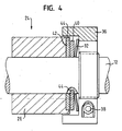
- FIG. 4 shows the friction assembly 24 in a second embodiment. Identical components are provided with the same reference numerals.
- the steering shaft housing 26 surrounds the steering shaft 12 partially and is made non-rotatable.
- the clamping nut 36 is fixed with the screws 38 on the steering shaft 12 and can rotate with the steering shaft 12.
- the spring 32 is supported on the clamping nut 36, and in this case presses a first friction disk 40 against a second friction disk 42.
- the first friction disc 40 is rotatably connected to the steering shaft 12 and the second friction disc 42 rotatably connected to the steering shaft housing 26.
Landscapes
- Engineering & Computer Science (AREA)
- General Engineering & Computer Science (AREA)
- Mechanical Engineering (AREA)
- Chemical & Material Sciences (AREA)
- Combustion & Propulsion (AREA)
- Transportation (AREA)
- Power Steering Mechanism (AREA)
- Steering Control In Accordance With Driving Conditions (AREA)
Claims (8)
- Ensemble comportant un volant de direction (10) et un générateur de résistance de direction (16) dans un système de direction par câble, dans lequel est prévu un ensemble de frottement (24) qui engendre un couple de frottement pour simuler un frottement mécanique d'un système de direction mécanique, dans lequel est prévu un ressort (32) qui est agencé entre l'ensemble de frottement (24) et un écrou de serrage (36), l'écrou de serrage (36) pouvant être fixé dans différentes positions sur un arbre de direction (12), et l'écrou de serrage étant monté sur l'arbre de direction (12) au moyen de vis (38).
- Ensemble selon la revendication 1, caractérisé en ce que l'ensemble de frottement (24) est relié à l'arbre de direction (12), l'ensemble de frottement (24) engendrant un couple de frottement lors d'un mouvement de rotation du volant de direction (10) et lors de la rotation de l'arbre de direction (12), qui en résulte.
- Ensemble selon la revendication 1 ou 2, caractérisé en ce qu'il est prévu un roulement à billes (28) qui est réalisé sous forme de roulement à billes à portée oblique.
- Ensemble selon la revendication 3, caractérisé en ce que le roulement à billes (28) est précontraint par le ressort (32).
- Ensemble selon la revendication 1 ou 2, caractérisé en ce qu'est agencée une première plaque de frottement (40) qui est précontrainte par le ressort (32).
- Ensemble selon la revendication 5, caractérisé en ce que la première plaque de frottement (40) est pressée par le ressort (32) contre une deuxième plaque de frottement (42).
- Ensemble selon la revendication 6, caractérisé en ce que la première plaque de frottement (40) est reliée de manière solidaire en rotation avec l'arbre de direction (12) et la deuxième plaque de frottement (42) est reliée de manière solidaire en rotation avec le boîtier d'arbre de direction (26).
- Ensemble selon la revendication 4 ou 5, caractérisé en ce que le ressort (42) est une rondelle Belleville.
Applications Claiming Priority (1)
| Application Number | Priority Date | Filing Date | Title |
|---|---|---|---|
| DE202004017030U DE202004017030U1 (de) | 2004-11-04 | 2004-11-04 | Baugruppe mit einem Lenkrad und einem Lenkwiderstandsgenerator |
Publications (3)
| Publication Number | Publication Date |
|---|---|
| EP1655202A2 EP1655202A2 (fr) | 2006-05-10 |
| EP1655202A3 EP1655202A3 (fr) | 2006-09-06 |
| EP1655202B1 true EP1655202B1 (fr) | 2009-04-29 |
Family
ID=34399984
Family Applications (1)
| Application Number | Title | Priority Date | Filing Date |
|---|---|---|---|
| EP05024145A Ceased EP1655202B1 (fr) | 2004-11-04 | 2005-11-04 | Ensemble avec volant et un générateur de résistance de la direction |
Country Status (2)
| Country | Link |
|---|---|
| EP (1) | EP1655202B1 (fr) |
| DE (2) | DE202004017030U1 (fr) |
Cited By (1)
| Publication number | Priority date | Publication date | Assignee | Title |
|---|---|---|---|---|
| US12509337B2 (en) | 2023-04-13 | 2025-12-30 | Crown Equipment Corporation | Steering shaft assembly for a materials handling vehicle |
Families Citing this family (5)
| Publication number | Priority date | Publication date | Assignee | Title |
|---|---|---|---|---|
| DE102012112361A1 (de) * | 2012-12-17 | 2014-06-18 | Zf Lenksysteme Gmbh | Lager für eine Lenkung eines Kraftfahrzeugs |
| DE102018205056A1 (de) | 2018-04-04 | 2019-10-10 | Thyssenkrupp Ag | Lenkvorrichtung mit simuliertem Lenkwiderstandsmoment |
| US20190308629A1 (en) * | 2018-04-06 | 2019-10-10 | GM Global Technology Operations LLC | Systems and methods for rough road detection |
| DE102019109886A1 (de) * | 2019-04-15 | 2020-10-15 | Schaeffler Technologies AG & Co. KG | Handkraftaktuator mit einem Sensorsystem zur Drehmomentdetektion |
| DE102020206435B4 (de) | 2020-05-25 | 2023-05-25 | Robert Bosch Gesellschaft mit beschränkter Haftung | Verfahren zur Beeinflussung einer Bewegung einer Lenkhandhabe eines Steer-by-Wire-Lenksystems in einem Fahrzeug |
Family Cites Families (6)
| Publication number | Priority date | Publication date | Assignee | Title |
|---|---|---|---|---|
| WO1986001168A1 (fr) * | 1984-08-09 | 1986-02-27 | Zahnradfabrik Friedrichshafen Ag | Mecanisme de direction a cremaillere, essentiellemnt pour vehicules a moteur |
| DE10057950A1 (de) * | 2000-11-22 | 2002-05-23 | Zf Lenksysteme Gmbh | Aktuator für Fahrzeuglenksysteme |
| US6678595B2 (en) * | 2002-03-29 | 2004-01-13 | Visteon Global Technologies, Inc. | System and method of simulating a steering resistance torque on a vehicle steering wheel |
| DE10221241A1 (de) * | 2002-05-13 | 2003-11-27 | Kostal Leopold Gmbh & Co Kg | Lenkeinrichtung für ein Kraftfahrzeug |
| DE10307567A1 (de) * | 2003-02-22 | 2004-09-02 | Linde Ag | Lenkvorrichtung mit einem eine Lenkkraft erzeugenden Lenkkraftsimulator |
| WO2004091995A2 (fr) * | 2003-04-08 | 2004-10-28 | Timken U.S. Coporation | Palier a friction a absence de jeu |
-
2004
- 2004-11-04 DE DE202004017030U patent/DE202004017030U1/de not_active Expired - Lifetime
-
2005
- 2005-11-04 EP EP05024145A patent/EP1655202B1/fr not_active Ceased
- 2005-11-04 DE DE502005007178T patent/DE502005007178D1/de not_active Expired - Lifetime
Cited By (1)
| Publication number | Priority date | Publication date | Assignee | Title |
|---|---|---|---|---|
| US12509337B2 (en) | 2023-04-13 | 2025-12-30 | Crown Equipment Corporation | Steering shaft assembly for a materials handling vehicle |
Also Published As
| Publication number | Publication date |
|---|---|
| EP1655202A2 (fr) | 2006-05-10 |
| EP1655202A3 (fr) | 2006-09-06 |
| DE502005007178D1 (de) | 2009-06-10 |
| DE202004017030U1 (de) | 2005-03-24 |
Similar Documents
| Publication | Publication Date | Title |
|---|---|---|
| EP1254824B1 (fr) | Dispositif de direction pour véhicule | |
| EP3615401B1 (fr) | Manette de direction | |
| EP3634832A1 (fr) | Colonne de direction pour véhicule automobile | |
| DE10157797A1 (de) | Simulatoreinheit für ein Lenkrad einer Fahrzeuglenkung | |
| DE102019202294A1 (de) | Lenkbegrenzungsvorrichtung, Steer-by-Wire-Lenksystem und Fahrzeug | |
| EP1268256A1 (fr) | Actionneur destine a un systeme de direction de vehicule | |
| DE102017211859A1 (de) | Multifunktionale Lenksäule, Kraftfahrzeug und Verfahren zum Betreiben eines Kraftfahrzeugs | |
| DE102019202293A1 (de) | Lenkvorrichtung, Steer-by-Wire-Lenksystem und Fahrzeug | |
| DE102020122695A1 (de) | Lenkvorrichtung für ein Kraftfahrzeug | |
| DE102018119977A1 (de) | Lenkgetriebe für ein Steer-by-Wire-Lenksystem | |
| DE10159330A1 (de) | Reaktionsmomentsimulator für ein Lenkrad einer Fahrzeuglenkung | |
| EP1655202B1 (fr) | Ensemble avec volant et un générateur de résistance de la direction | |
| DE102018130101A1 (de) | Feedback-Aktuator für eine Lenkeinrichtung mit Direktantrieb | |
| DE102018115565A1 (de) | Lenkradeinheit zur Erzeugung einer Rückmeldungskraft an einem Lenkrad für ein elektromechanisches Lenksystem | |
| DE19911892A1 (de) | Vorrichtung zur Lenkung eines Fahrzeugs | |
| DE102019103712B3 (de) | Feedback-Aktuator für eine Lenkeinrichtung mit Lenkwiderstandssystem | |
| DE102016000635A1 (de) | Lenksäule mit elektrischer Lenkungsverriegelung | |
| DE102019122903A1 (de) | Feedback-Aktuator | |
| DE102007053694B4 (de) | Fahrzeug-Lenksystem | |
| DE102019123514A1 (de) | Feedback-Aktuator für eine Lenkeinrichtung | |
| DE102023202122A1 (de) | Verfahren zum Betreiben eines Steer-by-Wire Lenksystems | |
| DE102023204740A1 (de) | Steer-by-wire-lenksäulenanordnung | |
| BE1029981B1 (de) | Lenksystem für ein Kraftfahrzeug | |
| DE102018120197A1 (de) | Lenkeinheit für eine Steer-by-wire-Lenkung eines Kraftfahrzeugs | |
| WO2004018277A1 (fr) | Direction de vehicule automobile comprenant une direction a superposition |
Legal Events
| Date | Code | Title | Description |
|---|---|---|---|
| PUAI | Public reference made under article 153(3) epc to a published international application that has entered the european phase |
Free format text: ORIGINAL CODE: 0009012 |
|
| AK | Designated contracting states |
Kind code of ref document: A2 Designated state(s): AT BE BG CH CY CZ DE DK EE ES FI FR GB GR HU IE IS IT LI LT LU LV MC NL PL PT RO SE SI SK TR |
|
| AX | Request for extension of the european patent |
Extension state: AL BA HR MK YU |
|
| PUAL | Search report despatched |
Free format text: ORIGINAL CODE: 0009013 |
|
| AK | Designated contracting states |
Kind code of ref document: A3 Designated state(s): AT BE BG CH CY CZ DE DK EE ES FI FR GB GR HU IE IS IT LI LT LU LV MC NL PL PT RO SE SI SK TR |
|
| AX | Request for extension of the european patent |
Extension state: AL BA HR MK YU |
|
| 17P | Request for examination filed |
Effective date: 20070226 |
|
| 17Q | First examination report despatched |
Effective date: 20070330 |
|
| AKX | Designation fees paid |
Designated state(s): AT BE |
|
| RBV | Designated contracting states (corrected) |
Designated state(s): DE FR |
|
| REG | Reference to a national code |
Ref country code: DE Ref legal event code: 8566 |
|
| GRAP | Despatch of communication of intention to grant a patent |
Free format text: ORIGINAL CODE: EPIDOSNIGR1 |
|
| GRAS | Grant fee paid |
Free format text: ORIGINAL CODE: EPIDOSNIGR3 |
|
| GRAA | (expected) grant |
Free format text: ORIGINAL CODE: 0009210 |
|
| AK | Designated contracting states |
Kind code of ref document: B1 Designated state(s): DE FR |
|
| REF | Corresponds to: |
Ref document number: 502005007178 Country of ref document: DE Date of ref document: 20090610 Kind code of ref document: P |
|
| PLBE | No opposition filed within time limit |
Free format text: ORIGINAL CODE: 0009261 |
|
| STAA | Information on the status of an ep patent application or granted ep patent |
Free format text: STATUS: NO OPPOSITION FILED WITHIN TIME LIMIT |
|
| 26N | No opposition filed |
Effective date: 20100201 |
|
| REG | Reference to a national code |
Ref country code: FR Ref legal event code: PLFP Year of fee payment: 11 |
|
| REG | Reference to a national code |
Ref country code: FR Ref legal event code: PLFP Year of fee payment: 12 |
|
| REG | Reference to a national code |
Ref country code: FR Ref legal event code: PLFP Year of fee payment: 13 |
|
| PGFP | Annual fee paid to national office [announced via postgrant information from national office to epo] |
Ref country code: FR Payment date: 20191125 Year of fee payment: 15 |
|
| PG25 | Lapsed in a contracting state [announced via postgrant information from national office to epo] |
Ref country code: FR Free format text: LAPSE BECAUSE OF NON-PAYMENT OF DUE FEES Effective date: 20201130 |
|
| PGFP | Annual fee paid to national office [announced via postgrant information from national office to epo] |
Ref country code: DE Payment date: 20220906 Year of fee payment: 18 |
|
| REG | Reference to a national code |
Ref country code: DE Ref legal event code: R119 Ref document number: 502005007178 Country of ref document: DE |
|
| PG25 | Lapsed in a contracting state [announced via postgrant information from national office to epo] |
Ref country code: DE Free format text: LAPSE BECAUSE OF NON-PAYMENT OF DUE FEES Effective date: 20240601 |
|
| PG25 | Lapsed in a contracting state [announced via postgrant information from national office to epo] |
Ref country code: DE Free format text: LAPSE BECAUSE OF NON-PAYMENT OF DUE FEES Effective date: 20240601 |