EP1655205B1 - System und Verfahren zur Lenkhilfe für die lenkbaren Räder eines Kraftfahrzeugs - Google Patents
System und Verfahren zur Lenkhilfe für die lenkbaren Räder eines Kraftfahrzeugs Download PDFInfo
- Publication number
- EP1655205B1 EP1655205B1 EP05300847A EP05300847A EP1655205B1 EP 1655205 B1 EP1655205 B1 EP 1655205B1 EP 05300847 A EP05300847 A EP 05300847A EP 05300847 A EP05300847 A EP 05300847A EP 1655205 B1 EP1655205 B1 EP 1655205B1
- Authority
- EP
- European Patent Office
- Prior art keywords
- steering
- wheels
- vehicle
- value
- assistance
- Prior art date
- Legal status (The legal status is an assumption and is not a legal conclusion. Google has not performed a legal analysis and makes no representation as to the accuracy of the status listed.)
- Expired - Lifetime
Links
Images

Classifications
-
- B—PERFORMING OPERATIONS; TRANSPORTING
- B62—LAND VEHICLES FOR TRAVELLING OTHERWISE THAN ON RAILS
- B62D—MOTOR VEHICLES; TRAILERS
- B62D6/00—Arrangements for automatically controlling steering depending on driving conditions sensed and responded to, e.g. control circuits
- B62D6/008—Control of feed-back to the steering input member, e.g. simulating road feel in steer-by-wire applications
Definitions
- the invention relates to a system and a method for assisting steering of the steering wheels of a motor vehicle.
- motor vehicles are provided with a chassis, a cabin, and wheels connected to the chassis by a suspension mechanism with front wheels steering controlled by a steering wheel available to the driver in the vehicle interior .
- a steering column secured to the steering wheel rotation whose lower end is provided with a pinion acting on a rack for rotating the wheels about a substantially vertical axis, in order to ensure their orientation and rotation of the vehicle chassis.
- Such steering mechanisms may be provided with a hydraulic or electrical assistance to reduce the efforts of the driver, especially when maneuvering at a standstill, for example a parking maneuver.
- Such mechanisms generally comprise a sensor for the angular position of the steering wheel mounted remotely from an actuator acting on the rack according to the angular position detected by the sensor to which it is connected by a wire link.
- the steering assistance systems of the steering wheels of a motor vehicle do not allow the driver to realize significantly a loss of grip of the vehicle wheels.
- the documents WO 03/099635 and EP 1508502 disclose a determination whether or not the estimated degree of adhesion is less than a predetermined value.
- the driver is warned that the estimated degree of adhesion of the front wheels of the vehicle is close to a limit.
- the warning to the driver can be done by increasing the power steering or steering assistance.
- a steering assistance system of the steering wheels of a motor vehicle comprising steering assisting means acting on turning means steering wheels, control means controlling the steering assistance means, and a device for determining information representative of the grip of the wheels of the steering wheel. vehicle.
- the system comprises assistance increasing means for increasing the steering assistance as soon as a value of the information representative of the grip of the wheels delivered by the determination device is less than a threshold value. characteristic of an adhesion limit of the wheels of the vehicle.
- Increasing the steering assistance when the wheel grip is less than a limit value causes a decrease in the torque exerted on the steering wheel and felt by the driver.
- the difference between the torque exerted on the steering wheel under driving conditions without loss of grip of the wheels, and the torque exerted on the steering wheel in driving conditions with loss of grip of the wheels can then easily be felt by the driver by the steering wheel.
- the system includes a speed sensor for providing a value of the vehicle speed.
- the assistance increasing means comprise modifying means capable of modifying a value of the speed of the vehicle, transmitted by the speed sensor to the control means and used to develop a steering assistance level, when the value of the information representative of the adhesion of the wheels, transmitted by the determining device, is less than the threshold value.
- the increase in steering assistance of the steering wheels is performed by modifying the value of the speed of the vehicle transmitted to the control means, when a loss of adhesion of the wheels of the vehicle is detected.
- the control means control the steering assistance means in particular depending on the value of the speed of the vehicle.
- the modifying means are adapted to reduce a value of the speed of the vehicle transmitted by the speed sensor, when the determining device transmits a value of the information representative of the adhesion of the lower wheels to the threshold value.
- the change in the value of the vehicle speed transmitted to the control means making it possible to obtain an increase in steering assistance of the steering wheels is a reduction in the value of the speed of the vehicle delivered by the speed sensor.
- the strategies of the power steering controls is to decrease the assistance when the speed of the vehicle increases. Indeed, the higher the speed, the less important the assistance to the direction, to decrease the risks of accident.
- the system further comprises a flywheel secured to a rotation of a steering column, and a torque sensor and an angle sensor mounted behind the steering wheel on the steering column.
- the control means are adapted to control the steer steering assistance means from operating parameters of the vehicle comprising a torque exerted on the steering wheel and transmitted by the torque sensor, an angular position of the steering wheel transmitted by the sensor. angle, and a speed, modified or not, transmitted by the modifying means.
- the steering wheel steering assistance means are electrical or hydraulic means.
- a method of assisting steering of the steering wheels of a motor vehicle in which the steering assistance is increased as soon as the value of information representative of the Wheel adhesion is less than a threshold value characteristic of a wheel grip limit of the vehicle.
- the steering assistance is increased by modifying a value of the vehicle speed used to develop a steering assistance level, when the value of the information representative of the grip of the wheels is less than the threshold value.
- the steering assistance is increased by decreasing the value of the vehicle speed, when the value of the information representative of the adhesion of the wheels is less than the threshold value.
- steering assistance of the steering wheels is controlled from operating parameters of the vehicle comprising a torque exerted on the steering wheel, an angular position of the steering wheel, and the modified or unmodified speed of the vehicle.
- the vehicle comprises two steering wheels 1 and 2.
- the vehicle is equipped with a steering wheel 3 secured to a rotation of a steering column 4 connected to a rack 5 which converts a rotational movement steering wheel 3 in a translational movement.
- the transmission of a translation movement of the rack 5 towards the two steering wheels 1 and 2 is ensured by links 6 and 7 respectively, which transform a translation movement of the rack 5 into a rotational movement of the steering wheels 1 and 2.
- a steering assistance module 8 for the steering wheels 1 and 2 generates an assistance effort on the steering column 4 via a gearbox 9.
- the assistance module 8 is connected to the gearbox 9 by a shaft 10.
- This assistance module 8 may for example be an electric motor or a hydraulic device.
- a control unit 11 managing various devices on board the vehicle includes a control module 12 which controls the steering assistance module 8 steering wheels 1 and 2.
- a torque sensor 13 and an angle sensor 14 are mounted on the steering column 4, just behind the steering wheel 3.
- the torque sensor 13 transmits to the control module 12 a torque C flying exerted on the steering wheel 3, it is that is to say on the steering column 4 which is integral in rotation with the steering wheel 3, via a connection 15.
- the angle sensor 14 transmits to the control module 12 an angular position of the steering wheel ⁇ vol relative to a defined reference position, via a connection 16.
- the control unit 11 also comprises a module 17 for increasing steering assistance of the steering wheels 1 and 2.
- the assistance increasing module 17 comprises a modification module 18.
- a speed sensor 19 outputs, through a connection 20, a measured speed v mes of the vehicle, to the modification module 18.
- a determining device 21 outputs, via a connection 22, information ⁇ representative of the adhesion of the wheels of the vehicle to the modification module 18.
- Such a device 21 for determining information ⁇ representative of the adhesion of the wheels of the vehicle is for example provided by systems such as an ABS braking system.
- the control module 12 controls the steering assistance module 8 of the steering wheels 1 and 2, via a connection 23.
- the modification module 18 When the value of the information ⁇ representative of the adhesion of the wheels of the vehicle is less than a threshold value characteristic of a limit of adhesion of the wheels of the vehicle, the modification module 18 will transmit to the control module 12 a speed value v mod modified. More precisely, the speed value v mod transmitted to the control module 12 is less than the actual speed measured v mes of the vehicle. The speed v mod is transmitted from the modification module 18 to the control module 12 via a connection 24.
- the known control modules operate in such a way as to reduce steering assistance of the steering wheels 1 and 2 as the speed increases, decreasing the value of the speed transmitted to the control module 12 causes an increase in the steering wheel steering assistance. 1 and 2.
- the modification module 18 modifies, during a step 32 , the value of the speed measured v mes in a speed value v mod transmitted to the control module 12.
- the modified value of the speed v mod is then lower than the speed measured v mes of the vehicle, so that the control module 12 increases steering assistance of the steering wheels 1 and 2 during a step 33.
- the modification module 18 does not modify the value of the measured speed v mes , and transmits to the control module a value of the modified speed v mod equal to the speed measured v mes of the vehicle, during a step 34.
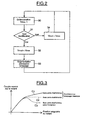
- FIG. 3 is a set of curves C 1 , C 2 and C 3 , representing the torque exerted on the steering wheel 3, as a function of the angular position of the steering wheel.
- the curve C 1 is representative of a conventional steering assistance in a driving situation without loss of adhesion.
- the curve C 2 is representative of a conventional steering assistance in a driving situation with loss of grip.
- curve C 3 is representative of a steering assistance, with loss of adhesion, according to the invention.
- the three curves are combined for values of low angular positions of the steering wheel.
- the curve C 1 is then greater than the curve C 2 , itself greater than the curve C 3 , for such values of higher angular positions.
- the difference between the curves C 1 and C 2 represents the variation of the torque exerted on the steering wheel 3, between a driving without loss of traction of the wheels, and a driving with loss of traction of the wheels, for assistance systems turning steering wheels 1 and 2, or power steering. This difference in torque is low, and does not allow the driver to feel, through the torque exerted on the steering wheel, a loss of grip of the vehicle wheels.
- the invention allows the driver to realize a loss of adhesion of the wheels of the vehicle, as shown by the curve C 3 .
- steering assistance steered wheels is increased, which significantly reduces the torque exerted on the steering wheel.
- the difference between the torque exerted on the steering wheel, felt by the driver, without loss of grip of the wheels and with loss of grip of the wheels, represented by the difference between the curves C 1 and C 3 is then significantly increased, by ratio to the difference between the curves C 1 and C 2 illustrating conventional steering assistance systems.
- the invention therefore makes it possible to have a system for assisting steering of the steering wheels of a motor vehicle, which does not attenuate the difference in torque exerted on the steering wheel between a driving without loss of grip and a driving with loss. adhesion. The driver can then easily feel a loss of grip of the vehicle, and thus take into account.
Landscapes
- Engineering & Computer Science (AREA)
- Chemical & Material Sciences (AREA)
- Combustion & Propulsion (AREA)
- Transportation (AREA)
- Mechanical Engineering (AREA)
- Steering Control In Accordance With Driving Conditions (AREA)
- Power Steering Mechanism (AREA)
Claims (7)
- System zur Lenkhilfe für die lenkbaren Räder (1, 2) eines Kraftfahrzeugs, umfassend Lenkhilfsmittel (8), die auf die Lenkmittel (5, 7) der lenkbaren Räder (1, 2) wirken, Steuermittel (12), die die Lenkhilfsmittel (8) steuern, und eine Vorrichtung (21) zur Bestimmung einer die Haftung der Fahrzeugräder darstellenden Information (τ), wobei das System ferner Hilfsverstärkungsmittel (17) umfasst, um die Lenkhilfe zu verstärken, wenn ein die Radhaftung darstellender Informationswert (τ), der von der Bestimmungsvorrichtung (21) geliefert wird, unterhalb eines Schwellwerts liegt, welcher einen Haftungsgrenzwert der Fahrzeugräder kennzeichnet, dadurch gekennzeichnet, dass es einen Geschwindigkeitssensor (19) umfasst, um einen Wert (vmes) der Fahrzeuggeschwindigkeit zu liefern, und dass die Hilfsverstärkungsmittel (17) Modifikationsmittel (18) umfassen, die in der Lage sind, den Wert (vmes) der Fahrzeuggeschwindigkeit zu modifizieren, welcher von dem Geschwindigkeitssensor (19) zu den Steuermitteln (12) gesendet und zur Erstellung eines Lenkhilfsniveaus verwendet wird, wenn der die Radhaftung darstellende Informationswert (τ), welcher von der Bestimmungsvorrichtung (21) gesendet wird, unter dem Schwellwert liegt.
- System nach Anspruch 1, dadurch gekennzeichnet, dass die Modifikationsmittel (18) dazu ausgelegt sind, einen Wert (vmes) der Fahrzeuggeschwindigkeit, welcher von dem Geschwindigkeitssensor (19) gesendet wird, zu verringern, wenn die Bestimmungsvorrichtung (21) einen die Radhaftung darstellenden Informationswert (τ) sendet, welcher unter dem Schwellwert liegt.
- System nach Anspruch 1 oder 2, dadurch gekennzeichnet, dass das System ferner ein Lenkrad (3), welches sich mit einer Lenksäule (4) dreht, und einen Drehmomentsensor (13) und einen Winkelsensor (14), welche hinter dem Lenkrad (3) an der Lenksäule (4) angebracht sind, umfasst, und dadurch, dass die Steuermittel (12) dazu ausgelegt sind, die Lenkhilfsmittel (8) der lenkbaren Räder (1, 2) ausgehend von Funktionsparametern des Fahrzeugs zu steuern, welche ein auf das Lenkrad ausgeübtes und von dem Drehmomentsensor gesendetes Drehmoment (Cvol), eine von dem Winkelsensor (14) gesendete Winkelposition des Lenkrads (αvol) und eine gegebenenfalls modifizierte, von den Modifikationsmitteln (18) gesendete Geschwindigkeit (Vmod) umfassen.
- System nach einem der Ansprüche 1 bis 3, dadurch gekennzeichnet, dass es sich bei den Lenkhilfsmitteln (8) der lenkbaren Räder um elektrische oder hydraulische Mittel handelt.
- Verfahren zur Lenkhilfe für die lenkbaren Räder (1, 2) eines Kraftfahrzeugs, bei dem die Lenkhilfe verstärkt wird, wenn der Wert einer die Radhaftung darstellenden Information (τ) unter einem Schwellwert liegt, welcher die Haftungsgrenze der Fahrzeugräder kennzeichnet, dadurch gekennzeichnet, dass die Lenkhilfe verstärkt wird, indem ein Wert (vmes) der Fahrzeuggeschwindigkeit modifiziert wird, welcher zum Erstellen eines Lenkhilfeniveaus verwendet wird, wenn der die Radhaftung darstellende Informationswert (τ) unter dem Schwellwert liegt.
- Verfahren nach Anspruch 5, dadurch gekennzeichnet, dass die Lenkhilfe verstärkt wird, indem der Wert (Vmes) der Fahrzeuggeschwindigkeit verringert wird, wenn der die Radhaftung darstellende Informationswert (τ) unter dem Schwellwert liegt.
- Verfahren nach Anspruch 5 oder 6, dadurch gekennzeichnet, dass die Lenkhilfe der lenkbaren Räder (1, 2) ausgehend von Funktionsparametern des Fahrzeugs gesteuert wird, welche ein auf das Lenkrad ausgeübtes Drehmoment (Cvol), eine Winkelposition des Lenkrads (αvol) und die gegebenenfalls modifizierte Geschwindigkeit (vmod) des Fahrzeugs umfassen.
Applications Claiming Priority (1)
| Application Number | Priority Date | Filing Date | Title |
|---|---|---|---|
| FR0411937A FR2877631B1 (fr) | 2004-11-09 | 2004-11-09 | Systeme et procede d'assistance au braquage des roues directrices d'un vehicule automobile |
Publications (2)
| Publication Number | Publication Date |
|---|---|
| EP1655205A1 EP1655205A1 (de) | 2006-05-10 |
| EP1655205B1 true EP1655205B1 (de) | 2007-09-19 |
Family
ID=34951490
Family Applications (1)
| Application Number | Title | Priority Date | Filing Date |
|---|---|---|---|
| EP05300847A Expired - Lifetime EP1655205B1 (de) | 2004-11-09 | 2005-10-24 | System und Verfahren zur Lenkhilfe für die lenkbaren Räder eines Kraftfahrzeugs |
Country Status (4)
| Country | Link |
|---|---|
| EP (1) | EP1655205B1 (de) |
| AT (1) | ATE373595T1 (de) |
| DE (1) | DE602005002521T2 (de) |
| FR (1) | FR2877631B1 (de) |
Families Citing this family (1)
| Publication number | Priority date | Publication date | Assignee | Title |
|---|---|---|---|---|
| DE102009026997A1 (de) * | 2009-06-17 | 2011-04-07 | Robert Bosch Gmbh | Verfahren zur Lenkmomentbeeinflussung in einem Fahrzeuglenksystem |
Family Cites Families (4)
| Publication number | Priority date | Publication date | Assignee | Title |
|---|---|---|---|---|
| US4527653A (en) | 1984-01-23 | 1985-07-09 | General Motors Corporation | Road load insensitive electric power steering system |
| JP3525969B2 (ja) | 1995-12-01 | 2004-05-10 | 本田技研工業株式会社 | 電動パワーステアリング装置 |
| US6062336A (en) | 1998-11-13 | 2000-05-16 | General Motors Corporation | Adaptive variable effort power steering system |
| JP3970095B2 (ja) * | 2002-05-27 | 2007-09-05 | 株式会社ジェイテクト | 操舵装置 |
-
2004
- 2004-11-09 FR FR0411937A patent/FR2877631B1/fr not_active Expired - Fee Related
-
2005
- 2005-10-24 DE DE602005002521T patent/DE602005002521T2/de not_active Expired - Lifetime
- 2005-10-24 AT AT05300847T patent/ATE373595T1/de not_active IP Right Cessation
- 2005-10-24 EP EP05300847A patent/EP1655205B1/de not_active Expired - Lifetime
Also Published As
| Publication number | Publication date |
|---|---|
| EP1655205A1 (de) | 2006-05-10 |
| DE602005002521T2 (de) | 2008-06-12 |
| ATE373595T1 (de) | 2007-10-15 |
| FR2877631B1 (fr) | 2008-06-06 |
| DE602005002521D1 (de) | 2007-10-31 |
| FR2877631A1 (fr) | 2006-05-12 |
Similar Documents
| Publication | Publication Date | Title |
|---|---|---|
| EP2018308B1 (de) | Elektrisches servolenksystem für ein kraftfahrzeug | |
| EP2373529B1 (de) | Verfahren zur bestimmung des untersteuerungsgrads eines fahrzeugs mit servolenkung und zur optimalen korrektur der servolenkung | |
| FR2660258A1 (fr) | Vehicule electrique a vitesse reglable en toute securite. | |
| FR2712548A1 (fr) | Moyen d'assistance aux manÓoeuvres de garage avec action des freins. | |
| FR2892086A1 (fr) | Systeme d'aide a la manoeuvre pour un vehicule automobile. | |
| EP2181031B1 (de) | Servolenkvorrichtung für automobile | |
| EP1848625B1 (de) | Verfahren zur masskorrektur des auf ein elektronisch gestütztes lenkrad eines kraftfahrzeugs ausgeübten drehmoments | |
| EP1655205B1 (de) | System und Verfahren zur Lenkhilfe für die lenkbaren Räder eines Kraftfahrzeugs | |
| EP1574417B1 (de) | Elektrische Servolenkeinrichtung für ein Kraftfahrzeug, Lenkanordnung mit einer solchen Servolenkeinrichtung und mit einer solchen Lenkanordnung ausgerüstetes Kraftfahrzeug | |
| FR3117986A1 (fr) | Procede d’aide au reglage de parallelisme d’un train avant d’un vehicule automobile | |
| EP1935739B1 (de) | Verfahren zu Automatisierung des Lenkeinschlags der Reifen eines Kraftfahrzeugs zum Ausparken des Fahrzeugs aus einem Parkplatz und entsprechendes System | |
| FR2914260A1 (fr) | Vehicule motorise comprenant une unite de controle du vehicule se trouvant en situation de virage et procede correspondant. | |
| FR3144963A1 (fr) | ensemble de direction pour véhicule automobile | |
| FR2916721A1 (fr) | Vehicule motorise a quatre roues comportant deux roues arrieres directrices. | |
| EP1713680B1 (de) | Verfahren und system zur unterstützung der lenkung von gelenkten rädern eines so ausgestatteten fahrzeugs | |
| FR2846645A1 (fr) | Procede et dispositif de guidage d'un chariot de manutention | |
| FR2851219A1 (fr) | Procede de reduction du diametre de braquage d'un vehicule automobile et vehicule automobile | |
| EP0401095B1 (de) | Verfahren und Vorrichtung zur Steuerung eines Differentials, insbesondere für ein Kraftfahrzeug | |
| FR2861043A1 (fr) | Vehicule automobile a stabilite amelioree en cas de freinage dissymetrique et methode de freinage associee. | |
| FR2965782A1 (fr) | Procede de gestion de l'angle de braquage d'un vehicule | |
| EP1738991B1 (de) | System und Verfahren zur Ansteueren des Einschlagens der Hinterräder eines Fahrzeuges mit Vierradlenkung | |
| FR2887842A1 (fr) | Systeme d'aide a la manoeuvre d'un vehicule automobile | |
| FR3153323A1 (fr) | Procédé de commande automatique de direction électrique d’un véhicule automobile | |
| EP1029772A1 (de) | Regelungsverfahren- und Vorrichtung für das auf die Kraftfahrzeuglenkvorrichtung aufgebrachte Hilfsmoment | |
| FR3158282A1 (fr) | Unité de contrôle électronique pour système de commande de freinage |
Legal Events
| Date | Code | Title | Description |
|---|---|---|---|
| PUAI | Public reference made under article 153(3) epc to a published international application that has entered the european phase |
Free format text: ORIGINAL CODE: 0009012 |
|
| AK | Designated contracting states |
Kind code of ref document: A1 Designated state(s): AT BE BG CH CY CZ DE DK EE ES FI FR GB GR HU IE IS IT LI LT LU LV MC NL PL PT RO SE SI SK TR |
|
| AX | Request for extension of the european patent |
Extension state: AL BA HR MK YU |
|
| 17P | Request for examination filed |
Effective date: 20060620 |
|
| 17Q | First examination report despatched |
Effective date: 20060814 |
|
| AKX | Designation fees paid |
Designated state(s): AT BE BG CH CY CZ DE DK EE ES FI FR GB GR HU IE IS IT LI LT LU LV MC NL PL PT RO SE SI SK TR |
|
| GRAP | Despatch of communication of intention to grant a patent |
Free format text: ORIGINAL CODE: EPIDOSNIGR1 |
|
| GRAS | Grant fee paid |
Free format text: ORIGINAL CODE: EPIDOSNIGR3 |
|
| GRAA | (expected) grant |
Free format text: ORIGINAL CODE: 0009210 |
|
| AK | Designated contracting states |
Kind code of ref document: B1 Designated state(s): AT BE BG CH CY CZ DE DK EE ES FI FR GB GR HU IE IS IT LI LT LU LV MC NL PL PT RO SE SI SK TR |
|
| REG | Reference to a national code |
Ref country code: GB Ref legal event code: FG4D Free format text: NOT ENGLISH |
|
| REG | Reference to a national code |
Ref country code: CH Ref legal event code: EP |
|
| REF | Corresponds to: |
Ref document number: 602005002521 Country of ref document: DE Date of ref document: 20071031 Kind code of ref document: P |
|
| REG | Reference to a national code |
Ref country code: IE Ref legal event code: FG4D Free format text: LANGUAGE OF EP DOCUMENT: FRENCH |
|
| PG25 | Lapsed in a contracting state [announced via postgrant information from national office to epo] |
Ref country code: FI Free format text: LAPSE BECAUSE OF FAILURE TO SUBMIT A TRANSLATION OF THE DESCRIPTION OR TO PAY THE FEE WITHIN THE PRESCRIBED TIME-LIMIT Effective date: 20070919 Ref country code: LT Free format text: LAPSE BECAUSE OF FAILURE TO SUBMIT A TRANSLATION OF THE DESCRIPTION OR TO PAY THE FEE WITHIN THE PRESCRIBED TIME-LIMIT Effective date: 20070919 |
|
| PG25 | Lapsed in a contracting state [announced via postgrant information from national office to epo] |
Ref country code: AT Free format text: LAPSE BECAUSE OF FAILURE TO SUBMIT A TRANSLATION OF THE DESCRIPTION OR TO PAY THE FEE WITHIN THE PRESCRIBED TIME-LIMIT Effective date: 20070919 Ref country code: PL Free format text: LAPSE BECAUSE OF FAILURE TO SUBMIT A TRANSLATION OF THE DESCRIPTION OR TO PAY THE FEE WITHIN THE PRESCRIBED TIME-LIMIT Effective date: 20070919 |
|
| NLV1 | Nl: lapsed or annulled due to failure to fulfill the requirements of art. 29p and 29m of the patents act | ||
| PG25 | Lapsed in a contracting state [announced via postgrant information from national office to epo] |
Ref country code: LV Free format text: LAPSE BECAUSE OF FAILURE TO SUBMIT A TRANSLATION OF THE DESCRIPTION OR TO PAY THE FEE WITHIN THE PRESCRIBED TIME-LIMIT Effective date: 20070919 |
|
| BERE | Be: lapsed |
Owner name: RENAULT S.A.S. Effective date: 20071031 |
|
| PG25 | Lapsed in a contracting state [announced via postgrant information from national office to epo] |
Ref country code: ES Free format text: LAPSE BECAUSE OF FAILURE TO SUBMIT A TRANSLATION OF THE DESCRIPTION OR TO PAY THE FEE WITHIN THE PRESCRIBED TIME-LIMIT Effective date: 20071230 Ref country code: GR Free format text: LAPSE BECAUSE OF FAILURE TO SUBMIT A TRANSLATION OF THE DESCRIPTION OR TO PAY THE FEE WITHIN THE PRESCRIBED TIME-LIMIT Effective date: 20071220 Ref country code: NL Free format text: LAPSE BECAUSE OF FAILURE TO SUBMIT A TRANSLATION OF THE DESCRIPTION OR TO PAY THE FEE WITHIN THE PRESCRIBED TIME-LIMIT Effective date: 20070919 |
|
| REG | Reference to a national code |
Ref country code: IE Ref legal event code: FD4D |
|
| PG25 | Lapsed in a contracting state [announced via postgrant information from national office to epo] |
Ref country code: SK Free format text: LAPSE BECAUSE OF FAILURE TO SUBMIT A TRANSLATION OF THE DESCRIPTION OR TO PAY THE FEE WITHIN THE PRESCRIBED TIME-LIMIT Effective date: 20070919 Ref country code: PT Free format text: LAPSE BECAUSE OF FAILURE TO SUBMIT A TRANSLATION OF THE DESCRIPTION OR TO PAY THE FEE WITHIN THE PRESCRIBED TIME-LIMIT Effective date: 20080219 Ref country code: CZ Free format text: LAPSE BECAUSE OF FAILURE TO SUBMIT A TRANSLATION OF THE DESCRIPTION OR TO PAY THE FEE WITHIN THE PRESCRIBED TIME-LIMIT Effective date: 20070919 Ref country code: GB Free format text: LAPSE BECAUSE OF FAILURE TO SUBMIT A TRANSLATION OF THE DESCRIPTION OR TO PAY THE FEE WITHIN THE PRESCRIBED TIME-LIMIT Effective date: 20070919 Ref country code: MC Free format text: LAPSE BECAUSE OF NON-PAYMENT OF DUE FEES Effective date: 20071031 Ref country code: IS Free format text: LAPSE BECAUSE OF FAILURE TO SUBMIT A TRANSLATION OF THE DESCRIPTION OR TO PAY THE FEE WITHIN THE PRESCRIBED TIME-LIMIT Effective date: 20080119 |
|
| PG25 | Lapsed in a contracting state [announced via postgrant information from national office to epo] |
Ref country code: SE Free format text: LAPSE BECAUSE OF FAILURE TO SUBMIT A TRANSLATION OF THE DESCRIPTION OR TO PAY THE FEE WITHIN THE PRESCRIBED TIME-LIMIT Effective date: 20071219 Ref country code: RO Free format text: LAPSE BECAUSE OF FAILURE TO SUBMIT A TRANSLATION OF THE DESCRIPTION OR TO PAY THE FEE WITHIN THE PRESCRIBED TIME-LIMIT Effective date: 20070919 |
|
| PLBE | No opposition filed within time limit |
Free format text: ORIGINAL CODE: 0009261 |
|
| STAA | Information on the status of an ep patent application or granted ep patent |
Free format text: STATUS: NO OPPOSITION FILED WITHIN TIME LIMIT |
|
| PG25 | Lapsed in a contracting state [announced via postgrant information from national office to epo] |
Ref country code: DK Free format text: LAPSE BECAUSE OF FAILURE TO SUBMIT A TRANSLATION OF THE DESCRIPTION OR TO PAY THE FEE WITHIN THE PRESCRIBED TIME-LIMIT Effective date: 20070919 |
|
| 26N | No opposition filed |
Effective date: 20080620 |
|
| PG25 | Lapsed in a contracting state [announced via postgrant information from national office to epo] |
Ref country code: BE Free format text: LAPSE BECAUSE OF NON-PAYMENT OF DUE FEES Effective date: 20071031 |
|
| PG25 | Lapsed in a contracting state [announced via postgrant information from national office to epo] |
Ref country code: IE Free format text: LAPSE BECAUSE OF FAILURE TO SUBMIT A TRANSLATION OF THE DESCRIPTION OR TO PAY THE FEE WITHIN THE PRESCRIBED TIME-LIMIT Effective date: 20070919 |
|
| REG | Reference to a national code |
Ref country code: FR Ref legal event code: ST Effective date: 20081020 |
|
| PG25 | Lapsed in a contracting state [announced via postgrant information from national office to epo] |
Ref country code: EE Free format text: LAPSE BECAUSE OF FAILURE TO SUBMIT A TRANSLATION OF THE DESCRIPTION OR TO PAY THE FEE WITHIN THE PRESCRIBED TIME-LIMIT Effective date: 20070919 |
|
| PG25 | Lapsed in a contracting state [announced via postgrant information from national office to epo] |
Ref country code: FR Free format text: LAPSE BECAUSE OF NON-PAYMENT OF DUE FEES Effective date: 20071031 |
|
| PG25 | Lapsed in a contracting state [announced via postgrant information from national office to epo] |
Ref country code: SI Free format text: LAPSE BECAUSE OF FAILURE TO SUBMIT A TRANSLATION OF THE DESCRIPTION OR TO PAY THE FEE WITHIN THE PRESCRIBED TIME-LIMIT Effective date: 20070919 |
|
| PG25 | Lapsed in a contracting state [announced via postgrant information from national office to epo] |
Ref country code: CY Free format text: LAPSE BECAUSE OF FAILURE TO SUBMIT A TRANSLATION OF THE DESCRIPTION OR TO PAY THE FEE WITHIN THE PRESCRIBED TIME-LIMIT Effective date: 20070919 |
|
| PG25 | Lapsed in a contracting state [announced via postgrant information from national office to epo] |
Ref country code: LU Free format text: LAPSE BECAUSE OF NON-PAYMENT OF DUE FEES Effective date: 20071024 Ref country code: BG Free format text: LAPSE BECAUSE OF FAILURE TO SUBMIT A TRANSLATION OF THE DESCRIPTION OR TO PAY THE FEE WITHIN THE PRESCRIBED TIME-LIMIT Effective date: 20071219 |
|
| PG25 | Lapsed in a contracting state [announced via postgrant information from national office to epo] |
Ref country code: TR Free format text: LAPSE BECAUSE OF FAILURE TO SUBMIT A TRANSLATION OF THE DESCRIPTION OR TO PAY THE FEE WITHIN THE PRESCRIBED TIME-LIMIT Effective date: 20070919 Ref country code: HU Free format text: LAPSE BECAUSE OF FAILURE TO SUBMIT A TRANSLATION OF THE DESCRIPTION OR TO PAY THE FEE WITHIN THE PRESCRIBED TIME-LIMIT Effective date: 20080320 |
|
| REG | Reference to a national code |
Ref country code: CH Ref legal event code: PL |
|
| PG25 | Lapsed in a contracting state [announced via postgrant information from national office to epo] |
Ref country code: CH Free format text: LAPSE BECAUSE OF NON-PAYMENT OF DUE FEES Effective date: 20091031 Ref country code: LI Free format text: LAPSE BECAUSE OF NON-PAYMENT OF DUE FEES Effective date: 20091031 |
|
| PG25 | Lapsed in a contracting state [announced via postgrant information from national office to epo] |
Ref country code: IT Free format text: LAPSE BECAUSE OF NON-PAYMENT OF DUE FEES Effective date: 20071031 |
|
| PGFP | Annual fee paid to national office [announced via postgrant information from national office to epo] |
Ref country code: DE Payment date: 20171019 Year of fee payment: 13 |
|
| REG | Reference to a national code |
Ref country code: DE Ref legal event code: R119 Ref document number: 602005002521 Country of ref document: DE |
|
| PG25 | Lapsed in a contracting state [announced via postgrant information from national office to epo] |
Ref country code: DE Free format text: LAPSE BECAUSE OF NON-PAYMENT OF DUE FEES Effective date: 20190501 |