EP1655261B1 - Wind deflector for cranes and crane provided with said wind deflector - Google Patents
Wind deflector for cranes and crane provided with said wind deflector Download PDFInfo
- Publication number
- EP1655261B1 EP1655261B1 EP20050109360 EP05109360A EP1655261B1 EP 1655261 B1 EP1655261 B1 EP 1655261B1 EP 20050109360 EP20050109360 EP 20050109360 EP 05109360 A EP05109360 A EP 05109360A EP 1655261 B1 EP1655261 B1 EP 1655261B1
- Authority
- EP
- European Patent Office
- Prior art keywords
- deflector
- windbreaker
- counterjib
- crane
- crane according
- Prior art date
- Legal status (The legal status is an assumption and is not a legal conclusion. Google has not performed a legal analysis and makes no representation as to the accuracy of the status listed.)
- Expired - Lifetime
Links
Images

Classifications
-
- B—PERFORMING OPERATIONS; TRANSPORTING
- B66—HOISTING; LIFTING; HAULING
- B66C—CRANES; LOAD-ENGAGING ELEMENTS OR DEVICES FOR CRANES, CAPSTANS, WINCHES, OR TACKLES
- B66C23/00—Cranes comprising essentially a beam, boom, or triangular structure acting as a cantilever and mounted for translatory of swinging movements in vertical or horizontal planes or a combination of such movements, e.g. jib-cranes, derricks, tower cranes
- B66C23/62—Constructional features or details
- B66C23/72—Counterweights or supports for balancing lifting couples
Definitions
- the present invention concerns a revolving crane.
- the present invention relates to revolving cranes with upper counterpoise.
- Such known cranes comprise, for instance, cranes referred to as “tower crane” or “city crane”, or “counterjib crane”. They consist of a vertical tower that is anchored to the ground, in fixed or displaceable position, by means of a ballasted base or of other -even non-displaceable- fastenings; said base supports a lift jib and a counterjib, either directly or through a connection structure.
- the lift jib and the counterjib can be rotatably connected to a fixed vertical tower; alternatively, the lift jib and the counterjib can be connected in fixed way to a vertical tower that can rotate around its axis.
- ballast in general consists of a plurality of blocks of material having a high specific weight, such as concrete, cast iron, steel, etc
- DE 3345327 discloses a tower crane comprising a counter-jib equipped with a lateral wind shield which can assume a first position parallel to the crane axis in the working state and perpendicular to the crane axis in the rest state.
- GB 742,368 discloses a jib crane equipped with a mast having tubular members in which a cabin for crane control can be provided, said tubular members being provided with external surface arranged to give reduced wind resistance.
- operating wind the wind is meant that acts on the crane during operation; during operation, the wind strikes the crane in zones that vary depending on the crane position relative to the wind direction, that is sometimes on the sides, sometimes on the front, sometimes on the rear part.
- non-operating wind the maximum wind is meant that strikes the crane when the latter is not operating, that is at rest; in “non-operating wind” conditions, the crane rotates around its rotation axis due to the only thrust of the wind and, consequently, tends to align itself in the wind direction, so as to be struck on the back and to provide the last possible resistance. In this condition the wind strikes the rear wall of the free end of the counterjib, that it is usually made up of an assembly of surfaces substantially perpendicular both to the ground and to the lift jib.
- the present invention originates and can be applied expecially to improving the safety and the stability of a crane of the kind previously described when its structure must resist to the condition of "non-operating wind” (or “storm wind”).
- an object of the present invention is to provide a device that concurs to increase the crane safety and stability in "non-operating wind-” or “storm wind” conditions, without substantially modifying or interfering with the structure or operation of the crane itself.
- the increase of the stability and resistance to the "non-operating wind" of a crane with upper counterpoise is achieved by installing a windbreaker deflector according to the present invention at the free end of the counterjib of said crane.
- the windbreaker deflector according to the invention allows diverting the air flow that otherwise would strike the rear wall of the free end of the counterjib and of the counterpoise or ballast. Therefore, thanks to the action of said windbreaker deflector, the shape coefficient -defined for instance in the above quoted calculation norm FEM 1.004-is greatly reduced, that has to be considered for calculating the wind pressure on the part of counterpoise struck by the wind itself.
- the counterjib provides a minimum resistance to the wind.
- the windbreaker deflector has a rounded profile and has preferably a semicircular section: such profile on one hand allows to reduce the resistance to the wind that strikes the deflector and, on the following detailed description, with reference to the attached Figures, wherein:
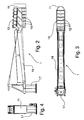
- the counterjib is shown of a traditional upper counterpoise crane; said counterjib 1 comprises a pair of lateral bulkheads 13, arranged for containing a counterpoise or ballast 15 made up of a plurality of blocks placed side by side each to another, and also made up of a beam or horizontal frame 19, which in its turn is fixed to a revolving structure 17; said structure 17 allows the lift jib (not shown) and the counterjib 1 to be rotated relative to the vertical tower (not shown).
- a windbreaker deflector 11 is fixed on the counterjib 1, at the free end of said counterjib.
- Said windbreaker deflector 11 has the purpose of "breaking" the wind that, otherwise, would directly strike the counterpoise or ballast 15 of said counterjib 1, in particular in conditions in which the crane is not operating.
- the crane due to the wind action, rotates so as to align itself along the direction of the wind itself: in such conditions, the presence of said windbreaker deflector 11 arranged at the free end of the counterjib 1 concurs “to cut” the wind and to expose the minimum possible resistance to the wind itself, allowed by the crane structure.
- windbreaker deflector 11 has advantageously a rounded, substantially semi-cylindrical shape, with the concavity directed towards the counterjib 1, since such shape contributes to reduce the resistance to the wind and, at the same time, allows the overall dimensions of said deflector to be kept limited.
- any rounded shape profile can advantageously be used for the windbreaker deflector 11; for instance, rather than having a semi-cylindrical shape with circular section, as shown in Figure 3 , the deflector 11 can have a semi-cylindrical shape with elliptic section or also a semispherical or semiellissoidal shape.
- the rounded profile of windbreaker deflector 11 can be approximated with a body having a prismatic shape with a polygonal profile, preferably having a high number of sides.
- windbreaker deflector 11 is made with such shape and dimensions so as to partially or -like in the embodiment described here- completely cover the rear wall of the crane counterjib 1, however without interfering in any case with the bearing structure of a traditional crane.
- Said deflector 11 can be made of metal sheet or other easily available and formable materials.
- said windbreaker deflector 11 can be applied to whichever traditional crane of the type previously described.
- windbreaker deflector 11 is fastened to the lateral bulkheads 13 of the counterjib 1, it is also possible to provide for said windbreaker deflector to be directly fixed to said counterpoise or ballast 15, at the end of the latter that is directed towards the outside of counterjib 1.
- said windbreaker deflector 11 has been described like a separate and freestanding piece, it is possible to provide for directly obtaining it by forming the last one of the blocks that make the counterpoise or ballast 15 up, so as to form said block with the shape of the desired windbreaker deflector.
- said windbreaker deflector 11 can be obtained by suitably shaping the structure itself of the counterjib 1 at the free end of said counterjib.
- windbreaker deflector 11 it is also possible to provide for the windbreaker deflector 11 to extend along the counterjib 1, starting from the free end of said counterjib 1, so as to contain inside itself a part of said counterjib 1.
- windbreaker deflector 11 it is possible to provide for the windbreaker deflector 11 to be advantageously used for containing components or appliances that are normally used on a crane of the described type, such as an electric control panel, measuring devices, winches, motors, pulleys, reduction gearings, tension bars, ladders, staircases, balconies and the like.
- a windbreaker deflector 11 achieves the stated scopes, since it can be mounted on the free end of a counterjib of a traditional crane, so as to "break” the wind that strikes said counterjib when the crane, in “non-operating wind” conditions, rotates until its jib and its counterjib are aligned to the wind direction, so that, thanks to the presence of said windbreaker deflector, said counterjib will offer the minimum possible resistance allowed by the crane structure itself on which said deflector is mounted.
Landscapes
- Engineering & Computer Science (AREA)
- Mechanical Engineering (AREA)
- Jib Cranes (AREA)
Applications Claiming Priority (1)
| Application Number | Priority Date | Filing Date | Title |
|---|---|---|---|
| ITTO20040695 ITTO20040695A1 (it) | 2004-10-08 | 2004-10-08 | Deflettore frangivento per gru e gru utilizzante detto deflettore |
Publications (3)
| Publication Number | Publication Date |
|---|---|
| EP1655261A1 EP1655261A1 (en) | 2006-05-10 |
| EP1655261A9 EP1655261A9 (en) | 2006-09-27 |
| EP1655261B1 true EP1655261B1 (en) | 2009-08-19 |
Family
ID=35686503
Family Applications (1)
| Application Number | Title | Priority Date | Filing Date |
|---|---|---|---|
| EP20050109360 Expired - Lifetime EP1655261B1 (en) | 2004-10-08 | 2005-10-07 | Wind deflector for cranes and crane provided with said wind deflector |
Country Status (4)
| Country | Link |
|---|---|
| EP (1) | EP1655261B1 (it) |
| DE (1) | DE602005016056D1 (it) |
| ES (1) | ES2332001T3 (it) |
| IT (1) | ITTO20040695A1 (it) |
Families Citing this family (8)
| Publication number | Priority date | Publication date | Assignee | Title |
|---|---|---|---|---|
| ATE399265T1 (de) * | 2006-03-23 | 2008-07-15 | Clipper Windpower Technology | Gondel einer windenergieanlage mit eingebautem wartungskran zum zugriff auf turbinenteile |
| CN102701083B (zh) * | 2012-06-12 | 2014-05-07 | 北京金风科创风电设备有限公司 | 一种利用专用设备更换风力发电机部件的方法 |
| CN102897675B (zh) * | 2012-09-19 | 2014-08-06 | 武汉船用机械有限责任公司 | 一种油缸变幅起重机塔身及其加工方法 |
| CN103663182A (zh) * | 2013-11-25 | 2014-03-26 | 无锡起岸重工机械有限公司 | 起重机用塔身结构 |
| CN104016251B (zh) * | 2014-06-10 | 2015-11-04 | 中联重科股份有限公司 | 塔机平衡重锁紧装置及其锁紧方法 |
| DE102015008771A1 (de) * | 2015-07-06 | 2017-01-12 | Liebherr-Werk Biberach Gmbh | Turmkran |
| CN108516459B (zh) * | 2018-04-20 | 2019-11-12 | 江苏金城建设有限公司 | 一种门架 |
| CN120157035B (zh) * | 2025-05-20 | 2025-07-18 | 河南省全安重工起重机有限公司 | 一种建筑材料运输用起重装置 |
Family Cites Families (3)
| Publication number | Priority date | Publication date | Assignee | Title |
|---|---|---|---|---|
| GB742368A (en) * | 1953-03-30 | 1955-12-21 | Prep Ind Combustibles | Improvements in or relating to cranes |
| DE1509022A1 (de) * | 1963-10-18 | 1969-01-23 | Hans Tax | Bauelement,insbesondere fuer Krankonstruktionen |
| DE3345327C2 (de) * | 1983-12-15 | 1986-06-12 | Elba-Werk Maschinen-Gesellschaft Mbh & Co, 7505 Ettlingen | Turmdrehkran mit Ausleger und Gegenausleger |
-
2004
- 2004-10-08 IT ITTO20040695 patent/ITTO20040695A1/it unknown
-
2005
- 2005-10-07 ES ES05109360T patent/ES2332001T3/es not_active Expired - Lifetime
- 2005-10-07 EP EP20050109360 patent/EP1655261B1/en not_active Expired - Lifetime
- 2005-10-07 DE DE200560016056 patent/DE602005016056D1/de not_active Expired - Lifetime
Also Published As
| Publication number | Publication date |
|---|---|
| DE602005016056D1 (de) | 2009-10-01 |
| EP1655261A9 (en) | 2006-09-27 |
| EP1655261A1 (en) | 2006-05-10 |
| ITTO20040695A1 (it) | 2005-01-08 |
| ES2332001T3 (es) | 2010-01-22 |
Similar Documents
| Publication | Publication Date | Title |
|---|---|---|
| US8449257B2 (en) | Wind generator with folding mast | |
| EP1655261A9 (en) | Wind deflector for cranes and crane provided with said wind deflector | |
| CA2666441A1 (en) | Method for attaching rotor of wind turbine generator and method for constructing wind turbine generator | |
| KR20110036798A (ko) | 풍력 전환기 | |
| JP5419972B2 (ja) | 可倒式マストを備える風力発電機 | |
| CA2566055A1 (en) | Wind turbine blade and method of installing the wind turbine blade on tower | |
| EP1838962A2 (en) | Support for elevated mass | |
| US7063501B2 (en) | Multi-rotor wind turbine with generator as counterweight | |
| CN101712436B (zh) | 一种钢桁架吊装工具 | |
| EP1413748A1 (en) | Vertical axis turbine with wind channeling means | |
| CN108643417A (zh) | 一种可调节式幕墙安装结构 | |
| CN217106406U (zh) | 桁架结构的输电线路铁塔 | |
| CN220058778U (zh) | 一种骑墙式吊篮 | |
| CN216764254U (zh) | 一种电力检修用高空吊梯 | |
| WO2016092609A1 (ja) | 発電用風車の倒し方法 | |
| EP4025786B1 (en) | Blade access arrangement for a rotor blade of a wind power plant | |
| CN209723418U (zh) | 一种女儿墙 | |
| CN218068993U (zh) | 一种报警仪升降装置 | |
| CN220014152U (zh) | 一种一体式吊装幕墙龙骨结构 | |
| JPH07144876A (ja) | クレーン用吊荷装置 | |
| CN217379723U (zh) | 一种柱顶穿钢棒安全吊篮装置 | |
| CN213505630U (zh) | 一种用于装配式建筑吊装设备 | |
| SU1608320A1 (ru) | Опора измерительной антенны | |
| CN213039048U (zh) | 一种具有防倾倒功能的建筑护栏 | |
| CN212403068U (zh) | 一种稳定的建筑电梯升降架 |
Legal Events
| Date | Code | Title | Description |
|---|---|---|---|
| PUAI | Public reference made under article 153(3) epc to a published international application that has entered the european phase |
Free format text: ORIGINAL CODE: 0009012 |
|
| AK | Designated contracting states |
Kind code of ref document: A1 Designated state(s): AT BE BG CH CY CZ DE DK EE ES FI FR GB GR HU IE IS IT LI LT LU LV MC NL PL PT RO SE SI SK TR |
|
| AX | Request for extension of the european patent |
Extension state: AL BA HR MK YU |
|
| 17P | Request for examination filed |
Effective date: 20061106 |
|
| 17Q | First examination report despatched |
Effective date: 20061207 |
|
| AKX | Designation fees paid |
Designated state(s): DE ES RO |
|
| GRAP | Despatch of communication of intention to grant a patent |
Free format text: ORIGINAL CODE: EPIDOSNIGR1 |
|
| GRAS | Grant fee paid |
Free format text: ORIGINAL CODE: EPIDOSNIGR3 |
|
| GRAA | (expected) grant |
Free format text: ORIGINAL CODE: 0009210 |
|
| AK | Designated contracting states |
Kind code of ref document: B1 Designated state(s): DE ES RO |
|
| REF | Corresponds to: |
Ref document number: 602005016056 Country of ref document: DE Date of ref document: 20091001 Kind code of ref document: P |
|
| REG | Reference to a national code |
Ref country code: RO Ref legal event code: EPE |
|
| REG | Reference to a national code |
Ref country code: ES Ref legal event code: FG2A Ref document number: 2332001 Country of ref document: ES Kind code of ref document: T3 |
|
| PGFP | Annual fee paid to national office [announced via postgrant information from national office to epo] |
Ref country code: RO Payment date: 20091110 Year of fee payment: 5 |
|
| PLBE | No opposition filed within time limit |
Free format text: ORIGINAL CODE: 0009261 |
|
| STAA | Information on the status of an ep patent application or granted ep patent |
Free format text: STATUS: NO OPPOSITION FILED WITHIN TIME LIMIT |
|
| 26N | No opposition filed |
Effective date: 20100520 |
|
| PGFP | Annual fee paid to national office [announced via postgrant information from national office to epo] |
Ref country code: ES Payment date: 20100927 Year of fee payment: 6 |
|
| PGFP | Annual fee paid to national office [announced via postgrant information from national office to epo] |
Ref country code: DE Payment date: 20101227 Year of fee payment: 6 |
|
| PG25 | Lapsed in a contracting state [announced via postgrant information from national office to epo] |
Ref country code: RO Free format text: LAPSE BECAUSE OF NON-PAYMENT OF DUE FEES Effective date: 20101007 |
|
| PG25 | Lapsed in a contracting state [announced via postgrant information from national office to epo] |
Ref country code: DE Free format text: LAPSE BECAUSE OF NON-PAYMENT OF DUE FEES Effective date: 20120501 |
|
| REG | Reference to a national code |
Ref country code: DE Ref legal event code: R119 Ref document number: 602005016056 Country of ref document: DE Effective date: 20120501 |
|
| REG | Reference to a national code |
Ref country code: ES Ref legal event code: FD2A Effective date: 20130417 |
|
| PG25 | Lapsed in a contracting state [announced via postgrant information from national office to epo] |
Ref country code: ES Free format text: LAPSE BECAUSE OF NON-PAYMENT OF DUE FEES Effective date: 20111008 |