EP1655454A1 - Paroi revêtue avec système de refroidissement - Google Patents
Paroi revêtue avec système de refroidissement Download PDFInfo
- Publication number
- EP1655454A1 EP1655454A1 EP05256817A EP05256817A EP1655454A1 EP 1655454 A1 EP1655454 A1 EP 1655454A1 EP 05256817 A EP05256817 A EP 05256817A EP 05256817 A EP05256817 A EP 05256817A EP 1655454 A1 EP1655454 A1 EP 1655454A1
- Authority
- EP
- European Patent Office
- Prior art keywords
- wall
- pores
- tbc
- holes
- diameter
- Prior art date
- Legal status (The legal status is an assumption and is not a legal conclusion. Google has not performed a legal analysis and makes no representation as to the accuracy of the status listed.)
- Granted
Links
- 238000001816 cooling Methods 0.000 title claims abstract description 69
- 239000011148 porous material Substances 0.000 claims abstract description 109
- 239000012720 thermal barrier coating Substances 0.000 claims abstract description 82
- 239000000758 substrate Substances 0.000 claims abstract description 19
- 238000007789 sealing Methods 0.000 claims 2
- 239000011248 coating agent Substances 0.000 description 18
- 238000000576 coating method Methods 0.000 description 18
- 239000007789 gas Substances 0.000 description 15
- 238000000034 method Methods 0.000 description 9
- 239000000567 combustion gas Substances 0.000 description 6
- 239000012809 cooling fluid Substances 0.000 description 4
- 230000001965 increasing effect Effects 0.000 description 4
- 238000009423 ventilation Methods 0.000 description 4
- 238000002485 combustion reaction Methods 0.000 description 3
- 238000004891 communication Methods 0.000 description 3
- 230000002708 enhancing effect Effects 0.000 description 3
- 238000003754 machining Methods 0.000 description 3
- PXHVJJICTQNCMI-UHFFFAOYSA-N Nickel Chemical compound [Ni] PXHVJJICTQNCMI-UHFFFAOYSA-N 0.000 description 2
- 230000002411 adverse Effects 0.000 description 2
- 230000015556 catabolic process Effects 0.000 description 2
- 238000006731 degradation reaction Methods 0.000 description 2
- 238000010894 electron beam technology Methods 0.000 description 2
- 238000004519 manufacturing process Methods 0.000 description 2
- 239000002184 metal Substances 0.000 description 2
- 229910052751 metal Inorganic materials 0.000 description 2
- 238000004901 spalling Methods 0.000 description 2
- 229910000601 superalloy Inorganic materials 0.000 description 2
- 229910017052 cobalt Inorganic materials 0.000 description 1
- 239000010941 cobalt Substances 0.000 description 1
- GUTLYIVDDKVIGB-UHFFFAOYSA-N cobalt atom Chemical compound [Co] GUTLYIVDDKVIGB-UHFFFAOYSA-N 0.000 description 1
- 239000000112 cooling gas Substances 0.000 description 1
- 230000008878 coupling Effects 0.000 description 1
- 238000010168 coupling process Methods 0.000 description 1
- 238000005859 coupling reaction Methods 0.000 description 1
- 238000005336 cracking Methods 0.000 description 1
- 230000003247 decreasing effect Effects 0.000 description 1
- 238000005553 drilling Methods 0.000 description 1
- 230000000694 effects Effects 0.000 description 1
- 238000009413 insulation Methods 0.000 description 1
- 210000003041 ligament Anatomy 0.000 description 1
- 239000000463 material Substances 0.000 description 1
- 229910052759 nickel Inorganic materials 0.000 description 1
- 230000005068 transpiration Effects 0.000 description 1
Images


Classifications
-
- F—MECHANICAL ENGINEERING; LIGHTING; HEATING; WEAPONS; BLASTING
- F23—COMBUSTION APPARATUS; COMBUSTION PROCESSES
- F23R—GENERATING COMBUSTION PRODUCTS OF HIGH PRESSURE OR HIGH VELOCITY, e.g. GAS-TURBINE COMBUSTION CHAMBERS
- F23R3/00—Continuous combustion chambers using liquid or gaseous fuel
- F23R3/002—Wall structures
-
- F—MECHANICAL ENGINEERING; LIGHTING; HEATING; WEAPONS; BLASTING
- F01—MACHINES OR ENGINES IN GENERAL; ENGINE PLANTS IN GENERAL; STEAM ENGINES
- F01D—NON-POSITIVE DISPLACEMENT MACHINES OR ENGINES, e.g. STEAM TURBINES
- F01D5/00—Blades; Blade-carrying members; Heating, heat-insulating, cooling or antivibration means on the blades or the members
- F01D5/12—Blades
- F01D5/14—Form or construction
- F01D5/18—Hollow blades, i.e. blades with cooling or heating channels or cavities; Heating, heat-insulating or cooling means on blades
- F01D5/182—Transpiration cooling
- F01D5/183—Blade walls being porous
-
- F—MECHANICAL ENGINEERING; LIGHTING; HEATING; WEAPONS; BLASTING
- F01—MACHINES OR ENGINES IN GENERAL; ENGINE PLANTS IN GENERAL; STEAM ENGINES
- F01D—NON-POSITIVE DISPLACEMENT MACHINES OR ENGINES, e.g. STEAM TURBINES
- F01D5/00—Blades; Blade-carrying members; Heating, heat-insulating, cooling or antivibration means on the blades or the members
- F01D5/12—Blades
- F01D5/14—Form or construction
- F01D5/18—Hollow blades, i.e. blades with cooling or heating channels or cavities; Heating, heat-insulating or cooling means on blades
- F01D5/186—Film cooling
-
- F—MECHANICAL ENGINEERING; LIGHTING; HEATING; WEAPONS; BLASTING
- F01—MACHINES OR ENGINES IN GENERAL; ENGINE PLANTS IN GENERAL; STEAM ENGINES
- F01D—NON-POSITIVE DISPLACEMENT MACHINES OR ENGINES, e.g. STEAM TURBINES
- F01D5/00—Blades; Blade-carrying members; Heating, heat-insulating, cooling or antivibration means on the blades or the members
- F01D5/12—Blades
- F01D5/28—Selecting particular materials; Particular measures relating thereto; Measures against erosion or corrosion
- F01D5/288—Protective coatings for blades
-
- F—MECHANICAL ENGINEERING; LIGHTING; HEATING; WEAPONS; BLASTING
- F05—INDEXING SCHEMES RELATING TO ENGINES OR PUMPS IN VARIOUS SUBCLASSES OF CLASSES F01-F04
- F05D—INDEXING SCHEME FOR ASPECTS RELATING TO NON-POSITIVE-DISPLACEMENT MACHINES OR ENGINES, GAS-TURBINES OR JET-PROPULSION PLANTS
- F05D2230/00—Manufacture
- F05D2230/90—Coating; Surface treatment
-
- F—MECHANICAL ENGINEERING; LIGHTING; HEATING; WEAPONS; BLASTING
- F05—INDEXING SCHEMES RELATING TO ENGINES OR PUMPS IN VARIOUS SUBCLASSES OF CLASSES F01-F04
- F05D—INDEXING SCHEME FOR ASPECTS RELATING TO NON-POSITIVE-DISPLACEMENT MACHINES OR ENGINES, GAS-TURBINES OR JET-PROPULSION PLANTS
- F05D2300/00—Materials; Properties thereof
- F05D2300/60—Properties or characteristics given to material by treatment or manufacturing
- F05D2300/611—Coating
-
- F—MECHANICAL ENGINEERING; LIGHTING; HEATING; WEAPONS; BLASTING
- F23—COMBUSTION APPARATUS; COMBUSTION PROCESSES
- F23R—GENERATING COMBUSTION PRODUCTS OF HIGH PRESSURE OR HIGH VELOCITY, e.g. GAS-TURBINE COMBUSTION CHAMBERS
- F23R2900/00—Special features of, or arrangements for continuous combustion chambers; Combustion processes therefor
- F23R2900/03041—Effusion cooled combustion chamber walls or domes
Definitions
- This invention relates generally to gas turbine engines, and more particularly, to methods and apparatus for cooling gas turbine engine components.
- combustor and turbine components are directly exposed to hot combustion gases. As such, the components are cooled during operation by pressurized air channeled from the compressor. However, diverting air from the combustion process may decrease the overall efficiency of the engine.
- At least some engine components include dedicated cooling channels coupled in flow communication with cooling lines.
- the cooling channels may include cooling holes through which the cooling air is re-introduced into the combustion gas flowpath.
- Film cooling holes are common in engine components and provide film cooling to an external surface of the components and facilitate internal convection cooling of the walls of the component.
- the exposed surfaces of the engine components may be coated with a bond coat and a thermal barrier coating (TBC) which provides thermal insulation.
- TBC thermal barrier coating
- TBC The durability of known TBC may be affected by the operational temperature of the underlying component to which it is applied. Specifically, as the bond coating is exposed to elevated temperatures, it may degrade, and degradation of the bond coating may weaken the TBC/bond coating interface and shorten the useful life of the component. However, the ability to cool both the bond coating and/or the TBC is limited by the cooling configurations used with the component.
- a method of cooling a gas turbine engine component having a perforate metal wall includes forming a plurality of pores in a wall of the component, wherein the pores extend substantially perpendicularly through the wall, and forming a plurality of film cooling holes in the wall, wherein the holes extend substantially perpendicularly through the wall.
- the method also includes coating the wall of the component with a thermal barrier coating (TBC) such that the TBC extends over and seals a first end of the pores, and coupling the component in flow communication to a cooling fluid source, such that during operation cooling fluid may be channeled through the pores for back side cooling an inner surface of the thermal barrier coating, and such that cooling fluid may be channeled through the holes for film cooling an outer surface of the thermal barrier coating.
- TBC thermal barrier coating
- a gas turbine engine component including a substrate wall having a first surface and an opposite second surface.
- the component also includes a plurality of pores extending through the wall, a thermal barrier coating (TBC) extending over the wall first surface, wherein the TBC substantially seals the pores at the first surface, and a plurality of film cooling holes extending through the wall and the TBC.
- TBC thermal barrier coating
- the plurality of film cooling holes and the plurality of pores extend substantially perpendicularly through the wall and the TBC.
- a gas turbine engine component including a substrate wall having a first surface and on opposite second surface.
- the component also includes a plurality of pores having a frusto-conical shape between first ends and second ends of the plurality of pores, a thermal barrier coating (TBC) extending over the wall first surface, wherein the TBC substantially seals the first ends of the plurality of pores, and a plurality of film cooling holes having a frusto-conical shape between first ends and second ends of the plurality of holes, wherein the holes extend through the wall and the TBC.
- TBC thermal barrier coating
- FIG. 1 is a schematic illustration of a gas turbine engine 10 including a fan assembly 12, a high pressure compressor 14, and a combustor 16.
- Engine 10 also includes a high pressure turbine 18 and a low pressure turbine 20.
- Fan assembly 12 includes an array of fan blades 22 extending radially outward from a rotor disc 24.
- Engine 10 has an intake side 26 and an exhaust side 28.
- Fan assembly 12 and turbine 20 are coupled by a first rotor shaft 30, and compressor 14 and turbine 18 are coupled by a second rotor shaft 32.
- Airflow (not shown in Figure 1) from combustor 16 drives turbines 18 and 20, and turbine 20 drives fan assembly 12 by way of shaft 30.
- Turbine 18 drives high-pressure compressor 14 by way of shaft 32.
- Combustor 16 includes annular outer and inner liners (not shown) which define an annular combustion chamber (not shown) that bounds the combustion process during operation. A portion of pressurized cooling air is diverted from compressor 14 and is channeled around outer and inner liners to facilitate cooling during operation.
- High pressure turbine 18 includes a row of turbine rotor blades 40 extending radially outwardly from a supporting rotor disk 42.
- Turbine rotor blades 40 are hollow and a portion of compressor air is channeled through blades 40 to facilitate cooling during engine operation.
- An annular turbine shroud (not shown) surrounds the row of high pressure turbine blades 40. The turbine shroud is typically cooled along an outer surface (not shown) through cooling air diverted from compressor 14.
- Low pressure turbine 20 includes corresponding rows of rotor blades 44 and stator vanes 46 with corresponding shrouds and/or nozzle bands (not shown) which may also be cooled through cooling air diverted from compressor 14.
- Figure 2 illustrates a bottom perspective view of an exemplary substrate wall 50 that may be used with components within gas turbine engine 10 (shown in Figure 1), such as, but not limited to, the various engine components described above.
- substrate wall 50 may be used with, but is not limited to use with, combustor liners, high pressure turbine blades 40, the turbine shroud, low pressure turbine blades 44, and/or low pressure turbine stator vanes 46.
- Figure 3 is a side perspective view of substrate wall 50.
- substrate wall 50 is fabricated from a superalloy metal having the ability to withstand high temperatures during operation of engine.
- substrate wall 50 may be fabricated from, but is not limited to, materials such as nickel or cobalt based superalloys.
- Wall 50 includes an exposed outer surface 52 and an opposite inner surface 54.
- wall 50 is perforate or porous and includes a plurality of pores 56 that are distributed across in a spaced relationship across wall 50.
- wall 50 includes a multitude of film cooling holes 58 that are distributed across wall 50 amongst pores 56.
- Pores 56 and holes 58 extend between outer and inner surfaces 52 and 54, respectively.
- each pore 56 includes an exhaust side and an opposite inlet side 60 and 62, respectively.
- Holes 58 also each include corresponding exhaust and inlet sides 64 and 66, respectively.
- pores 56 and holes 58 extend substantially perpendicularly through wall 50 with respect to surface 52.
- pores 56 and/or holes 58 are obliquely oriented with respect to surface 52.
- film cooling holes 58 are substantially cylindrical and have a diameter D
- pores 56 are substantially cylindrical and have a diameter d that is smaller than hole diameter D.
- pore diameter d is approximately equal and between three and five mils
- hole diameter D is approximately equal and between eight and fifteen mils.
- pore diameter d is approximately equal and between five and eight mils
- hole diameter D is approximately equal and between fifteen and forty mils.
- hole diameter D is approximately equal and between forty and sixty mils.
- Pore diameter d and hole diameter D are variably selected based on the particular application and surface area of the component being cooled.
- Pores 56 and holes 58 are spaced along wall 50 in a grid-like pattern wherein a film cooling hole 58 replaces every N-th pore 56. In the exemplary embodiment, holes 58 replace every third pore 56. In the exemplary embodiment, pores 56 and holes 58 are spaced along wall outer surface 52 in a substantially uniform grid pattern wherein a plurality of substantially parallel rows of pores 56, or rows of pores 56 and holes 58, extend along wall 50 in a first direction, shown by arrow A. Additionally, a plurality of substantially parallel rows of pores 56, or rows of pores 56 and holes 58, extend along wall 50 in a second direction, shown by arrow B, that is substantially perpendicular to the first direction.
- TBC thermal barrier coating
- a metallic bond coating 76 is laminated between wall outer surface 52 and TBC 74 to facilitate enhancing the bonding of TBC 74 to wall 50.
- TBC 74 covers wall outer surface 52 and also extends over pore exhaust side 60. More specifically, a substantially smooth and continuous layer of TBC 74 extends over wall outer surface 52 and is anchored thereto by corresponding plugs, or ligaments 78, formed in pore exhaust side 60. However, because hole diameter D is greater than a thickness T of TBC 74, TBC 74 does not extend over hole exhaust sides 64. As such, cooling fluid may be channeled through holes 58 and through TBC 74 layer to facilitate cooling an outer surface 80 of TBC 74. In one embodiment, TBC 74 may extend over a portion of hole exhaust sides 64.
- Pores 56 facilitate enhancing the thermal performance and durability of component wall 50, including, in particular, TBC 74.
- the pattern of pores 56 is selected to facilitate reducing an average operating temperature of wall 50, bond coating 76, and/or TBC 78 by reducing hot spots within the TBC-substrate interface. Accordingly, pores 56 facilitate increasing the useful life of TBC 74 through ventilation cooling.
- Film cooling holes 58 are sized and oriented to facilitate providing a desired film cooling layer over TBC outer surface 74, and pores 56 are sized and distributed to facilitate providing effective back-side cooling of TBC 74 and/or bond coating 76.
- adjacent pores 56 are spaced apart from each other and/or from holes 58 by a distance 82 of between approximately 15 and 40 mils.
- Distance 82 is variably selected to facilitate cooling wall 50 and/or TBC 74.
- pore inlet sides 62 provide local interruptions in the continuity of wall inner surface 54 which generate turbulence as cooling air 72 flows thereover during operation. The turbulence facilitates enhanced cooling of wall 50.
- pores 56 and film cooling holes 58 are formed using any suitable process such as, but not limited to, an electron beam (EB) drilling process. Alternatively, other machining processes may be utilized, such as, but not limited to, electron discharge machining (EDM) or laser machining.
- Bond coating 76 is then applied to cover wall outer surface 52. In the exemplary embodiment, bond coating 76 is also applied as a lining for pores 56 and/or holes 58. As such, bond coating 76 extends inside holes 58 between opposite sides 64 and 66 thereof, and/or extends inside pores 56 between opposite sides 60 and 62 thereof. In the exemplary embodiment, pore diameter d is approximately five mils, and bond coating 76 is applied with a thickness of approximately one to two mils to facilitate preventing plugging of pores 56 with bond coating 76.
- TBC 74 is applied to extend at least partially inside pores 56 such that TBC 74 extends substantially continuously over wall outer surface 52, and such that exhaust sides 60 are effectively filled.
- hole diameter D is wider than the TBC thickness T
- holes 58 remain open through TBC 74.
- cooling air 72 channeled over wall inner surface 54 is in flow communication with corresponding hole inlet sides 66, and is channeled through wall 50 and TBC 74 to facilitate film cooling TBC outer surface 80.
- pores 56 are partially filled by TBC plugs 78, cooling air 72 channeled over wall inner surface 54 and into pore inlet sides 62 is prevented from flowing beyond pore exhaust side 60 by TBC plugs 78.
- TBC 74 extends substantially over wall 50 and provides a generally aerodynamically smooth surface preventing undesirable leakage of cooling air 72 through pores 56.
- TBC 74 extends into approximately the top 10% to 20% of the full height or length L of pores 56, such that the bottom 80% to 90% of pores 56 remains unobstructed and open. Accordingly, cooling air 72 may enter pores 56 to facilitate providing internal convection cooling of wall 50 and, providing cooling to the back side of TBC 74 and to bond coating 76. Accordingly, the operating temperature of bond coating 76 is reduced, thus increasing the useful life of TBC 74.
- pores 56 extend substantially perpendicularly through wall 50, pore length L, and thus the heat transfer path through wall 50, is decreased. Accordingly, during operation, wall 50 is facilitated to be cooled by cooling air 72 filling pores from the back side thereof.
- pores 56 facilitate protecting wall 50, bond coating 76 and/or TBC 74 if cracking or spalling in the TBC occurs during operation. Specifically, if a TBC crack extends into one or more pores 56, cooling air 72 flows through the crack to provide additional local cooling of TBC 74 adjacent the crack such that additional degradation of the crack is facilitated to be prevented. Additionally, if spalling occurs, pores 56 provide additional local cooling of wall outer surface 52. Since the pores are relatively small in size, any airflow leakage through such cracks or spalled section is negligible and will not adversely affect operation of the engine.
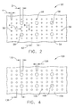
- FIG 4 illustrates a bottom perspective view of an exemplary substrate wall 100 that may be used with gas turbine engine 10 (shown in Figure 1).
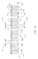
- Figure 5 is a side perspective view of substrate wall 100.
- Wall 100 includes an outer surface 102 and an opposite inner surface 104.
- wall 100 is perforate or porous and includes a plurality of pores 106 distributed across wall 100 in a spaced relationship.
- wall 100 includes film cooling holes 108 that are dispersed across wall amongst pores 106. Pores 106 and holes 108 extend between outer and inner surfaces 102 and 104, respectively.
- each pore 106 includes an exhaust side 110 and an opposite inlet side 112. Holes 108 also each include exhaust and inlet sides 114 and 116, respectively.
- pores 106 and holes 108 extend perpendicularly through wall 100.
- film cooling holes 108 have a frusto-conical shape. Specifically, each hole 108 includes a sloped side wall 118 that extends from exhaust side 114 to inlet side 116.
- hole exhaust side 114 has a first diameter 120 and hole inlet side 116 has a second diameter 122 that is different than hole exhaust side 114.
- first diameter 120 is smaller than second diameter 122. Because of the increases diameter of hole inlet side 116, during operation an increased amount of cooling air 132 is channeled into holes 108.
- pores 106 have a frusto-conical shape. Specifically, each pore 106 includes a sloped side wall 124 extending from exhaust side 110 to inlet side 112.
- pore exhaust side 110 has a first diameter 126 and pore inlet side 112 has a second diameter 128 that is different than pore exhaust side 110.
- first diameter 126 is smaller than second diameter 128.
- first diameter 126 is sized small enough to facilitate being plugged by a thermal barrier coating (TBC) 130, in a similar manner as pore 56 ( Figures 2 and 3), and as described in detail more above.
- TBC thermal barrier coating
- hole first diameter 120 is between approximately eight and fifteen mils, and pore first diameter 126 is between approximately three and five mils. Additionally, in the exemplary embodiment, hole second diameter 122 is between approximately ten and twenty mils, and pore second diameter 128 is between approximately four and six mils. In an alternative embodiment, hole first diameter 120 is between approximately fifteen and forty mils, and pore first diameter 126 is between approximately five and eight mils. Additionally, hole second diameter 122 is between approximately twenty and sixty mils, and pore second diameter 128 is between approximately six and ten mils. In the exemplary embodiment, pores 106 and holes 108 are spaced along wall 100 in a substantially uniform grid-like pattern.
- holes 108 are dispersed along wall 100 amongst pores 106 in a non-uniform manner.
- Hole diameters 120 and 122, and pore diameters 126 and 128 are variably selected to facilitate providing sufficient cooling air 132 through holes 108 and pores 106, while maintaining the structural integrity of wall 100.
- adjacent pores 106 are spaced a distance 136 apart from one another and/or from holes 108.
- distance 136 is between approximately 15 and 40 mils.
- Distance 136 is variably selected to facilitate cooling wall 100 and/or TBC 130.
- a bond coating 134 is applied between wall outer surface 102 and TBC 130 to facilitate enhancing bonding of TBC 130 to wall 100.
- Pores 56 and 106 provide cooling air to facilitate back-side ventilation and cooling of bond coating 76 or 134 and/or TBC 74 or 130. Moreover, pores 56 and 106 facilitate reducing the overall weight of the component. However, because the fabrication of pores 56 or 106 may increase the manufacturing costs of wall 50, TBC 74 or 130 is only selectively applied to those components requiring an enhanced durability and life of TBC 74 or 130, and is generally only applied to areas of individual components that are subject to locally high heat loads. For example, in one embodiment, TBC 74 or 130 is applied only to the platform region of turbine blades 40 (shown in Figure 1).
- TBC 74 or 130 is applied only to the leading and trailing edges (not shown), and/or to the tip regions (not shown) of turbine blades 40.
- the actual location and configuration of TBC 74 or 130 is determined by the cooling and operating requirements of the particular component of gas turbine engine 10 (shown in Figure 1) requiring protection from combustion gases 70.
- the exemplary embodiments described herein illustrate methods and apparatus for cooling components in a gas turbine engine. Because the wall of the component includes a plurality of pores and film cooling holes, the component may be cooled by both a ventilation process and a transpiration process. Utilizing the film cooling holes facilitates cooling an outer surface of the component wall and any TBC extending across the wall outer surface. Moreover, utilizing the pores facilitates cooling an interior of the component wall and the backside of the TBC. Moreover, the pores and holes facilitate reducing the overall weight of the component wall.
- Exemplary embodiments of a substrate wall having a plurality of ventilation pores and film cooling holes are described above in detail.
- the components are not limited to the specific embodiments described herein, but rather, components of each wall may be utilized independently and separately from other components described herein.
- the use of a substrate wall may be used in combination with other known gas turbine engines, and other known gas turbine engine components.
Landscapes
- Engineering & Computer Science (AREA)
- Mechanical Engineering (AREA)
- General Engineering & Computer Science (AREA)
- Chemical & Material Sciences (AREA)
- Combustion & Propulsion (AREA)
- Materials Engineering (AREA)
- Turbine Rotor Nozzle Sealing (AREA)
Applications Claiming Priority (1)
| Application Number | Priority Date | Filing Date | Title |
|---|---|---|---|
| US10/984,292 US7186091B2 (en) | 2004-11-09 | 2004-11-09 | Methods and apparatus for cooling gas turbine engine components |
Publications (2)
| Publication Number | Publication Date |
|---|---|
| EP1655454A1 true EP1655454A1 (fr) | 2006-05-10 |
| EP1655454B1 EP1655454B1 (fr) | 2011-06-15 |
Family
ID=35759126
Family Applications (1)
| Application Number | Title | Priority Date | Filing Date |
|---|---|---|---|
| EP05256817A Expired - Lifetime EP1655454B1 (fr) | 2004-11-09 | 2005-11-03 | Paroi revêtue avec système de refroidissement |
Country Status (4)
| Country | Link |
|---|---|
| US (1) | US7186091B2 (fr) |
| EP (1) | EP1655454B1 (fr) |
| JP (1) | JP4800742B2 (fr) |
| CA (1) | CA2525283C (fr) |
Cited By (15)
| Publication number | Priority date | Publication date | Assignee | Title |
|---|---|---|---|---|
| EP2354453A1 (fr) * | 2010-02-02 | 2011-08-10 | Siemens Aktiengesellschaft | Composant de moteur à turbine pour un refroidissement adaptatif |
| US8087447B2 (en) | 2006-10-30 | 2012-01-03 | United Technologies Corporation | Method for checking wall thickness of hollow core airfoil |
| CN102691533A (zh) * | 2011-03-21 | 2012-09-26 | 通用电气公司 | 带有形成在涂层中的冷却通道的构件和制造方法 |
| CN103009024A (zh) * | 2011-09-23 | 2013-04-03 | 通用电气公司 | 带有冷却通道的构件和制造方法 |
| CN103056604A (zh) * | 2011-10-21 | 2013-04-24 | 通用电气公司 | 具有激光熔覆的部件以及制造方法 |
| CN103711588A (zh) * | 2012-10-05 | 2014-04-09 | 通用电气公司 | 具有自适应冷却通道的涡轮构件 |
| EP2937512A1 (fr) * | 2014-04-23 | 2015-10-28 | United Technologies Corporation | Composant de moteur à turbine à gaz et agencement associé |
| EP3054105A1 (fr) * | 2015-02-03 | 2016-08-10 | General Electric Company | Composant, composant de turbine à gaz et procédé de fabrication associé |
| EP2935836A4 (fr) * | 2012-12-19 | 2016-09-21 | United Technologies Corp | Fermeture de trous de refroidissement avec un agent de remplissage |
| EP2381070A3 (fr) * | 2010-04-22 | 2017-05-31 | General Electric Company | Agencement de refroidissement d'un composant à gaz chaud |
| US9884343B2 (en) | 2012-12-20 | 2018-02-06 | United Technologies Corporation | Closure of cooling holes with a filling agent |
| US10704399B2 (en) | 2017-05-31 | 2020-07-07 | General Electric Company | Adaptively opening cooling pathway |
| US10760430B2 (en) | 2017-05-31 | 2020-09-01 | General Electric Company | Adaptively opening backup cooling pathway |
| US10927680B2 (en) | 2017-05-31 | 2021-02-23 | General Electric Company | Adaptive cover for cooling pathway by additive manufacture |
| US11041389B2 (en) | 2017-05-31 | 2021-06-22 | General Electric Company | Adaptive cover for cooling pathway by additive manufacture |
Families Citing this family (39)
| Publication number | Priority date | Publication date | Assignee | Title |
|---|---|---|---|---|
| WO2006069941A1 (fr) * | 2004-12-24 | 2006-07-06 | Alstom Technology Ltd | Composant comprenant un canal incorpore, en particulier composant a gaz chauds d'une turbomachine |
| US7614235B2 (en) * | 2005-03-01 | 2009-11-10 | United Technologies Corporation | Combustor cooling hole pattern |
| JP5474279B2 (ja) * | 2007-03-06 | 2014-04-16 | 株式会社Ihi | 冷却タービン翼 |
| JP2008309051A (ja) * | 2007-06-14 | 2008-12-25 | Ihi Corp | タービンシュラウドの冷却構造 |
| US8376706B2 (en) * | 2007-09-28 | 2013-02-19 | General Electric Company | Turbine airfoil concave cooling passage using dual-swirl flow mechanism and method |
| US8241001B2 (en) * | 2008-09-04 | 2012-08-14 | Siemens Energy, Inc. | Stationary turbine component with laminated skin |
| US8387397B2 (en) * | 2009-01-27 | 2013-03-05 | General Electric Company | Flow conditioner for use in gas turbine component in which combustion occurs |
| US9416728B2 (en) * | 2009-02-26 | 2016-08-16 | 8 Rivers Capital, Llc | Apparatus and method for combusting a fuel at high pressure and high temperature, and associated system and device |
| US9068743B2 (en) * | 2009-02-26 | 2015-06-30 | 8 Rivers Capital, LLC & Palmer Labs, LLC | Apparatus for combusting a fuel at high pressure and high temperature, and associated system |
| US8986002B2 (en) * | 2009-02-26 | 2015-03-24 | 8 Rivers Capital, Llc | Apparatus for combusting a fuel at high pressure and high temperature, and associated system |
| EP2230455B1 (fr) * | 2009-03-16 | 2012-04-18 | Alstom Technology Ltd | Brûleur pour une turbine à gaz et procédé de refroidissement local d'un flux de gaz chauds passant par un brûleur |
| US8371814B2 (en) * | 2009-06-24 | 2013-02-12 | Honeywell International Inc. | Turbine engine components |
| US8852720B2 (en) | 2009-07-17 | 2014-10-07 | Rolls-Royce Corporation | Substrate features for mitigating stress |
| US20110110772A1 (en) * | 2009-11-11 | 2011-05-12 | Arrell Douglas J | Turbine Engine Components with Near Surface Cooling Channels and Methods of Making the Same |
| US8529193B2 (en) * | 2009-11-25 | 2013-09-10 | Honeywell International Inc. | Gas turbine engine components with improved film cooling |
| US9341118B2 (en) * | 2009-12-29 | 2016-05-17 | Rolls-Royce Corporation | Various layered gas turbine engine component constructions |
| EP2524069B1 (fr) | 2010-01-11 | 2018-03-07 | Rolls-Royce Corporation | Caractéristiques d'atténuation des contraintes méchaniques ou thermiques d'un revêtement de barrière environnementale |
| US8628293B2 (en) | 2010-06-17 | 2014-01-14 | Honeywell International Inc. | Gas turbine engine components with cooling hole trenches |
| US8869889B2 (en) | 2010-09-21 | 2014-10-28 | Palmer Labs, Llc | Method of using carbon dioxide in recovery of formation deposits |
| US8387245B2 (en) * | 2010-11-10 | 2013-03-05 | General Electric Company | Components with re-entrant shaped cooling channels and methods of manufacture |
| US8753071B2 (en) | 2010-12-22 | 2014-06-17 | General Electric Company | Cooling channel systems for high-temperature components covered by coatings, and related processes |
| US20120295061A1 (en) * | 2011-05-18 | 2012-11-22 | General Electric Company | Components with precision surface channels and hybrid machining method |
| US8997495B2 (en) | 2011-06-24 | 2015-04-07 | United Technologies Corporation | Strain tolerant combustor panel for gas turbine engine |
| US9206696B2 (en) | 2011-08-16 | 2015-12-08 | General Electric Company | Components with cooling channels and methods of manufacture |
| US9249670B2 (en) * | 2011-12-15 | 2016-02-02 | General Electric Company | Components with microchannel cooling |
| US9650900B2 (en) | 2012-05-07 | 2017-05-16 | Honeywell International Inc. | Gas turbine engine components with film cooling holes having cylindrical to multi-lobe configurations |
| US10113433B2 (en) | 2012-10-04 | 2018-10-30 | Honeywell International Inc. | Gas turbine engine components with lateral and forward sweep film cooling holes |
| US9200521B2 (en) * | 2012-10-30 | 2015-12-01 | General Electric Company | Components with micro cooled coating layer and methods of manufacture |
| US20140116660A1 (en) * | 2012-10-31 | 2014-05-01 | General Electric Company | Components with asymmetric cooling channels and methods of manufacture |
| WO2014144152A1 (fr) | 2013-03-15 | 2014-09-18 | Rolls-Royce Corporation | Interface de revêtement améliorée |
| US10934853B2 (en) | 2014-07-03 | 2021-03-02 | Rolls-Royce Corporation | Damage tolerant cooling of high temperature mechanical system component including a coating |
| US20170122109A1 (en) * | 2015-10-29 | 2017-05-04 | General Electric Company | Component for a gas turbine engine |
| US10598026B2 (en) | 2016-05-12 | 2020-03-24 | General Electric Company | Engine component wall with a cooling circuit |
| US11021965B2 (en) | 2016-05-19 | 2021-06-01 | Honeywell International Inc. | Engine components with cooling holes having tailored metering and diffuser portions |
| DE102016219424A1 (de) * | 2016-10-06 | 2018-04-12 | Rolls-Royce Deutschland Ltd & Co Kg | Brennkammeranordnung einer Gasturbine sowie Fluggasturbine |
| ES2989187T3 (es) | 2017-03-07 | 2024-11-25 | 8 Rivers Capital Llc | Sistemas y métodos de funcionamiento de una cámara de combustión de combustible flexible para una turbina de gas |
| US10859264B2 (en) | 2017-03-07 | 2020-12-08 | 8 Rivers Capital, Llc | System and method for combustion of non-gaseous fuels and derivatives thereof |
| US11047240B2 (en) | 2017-05-11 | 2021-06-29 | General Electric Company | CMC components having microchannels and methods for forming microchannels in CMC components |
| CA3106955A1 (fr) | 2018-07-23 | 2020-01-30 | 8 Rivers Capital, Llc | Systeme et procede de production d'energie avec une combustion sans flamme |
Citations (5)
| Publication number | Priority date | Publication date | Assignee | Title |
|---|---|---|---|---|
| EP0807744A2 (fr) * | 1996-05-17 | 1997-11-19 | General Electric Company | Article refroidi par fluide et sa méthode de fabrication |
| US20030021905A1 (en) * | 2000-11-06 | 2003-01-30 | Ching-Pang Lee | Method for cooling engine components using multi-layer barrier coating |
| EP1318273A2 (fr) * | 2001-12-07 | 2003-06-11 | Ishikawajima-Harima Heavy Industries Co., Ltd. | Aube de turbine revêtu |
| EP1321629A2 (fr) * | 2001-12-20 | 2003-06-25 | General Electric Company | Couche de barrière thermique ventilée |
| EP1340587A2 (fr) * | 2002-03-01 | 2003-09-03 | General Electric Company | Procédé pour l'enlèvement de revêtement d'un trou traversant un composant et composant traité de cette manière |
Family Cites Families (13)
| Publication number | Priority date | Publication date | Assignee | Title |
|---|---|---|---|---|
| JPS414562Y1 (fr) * | 1965-06-24 | 1966-03-16 | ||
| US5271967A (en) | 1992-08-21 | 1993-12-21 | General Motors Corporation | Method and apparatus for application of thermal spray coatings to engine blocks |
| US5503874A (en) | 1994-09-30 | 1996-04-02 | General Electric Company | Method for low temperature chemical vapor deposition of aluminides containing easily oxidized metals |
| US5494704A (en) | 1994-10-03 | 1996-02-27 | General Electric Company | Low temperature chemical vapor deposition of protective coating containing platinum |
| JPH09144504A (ja) * | 1995-11-22 | 1997-06-03 | Ishikawajima Harima Heavy Ind Co Ltd | タービン冷却翼とその加工方法 |
| EP0780484B1 (fr) | 1995-12-22 | 2001-09-26 | General Electric Company | Articles avec revêtement de barrière thermique et procédé de revêtement |
| EP0925426A1 (fr) | 1996-09-04 | 1999-06-30 | Siemens Aktiengesellschaft | Aube de turbine pouvant etre exposee a un courant gazeux chaud |
| DE19848104A1 (de) | 1998-10-19 | 2000-04-20 | Asea Brown Boveri | Turbinenschaufel |
| US6210488B1 (en) | 1998-12-30 | 2001-04-03 | General Electric Company | Method of removing a thermal barrier coating |
| US6238743B1 (en) | 2000-01-20 | 2001-05-29 | General Electric Company | Method of removing a thermal barrier coating |
| US6408610B1 (en) | 2000-07-18 | 2002-06-25 | General Electric Company | Method of adjusting gas turbine component cooling air flow |
| US6375425B1 (en) | 2000-11-06 | 2002-04-23 | General Electric Company | Transpiration cooling in thermal barrier coating |
| US6478535B1 (en) | 2001-05-04 | 2002-11-12 | Honeywell International, Inc. | Thin wall cooling system |
-
2004
- 2004-11-09 US US10/984,292 patent/US7186091B2/en not_active Expired - Fee Related
-
2005
- 2005-10-26 JP JP2005310643A patent/JP4800742B2/ja not_active Expired - Fee Related
- 2005-11-03 EP EP05256817A patent/EP1655454B1/fr not_active Expired - Lifetime
- 2005-11-03 CA CA2525283A patent/CA2525283C/fr not_active Expired - Fee Related
Patent Citations (5)
| Publication number | Priority date | Publication date | Assignee | Title |
|---|---|---|---|---|
| EP0807744A2 (fr) * | 1996-05-17 | 1997-11-19 | General Electric Company | Article refroidi par fluide et sa méthode de fabrication |
| US20030021905A1 (en) * | 2000-11-06 | 2003-01-30 | Ching-Pang Lee | Method for cooling engine components using multi-layer barrier coating |
| EP1318273A2 (fr) * | 2001-12-07 | 2003-06-11 | Ishikawajima-Harima Heavy Industries Co., Ltd. | Aube de turbine revêtu |
| EP1321629A2 (fr) * | 2001-12-20 | 2003-06-25 | General Electric Company | Couche de barrière thermique ventilée |
| EP1340587A2 (fr) * | 2002-03-01 | 2003-09-03 | General Electric Company | Procédé pour l'enlèvement de revêtement d'un trou traversant un composant et composant traité de cette manière |
Cited By (19)
| Publication number | Priority date | Publication date | Assignee | Title |
|---|---|---|---|---|
| US8087447B2 (en) | 2006-10-30 | 2012-01-03 | United Technologies Corporation | Method for checking wall thickness of hollow core airfoil |
| EP2354453A1 (fr) * | 2010-02-02 | 2011-08-10 | Siemens Aktiengesellschaft | Composant de moteur à turbine pour un refroidissement adaptatif |
| EP2381070A3 (fr) * | 2010-04-22 | 2017-05-31 | General Electric Company | Agencement de refroidissement d'un composant à gaz chaud |
| CN102691533A (zh) * | 2011-03-21 | 2012-09-26 | 通用电气公司 | 带有形成在涂层中的冷却通道的构件和制造方法 |
| CN103009024A (zh) * | 2011-09-23 | 2013-04-03 | 通用电气公司 | 带有冷却通道的构件和制造方法 |
| CN103056604A (zh) * | 2011-10-21 | 2013-04-24 | 通用电气公司 | 具有激光熔覆的部件以及制造方法 |
| CN103711588A (zh) * | 2012-10-05 | 2014-04-09 | 通用电气公司 | 具有自适应冷却通道的涡轮构件 |
| US9617859B2 (en) | 2012-10-05 | 2017-04-11 | General Electric Company | Turbine components with passive cooling pathways |
| EP2935836A4 (fr) * | 2012-12-19 | 2016-09-21 | United Technologies Corp | Fermeture de trous de refroidissement avec un agent de remplissage |
| US9664111B2 (en) | 2012-12-19 | 2017-05-30 | United Technologies Corporation | Closure of cooling holes with a filing agent |
| US9884343B2 (en) | 2012-12-20 | 2018-02-06 | United Technologies Corporation | Closure of cooling holes with a filling agent |
| EP2937512A1 (fr) * | 2014-04-23 | 2015-10-28 | United Technologies Corporation | Composant de moteur à turbine à gaz et agencement associé |
| US9797260B2 (en) | 2014-04-23 | 2017-10-24 | United Technologies Corporation | Engine component with wear surface protection |
| EP3054105A1 (fr) * | 2015-02-03 | 2016-08-10 | General Electric Company | Composant, composant de turbine à gaz et procédé de fabrication associé |
| US9718735B2 (en) | 2015-02-03 | 2017-08-01 | General Electric Company | CMC turbine components and methods of forming CMC turbine components |
| US10704399B2 (en) | 2017-05-31 | 2020-07-07 | General Electric Company | Adaptively opening cooling pathway |
| US10760430B2 (en) | 2017-05-31 | 2020-09-01 | General Electric Company | Adaptively opening backup cooling pathway |
| US10927680B2 (en) | 2017-05-31 | 2021-02-23 | General Electric Company | Adaptive cover for cooling pathway by additive manufacture |
| US11041389B2 (en) | 2017-05-31 | 2021-06-22 | General Electric Company | Adaptive cover for cooling pathway by additive manufacture |
Also Published As
| Publication number | Publication date |
|---|---|
| JP4800742B2 (ja) | 2011-10-26 |
| CA2525283C (fr) | 2013-03-12 |
| EP1655454B1 (fr) | 2011-06-15 |
| US7186091B2 (en) | 2007-03-06 |
| JP2006138624A (ja) | 2006-06-01 |
| US20060099080A1 (en) | 2006-05-11 |
| CA2525283A1 (fr) | 2006-05-09 |
Similar Documents
| Publication | Publication Date | Title |
|---|---|---|
| CA2525283C (fr) | Methodes et dispositif de refroidissement des composants d'une turbine a gaz | |
| US6761956B2 (en) | Ventilated thermal barrier coating | |
| US6749396B2 (en) | Failsafe film cooled wall | |
| EP1245787B1 (fr) | Système de refroidissement d'une extrémité d'aube de turbine revêtue | |
| US8608443B2 (en) | Film cooled component wall in a turbine engine | |
| JP5072277B2 (ja) | 逆向きの流れ膜冷却壁 | |
| US7387488B2 (en) | Cooled turbine shroud | |
| US20130045106A1 (en) | Angled trench diffuser | |
| US20120107135A1 (en) | Apparatus, systems and methods for cooling the platform region of turbine rotor blades | |
| US11352886B2 (en) | Coated components having adaptive cooling openings and methods of making the same | |
| JP6329657B2 (ja) | タービンシュラウドの密封冷却 | |
| EP3321586A2 (fr) | Panneau de chambre de combustion revêtu pour une chambre de combustion de moteur à turbine à gaz | |
| US20170370230A1 (en) | Blade platform cooling in a gas turbine | |
| EP3196419A1 (fr) | Joint d'air extérieure d'aube ayant une couche superficielle avec des poches | |
| US7588412B2 (en) | Cooled shroud assembly and method of cooling a shroud | |
| EP3557005B1 (fr) | Ensemble d'étanchéité doté d'un bouclier pour moteurs à turbine à gaz | |
| EP3514328A1 (fr) | Concept de refroidissement d'un composant de turbine | |
| EP2966261B1 (fr) | Composant de moteur a turbine a gaz refroidi par un film | |
| US20190316479A1 (en) | Air seal having gaspath portion with geometrically segmented coating |
Legal Events
| Date | Code | Title | Description |
|---|---|---|---|
| PUAI | Public reference made under article 153(3) epc to a published international application that has entered the european phase |
Free format text: ORIGINAL CODE: 0009012 |
|
| AK | Designated contracting states |
Kind code of ref document: A1 Designated state(s): AT BE BG CH CY CZ DE DK EE ES FI FR GB GR HU IE IS IT LI LT LU LV MC NL PL PT RO SE SI SK TR |
|
| AX | Request for extension of the european patent |
Extension state: AL BA HR MK YU |
|
| 17P | Request for examination filed |
Effective date: 20061110 |
|
| 17Q | First examination report despatched |
Effective date: 20061208 |
|
| AKX | Designation fees paid |
Designated state(s): DE FR GB IT SE |
|
| GRAP | Despatch of communication of intention to grant a patent |
Free format text: ORIGINAL CODE: EPIDOSNIGR1 |
|
| GRAS | Grant fee paid |
Free format text: ORIGINAL CODE: EPIDOSNIGR3 |
|
| GRAA | (expected) grant |
Free format text: ORIGINAL CODE: 0009210 |
|
| AK | Designated contracting states |
Kind code of ref document: B1 Designated state(s): DE FR GB IT SE |
|
| REG | Reference to a national code |
Ref country code: GB Ref legal event code: FG4D |
|
| REG | Reference to a national code |
Ref country code: DE Ref legal event code: R096 Ref document number: 602005028509 Country of ref document: DE Effective date: 20110728 |
|
| REG | Reference to a national code |
Ref country code: SE Ref legal event code: TRGR |
|
| PLBE | No opposition filed within time limit |
Free format text: ORIGINAL CODE: 0009261 |
|
| STAA | Information on the status of an ep patent application or granted ep patent |
Free format text: STATUS: NO OPPOSITION FILED WITHIN TIME LIMIT |
|
| 26N | No opposition filed |
Effective date: 20120316 |
|
| REG | Reference to a national code |
Ref country code: DE Ref legal event code: R097 Ref document number: 602005028509 Country of ref document: DE Effective date: 20120316 |
|
| PGFP | Annual fee paid to national office [announced via postgrant information from national office to epo] |
Ref country code: SE Payment date: 20131127 Year of fee payment: 9 Ref country code: FR Payment date: 20131118 Year of fee payment: 9 Ref country code: GB Payment date: 20131127 Year of fee payment: 9 Ref country code: DE Payment date: 20131127 Year of fee payment: 9 |
|
| PGFP | Annual fee paid to national office [announced via postgrant information from national office to epo] |
Ref country code: IT Payment date: 20131125 Year of fee payment: 9 |
|
| REG | Reference to a national code |
Ref country code: DE Ref legal event code: R119 Ref document number: 602005028509 Country of ref document: DE |
|
| REG | Reference to a national code |
Ref country code: SE Ref legal event code: EUG |
|
| GBPC | Gb: european patent ceased through non-payment of renewal fee |
Effective date: 20141103 |
|
| PG25 | Lapsed in a contracting state [announced via postgrant information from national office to epo] |
Ref country code: SE Free format text: LAPSE BECAUSE OF NON-PAYMENT OF DUE FEES Effective date: 20141104 |
|
| REG | Reference to a national code |
Ref country code: FR Ref legal event code: ST Effective date: 20150731 |
|
| PG25 | Lapsed in a contracting state [announced via postgrant information from national office to epo] |
Ref country code: GB Free format text: LAPSE BECAUSE OF NON-PAYMENT OF DUE FEES Effective date: 20141103 Ref country code: DE Free format text: LAPSE BECAUSE OF NON-PAYMENT OF DUE FEES Effective date: 20150602 |
|
| PG25 | Lapsed in a contracting state [announced via postgrant information from national office to epo] |
Ref country code: FR Free format text: LAPSE BECAUSE OF NON-PAYMENT OF DUE FEES Effective date: 20141201 |
|
| PG25 | Lapsed in a contracting state [announced via postgrant information from national office to epo] |
Ref country code: IT Free format text: LAPSE BECAUSE OF NON-PAYMENT OF DUE FEES Effective date: 20141103 |