EP1655491A2 - Pompe à vis - Google Patents
Pompe à vis Download PDFInfo
- Publication number
- EP1655491A2 EP1655491A2 EP05024316A EP05024316A EP1655491A2 EP 1655491 A2 EP1655491 A2 EP 1655491A2 EP 05024316 A EP05024316 A EP 05024316A EP 05024316 A EP05024316 A EP 05024316A EP 1655491 A2 EP1655491 A2 EP 1655491A2
- Authority
- EP
- European Patent Office
- Prior art keywords
- rotor
- pump
- outer diameter
- rotors
- power rotor
- Prior art date
- Legal status (The legal status is an assumption and is not a legal conclusion. Google has not performed a legal analysis and makes no representation as to the accuracy of the status listed.)
- Withdrawn
Links
Images

Classifications
-
- F—MECHANICAL ENGINEERING; LIGHTING; HEATING; WEAPONS; BLASTING
- F04—POSITIVE - DISPLACEMENT MACHINES FOR LIQUIDS; PUMPS FOR LIQUIDS OR ELASTIC FLUIDS
- F04C—ROTARY-PISTON, OR OSCILLATING-PISTON, POSITIVE-DISPLACEMENT MACHINES FOR LIQUIDS; ROTARY-PISTON, OR OSCILLATING-PISTON, POSITIVE-DISPLACEMENT PUMPS
- F04C2/00—Rotary-piston machines or pumps
- F04C2/08—Rotary-piston machines or pumps of intermeshing-engagement type, i.e. with engagement of co-operating members similar to that of toothed gearing
- F04C2/082—Details specially related to intermeshing engagement type machines or pumps
- F04C2/084—Toothed wheels
-
- F—MECHANICAL ENGINEERING; LIGHTING; HEATING; WEAPONS; BLASTING
- F04—POSITIVE - DISPLACEMENT MACHINES FOR LIQUIDS; PUMPS FOR LIQUIDS OR ELASTIC FLUIDS
- F04C—ROTARY-PISTON, OR OSCILLATING-PISTON, POSITIVE-DISPLACEMENT MACHINES FOR LIQUIDS; ROTARY-PISTON, OR OSCILLATING-PISTON, POSITIVE-DISPLACEMENT PUMPS
- F04C2/00—Rotary-piston machines or pumps
- F04C2/08—Rotary-piston machines or pumps of intermeshing-engagement type, i.e. with engagement of co-operating members similar to that of toothed gearing
- F04C2/12—Rotary-piston machines or pumps of intermeshing-engagement type, i.e. with engagement of co-operating members similar to that of toothed gearing of other than internal-axis type
- F04C2/14—Rotary-piston machines or pumps of intermeshing-engagement type, i.e. with engagement of co-operating members similar to that of toothed gearing of other than internal-axis type with toothed rotary pistons
- F04C2/16—Rotary-piston machines or pumps of intermeshing-engagement type, i.e. with engagement of co-operating members similar to that of toothed gearing of other than internal-axis type with toothed rotary pistons with helical teeth, e.g. chevron-shaped, screw type
- F04C2/165—Rotary-piston machines or pumps of intermeshing-engagement type, i.e. with engagement of co-operating members similar to that of toothed gearing of other than internal-axis type with toothed rotary pistons with helical teeth, e.g. chevron-shaped, screw type having more than two rotary pistons with parallel axes
Definitions
- the present invention relates to a pump, more particularly to a pump in which pumping is effected by means of at least two intermeshing screw threads, i.e. an intermeshing screw pump.
- Screw pumps in which the pumped fluid is carried between the screw threads on one or more rotors such that the liquid is displaced in a direction generally parallel to the axis of rotation of the or each rotor, are known, and are generally referred to as screw pumps.
- the pump is generally known as an intermeshing screw pump.
- one rotor is provided with one or more helical grooves and another rotor is provided with one or more corresponding helical ridges.
- one of the rotors (the power rotor) is driven by motor, which when activated causes the power rotor to rotate along its longitudinal axis.
- the rotors are mounted in a housing such that their helical screw threads mesh and rotation of the power rotor causes the other rotor or rotors (the idler rotor or rotors) to rotate about its/their longitudinal axis or axes.
- Fluid is drawn into the pump at an inlet or suction end of the pump between the counter-rotating screw threads.
- the rotors turn the meshing of the threads produces fluid chambers bounded by the threads and the pump housing. Fluid becomes trapped in the fluid chambers and continued rotation of the screws causes the fluid chambers to move from the inlet end of the pump to the high pressure outlet end of the pump. Fluid is ejected from the pump at the outlet end as fluid is displaced from the fluid chambers.
- a pump including a power rotor and an idler rotor, the rotors each being provided with a generally helical screw thread and being mounted for rotation in a housing such that the screw threads of the rotors mesh and rotation of one rotor causes rotation of the other rotor, the power rotor being connected to a driving means operation of which causes rotation of the power rotor, wherein the pitch of the threads is less than 1.6 times the outer diameter of the power rotor, the depth of the threads is less than or equal to 0.2 times the outer diameter of the power rotor, and the root diameter of the idler rotor is less than 0.31 times the outer diameter of the power rotor.
- the pitch of the threads i.e. the axial distance between corresponding points on adjacent turns of the thread, is typically twice the outer diameter of the rotors or larger diameter rotor, and may be up to 2.4 times the outer diameter of the rotors or larger diameter rotor.
- a pump according to the invention is shorter than a conventional pump.
- a pump according to the invention may be shorter than a conventional pump.
- a screw pump may be produced which is capable of delivering high pressure fluid and which is more suitable for use in confined spaces such as those found within an engine compartment of an automotive vehicle.
- the thread depth of the screw threads is greater than 0.2 times the diameter of the larger diameter rotor. Whilst, decreasing the thread depth decreases the volume of each fluid chamber, and thus tends to decrease the volume output of the pump, use of a reduced thread depth has particular advantages.
- One advantage of reducing the thread depth is that decreasing the thread depth also decreases the area of leakage paths which permit leakage of fluid from the fluid chambers, and thus reduces leakage from the fluid chambers and hence increases the volumetric efficiency of the pump.
- the overall diameter of a pump according to the invention may be reduced. Rotors with threads of lower depth are also easier and thus less expensive to machine. Thus, a more compact and more efficient pump may be produced at reduced manufacturing cost. Any reduction in output volume may be compensated for by increasing the speed of rotation of the rotors.
- the pitch of the threads is less than or equal to the outer diameter of the power rotor.
- the pitch of the threads may be at least 0.5 times the outer diameter of the power rotor, and may be at least 0.8 times the outer diameter of the power rotor.
- the thread depth of the screw threads is less than 0.175 times the outer diameter of the power rotor, and may be at least 0.1 times the outer diameter of the power rotor.
- the root diameter of the idler rotor is less than 0.3 times the outer diameter of the power rotor, and is ideally at least 0.1 times the outer diameter of the power rotor.
- the root diameter of the idler rotor may be between 0.2 and 0.3 times the outer diameter of the power rotor.
- the length of the power rotor and idler rotor is less than 200mm, and may be less than 100mm.
- the outer diameter of the power rotor is preferably less than 12mm.
- Each rotor may be provided with two generally helical interposed screw threads.
- the pump may include a power rotor and two idler rotors, the power rotor being arranged between the two idler rotors.
- the pitch of the threads is substantially constant over the length of the rotors.
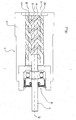
- a pump 10 including a central power rotor 12 and two idler rotors 14a, 14b, all mounted for rotation about their longitudinal axes in a housing 16.
- the power rotor 12 is connected to a driving means by means of a drive shaft 18, in this case an electric motor (not shown) which when activated, causes the power rotor 12 to rotate about its longitudinal axis A.
- the drive shaft 18 is supported in a bearing assembly 28.
- the power rotor 12 has a larger outside diameter than the two idler rotors 14a, 14b.
- Each rotor 12, 14a, 14b is provided with a generally helical screw thread, and the rotors 12, 14a, 14b are arranged in the housing 16, with the power rotor 12 between the two idler rotors 14a, 14b, such that the screw threads mesh.
- the longitudinal axes A, B and C of the rotors 12, 14a are generally parallel, and thus rotation of the power rotor 12 about axis A causes the idler rotors 14a, 14b to rotate about their longitudinal axes, B and C respectively.
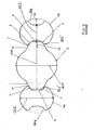
- the rotors 12, 14a, 14b are all provided with two generally helical threads or flights which each extend along substantially the entire length of the rotor 12, 14a, 14b, and which are interposed such that when the rotor 12, 14a, 14b is viewed in transverse cross-section, as shown in Figure 3, one thread is diametrically opposite the other.
- the power rotor 12 has the shape of a generally cylindrical shaft 22 with the threads 20, 20', two generally helical ridges, extending radially outwardly around the shaft 22.
- the idler rotors 14a, 14b each have the shape of a generally cylindrical shaft 24a, 24b with the threads 26a, 26a', 26b, 26b', two generally helical grooves, extending radially inwardly into each shaft 24a, 24b.
- An inlet port (not shown) is provided in the pump housing 16 adjacent a first end of the rotors 12, 14a, 14b and an outlet port 30 is provided in the pump housing 16 adjacent a second, opposite end of the rotors 12, 14a, 14b.
- the pump is operated as follows.
- the motor is activated to cause rotation of the power rotor 12 about axis A, which in turn causes rotation of the idler rotors 14a, 14b in the housing 16 about axes B and C respectively.
- Fluid is drawn into the inlet 28 between the threads 20, 20', 26a, 26a', 26b, 26b' at the first ends of the rotors.
- the meshing of the threads produces fluid chambers bounded by the thread roots R, the thread flanks F and the pump housing 16. Fluid becomes trapped in the fluid chambers and continued rotation of the screws causes the fluid chambers to move from the first end of the rotors 12, 14a, 14b to the second end of the rotors 12, 14a, 14b.
- Fluid is ejected from the pump 10 via the outlet port 30 as a consequence of fluid being displaced from the fluid chamber as the screw threads at the second end of the rotors 12, 14a, 14b mesh.
- each thread 20, 20', 26a, 26a', 26b, 26b' i.e. the distance between corresponding points on adjacent loops of one of the threads 20, 20', 26a, 26a', 26b, 26b', marked as P on Figure 2
- the pitch is less than or equal to and at least 0.5 times the outer diameter ODP of the power rotor 12.
- the pitch P of the threads 20, 20', 26a, 26a', 26b, 26b' is typically from 6 up to 12mm.
- the power rotor outer diameter ODP is 10.8mm and the pitch P is 10.666mm.
- each thread 20, 20', 26a, 26a', 26b, 26b', marked on Figure 3 as TD is less than 0.2 times the outer diameter of the power rotor 12.
- the outer diameter ODP of the power rotor 12 is between 10mm and 12mm and the thread depth TD is between 1.4 and 2mm inclusive.
- the thread depth TD is 1.8mm.
- the root diameter of the idler rotors 14a, 14b is less than 0.31 times the outer diameter ODP of the power rotor 12. If the rotor diameter RDI is too small, for a pump of these dimensions, the idler rotors 14a, 14b would buckle during machining or use, and therefore the root diameter RDI is greater than 0.1 times the outer diameter ODP of the power rotor 12, and is preferably between 0.2 and 0.3 times the outer diameter ODP. In the preferred embodiment of the invention, the root diameter of the idler rotors 14a, 14b is around 3.2mm.
- the outer diameter of the idler rotors 14a, 14b, marked as ODI on Figure 3, is therefore less than or equal to 0.71 times the outer diameter ODP of the power rotor 12, and is preferably less than 0.65 times the outer diameter ODP of the power rotor 12.
- the outer diameter ODI of the idler rotors 14a, 14b is around 6.8mm.
- the pitch P of the threads 20, 20', 26a, 26a', 26b, 26b' is typically twice the outer diameter OD of the power rotor 12, and may be up to 2.4 times the outer diameter OD of the power rotor 12, whereas the thread depth TD is 0.2 times the outer diameter OD of the power rotor 12.
- the pump 10 is shorter than a conventional pump. Since the pressure of fluid output from an intermeshing screw pump 10 depends on the number of fluid chambers formed by the screw threads 20, 20', 26a, 26a', 26b, 26b' of the rotors 12, 14a, 14b, for a given pressure output, the pump 10 may be shorter than a conventional pump.
- the length of the power rotor 12 and the idler rotors 14a, 14b is around 60-70mm, typically 65mm, and the pump 10 is capable of producing fluid pressurised to around 100bar at flow rates of 8-10 litres per minute, depending of the pump speed.
- the overall pump diameter may be smaller than for a conventional pump.
- the pump 10 can be used where space is restricted such as in automotive applications, for example in an electrically operated power pack in which the pump is activated to produce pressurised fluid and the pressurised fluid is used to move an actuator member.
- an electrically powered power pack may be required for applications such as power steering.
- screw pump in such applications as screw pumps are relatively quiet compared with vane and gear pumps, for examples, and require only a relatively small motor in order to run at the high speeds, e.g. over 7,500 rpm, required to produce the fluid volume output needed for such applications.
- the reduction in thread depth TD described above does have a consequence of reducing the volume of each fluid chamber in the pump 10, which in turn reduces the volume output of the pump when operating at a particular speed, but this can be compensated for by increasing the speed of rotation of the pump.
- leakage of fluid from the fluid chambers occurs along leakage paths between the flanks F of the meshing threads 20, 20', 26a, 26a', 26b, 26b', and between the exterior surfaces of the rotors 20, 14a, 14b and the housing 16 or the thread roots R. Such leakage reduces the efficiency of the pump 10.
- Reduction of the thread depth TD reduces the size of the leakage path between the flanks F of meshing threads 20, 20', 26a, 26a', 26b, 26b', and reduction of the pitch reduces the size of the leakage paths between the outer surfaces and the root surfaces R of the rotors 12, 14a, 14b, and it is understood that this contributes towards the improved efficiency of the pump 10.
- the rotors 12, 14a, 14b are typically made by machining the thread forms into a cylindrical metal rod, and the tolerances must be tight in order to ensure that the threads mesh properly without leaving large fluid leakage paths and without the meshing threads becoming jammed during rotation of the rotors 12, 14a, 14b.
- the complexity and hence cost of machining a tight tolerance thread form decreases with a reduced thread depth. This is at least partly because a reduction in root diameter increases the likelihood of the rotor 12, 14a, 14b bending during machining, and thus more care must be taken to produce a thread form of the required low tolerance.
- the root diameter of the rotors 12, 14a, 14b of the present invention is correspondingly larger than the root diameter of rotors of conventional design.
- the rotors 12, 14a, 14b may be provided with fewer or more than two threads or flights per rotor. It would be possible, for example to provide three interposed threads on each rotor 12, 14a, 14b each having a pitch and thread depth as described above.
- the central rotor may be fixed relative to the driving means, and rotation of the rotors achieved by rotation of the pump housing about the longitudinal axis of the central rotor, for example by incorporating the pump housing in the rotor of an electric motor.
Landscapes
- Engineering & Computer Science (AREA)
- Mechanical Engineering (AREA)
- General Engineering & Computer Science (AREA)
- Rotary Pumps (AREA)
Applications Claiming Priority (1)
| Application Number | Priority Date | Filing Date | Title |
|---|---|---|---|
| GB0424557A GB2419920B (en) | 2004-11-08 | 2004-11-08 | Pump |
Publications (2)
| Publication Number | Publication Date |
|---|---|
| EP1655491A2 true EP1655491A2 (fr) | 2006-05-10 |
| EP1655491A3 EP1655491A3 (fr) | 2008-05-28 |
Family
ID=33523288
Family Applications (1)
| Application Number | Title | Priority Date | Filing Date |
|---|---|---|---|
| EP05024316A Withdrawn EP1655491A3 (fr) | 2004-11-08 | 2005-11-08 | Pompe à vis |
Country Status (3)
| Country | Link |
|---|---|
| US (1) | US7234925B2 (fr) |
| EP (1) | EP1655491A3 (fr) |
| GB (1) | GB2419920B (fr) |
Cited By (1)
| Publication number | Priority date | Publication date | Assignee | Title |
|---|---|---|---|---|
| IT202100004148A1 (it) * | 2021-02-23 | 2022-08-23 | Settima Mecc S R L | Assieme di viti per pompa a tre viti e pompa a tre viti comprendente detto assieme |
Families Citing this family (9)
| Publication number | Priority date | Publication date | Assignee | Title |
|---|---|---|---|---|
| US7232297B2 (en) * | 2003-05-08 | 2007-06-19 | Automotive Motion Technology Limited | Screw pump |
| AU2007214341B8 (en) * | 2007-08-31 | 2015-02-19 | Sandvik Intellectual Property Ab | Rock Bolt |
| JP5262393B2 (ja) * | 2008-07-25 | 2013-08-14 | 株式会社アドヴィックス | 3軸ねじポンプ |
| EP2357363B8 (fr) * | 2010-02-12 | 2012-06-06 | Allweiler GmbH | Dispositif de commande pour une pompe volumétrique, système de pompes et procédé de fonctionnement de celui-ci |
| DE102012005949B4 (de) * | 2012-01-31 | 2013-09-12 | Jung & Co. Gerätebau GmbH | Zweispindelige Schraubenspindelpumpe in zweiflutiger Bauweise |
| CN211038693U (zh) * | 2019-10-31 | 2020-07-17 | 何满潮 | Npr锚杆 |
| CN111038466A (zh) * | 2020-01-02 | 2020-04-21 | 徐大江 | 一种液压缓速器 |
| IT202100004139A1 (it) * | 2021-02-23 | 2022-08-23 | Settima Mecc S R L | Assieme di viti per pompa a tre viti e pompa a viti comprendente detto assieme |
| CN113294333B (zh) * | 2021-07-07 | 2025-07-15 | 中国船舶重工集团公司第七0四研究所 | 一种气液混输低噪声三螺杆泵 |
Family Cites Families (29)
| Publication number | Priority date | Publication date | Assignee | Title |
|---|---|---|---|---|
| US630648A (en) * | 1899-04-19 | 1899-08-08 | Robert E Brewer | Rotary engine. |
| US2079083A (en) * | 1935-03-29 | 1937-05-04 | Imo Industri Ab | Fluid meter |
| US2231357A (en) * | 1938-02-04 | 1941-02-11 | Leistritz Maschfabrik Paul | Kneading pump |
| US2481527A (en) * | 1944-06-29 | 1949-09-13 | Jarvis C Marble | Rotary multiple helical rotor machine |
| US2455022A (en) * | 1944-08-08 | 1948-11-30 | Benjamin F Schmidt | Submersible double-acting fluid piston deep well pump |
| US2652192A (en) * | 1947-06-13 | 1953-09-15 | Curtiss Wright Corp | Compound-lead screw compressor or fluid motor |
| US2590560A (en) * | 1948-05-10 | 1952-03-25 | Montelius Carl Oscar Torsten | Screw pump |
| US2588888A (en) * | 1949-02-08 | 1952-03-11 | Laval Steam Turbine Co | Pump |
| CH309671A (de) | 1951-10-25 | 1955-09-15 | Imo Industri Ab | Schraubenpumpe. |
| US2693763A (en) * | 1951-10-25 | 1954-11-09 | Laval Steam Turbine Co | Nonpositive screw pump or motor |
| US2764101A (en) * | 1952-05-27 | 1956-09-25 | Rand Dev Corp | Helical pump |
| CH380861A (de) | 1959-01-28 | 1964-08-15 | Imo Industri Ab | Schraubenpumpe |
| FR1245458A (fr) | 1959-02-04 | 1960-11-04 | Imo Industri Ab | Pompe à engrenages hélicoïdaux |
| CH390690A (de) | 1959-02-23 | 1965-04-15 | Imo Industri Ab | Schraubenpumpe |
| US3063379A (en) * | 1959-02-23 | 1962-11-13 | Laval Steam Turbine Co | Screw pumps |
| GB954426A (en) | 1960-04-22 | 1964-04-08 | Pneumatikus Es Hidraulikus Gep | Improvements in or relating to screw pumps |
| US3253550A (en) * | 1962-05-09 | 1966-05-31 | Laval Turbine | Screw pumps |
| US3291061A (en) * | 1963-07-23 | 1966-12-13 | Kosaka Kenkyusho Ltd | Screw pump or hydraulic screw motor |
| GB1269628A (en) * | 1968-04-19 | 1972-04-06 | Plenty & Son Ltd | Improvements in and relating to inter-meshing screw pumps |
| US3519375A (en) * | 1968-06-18 | 1970-07-07 | Laval Turbine | Screw pumps |
| DE2033201C3 (de) * | 1970-07-04 | 1979-02-01 | Allweiler Ag | Schraubenspindelmotor oder -pumpe |
| US3773444A (en) * | 1972-06-19 | 1973-11-20 | Fuller Co | Screw rotor machine and rotors therefor |
| DE3718863C2 (de) * | 1987-06-05 | 1999-01-28 | Allweiler Ag | Schraubenspindelpumpe |
| EP0925452B9 (fr) * | 1996-09-12 | 2003-02-26 | Ateliers Busch S.A. | Jeu de rotors filetes |
| US6167771B1 (en) | 1998-12-10 | 2001-01-02 | Carrier Corporation | Clearance distribution to reduce the leakage area |
| JP3086217B1 (ja) | 1999-05-07 | 2000-09-11 | 財団法人工業技術研究院 | デュアルスクリュー回転子装置 |
| TW515480U (en) * | 2000-05-12 | 2002-12-21 | Ind Tech Res Inst | Non-symmetrical dual spiral rotors apparatus |
| US6623262B1 (en) * | 2001-02-09 | 2003-09-23 | Imd Industries, Inc. | Method of reducing system pressure pulsation for positive displacement pumps |
| US7232297B2 (en) * | 2003-05-08 | 2007-06-19 | Automotive Motion Technology Limited | Screw pump |
-
2004
- 2004-11-08 GB GB0424557A patent/GB2419920B/en not_active Expired - Fee Related
-
2005
- 2005-11-08 EP EP05024316A patent/EP1655491A3/fr not_active Withdrawn
- 2005-11-08 US US11/269,077 patent/US7234925B2/en not_active Expired - Fee Related
Cited By (3)
| Publication number | Priority date | Publication date | Assignee | Title |
|---|---|---|---|---|
| IT202100004148A1 (it) * | 2021-02-23 | 2022-08-23 | Settima Mecc S R L | Assieme di viti per pompa a tre viti e pompa a tre viti comprendente detto assieme |
| WO2022179746A1 (fr) | 2021-02-23 | 2022-09-01 | Settima Meccanica S.R.L. | Ensemble vis pour pompe à triple vis et pompe à triple vis comprenant ledit ensemble |
| KR20230159435A (ko) | 2021-02-23 | 2023-11-21 | 세티마 메카니카 에스.알.엘. | 삼중 나사 펌프용 나사 조립체 및 상기 조립체를 포함하는 삼중 나사 펌프 (Screw assembly for a triple screw pump and triple screw pump comprising said assembly) |
Also Published As
| Publication number | Publication date |
|---|---|
| GB0424557D0 (en) | 2004-12-08 |
| EP1655491A3 (fr) | 2008-05-28 |
| US7234925B2 (en) | 2007-06-26 |
| GB2419920B (en) | 2009-04-29 |
| US20060216190A1 (en) | 2006-09-28 |
| GB2419920A (en) | 2006-05-10 |
Similar Documents
| Publication | Publication Date | Title |
|---|---|---|
| US7452194B2 (en) | Screw pump | |
| US8142171B2 (en) | Electric pump unit and electric oil pump | |
| JP4888158B2 (ja) | 電動ポンプユニット及び電動オイルポンプ | |
| US7234925B2 (en) | Screw pump | |
| EP1890039A2 (fr) | Pompe à vis | |
| EP1960671B1 (fr) | Pompe a vis pour le pompage de gaz | |
| EP1890038A2 (fr) | Pompe à vis | |
| JP2008196390A (ja) | 容積変動型流体機械 | |
| KR20230159435A (ko) | 삼중 나사 펌프용 나사 조립체 및 상기 조립체를 포함하는 삼중 나사 펌프 (Screw assembly for a triple screw pump and triple screw pump comprising said assembly) | |
| KR20230155473A (ko) | 삼중 나사 펌프용 나사 조립체 및 상기 조립체를 포함하는 나사 펌프 (Screw assembly for a triple screw pump and screw pump comprising said assembly) | |
| EP0361716B1 (fr) | Pompes gerotor | |
| GB2401401A (en) | Three rotor screw pump with smaller central rotor | |
| GB2401400A (en) | Pump with screw pitch less than 1.6 times the diameter | |
| EP1475536B1 (fr) | Pompe rotative améliorée | |
| KR20060047511A (ko) | 스크루식 유체 기계 | |
| CN113574279B (zh) | 螺杆压缩机 | |
| RU55050U1 (ru) | Устройство для перекачивания газожидкостных смесей при технологических операциях в скважинах | |
| KR20180036251A (ko) | 기어펌프 | |
| US20130087002A1 (en) | Internal Gear Machine | |
| KR200343568Y1 (ko) | 트로코이드 기어펌프 | |
| EP1130263A2 (fr) | Pompe à vide à engrenages helicoidaux | |
| EP1475538A2 (fr) | Pompe |
Legal Events
| Date | Code | Title | Description |
|---|---|---|---|
| PUAI | Public reference made under article 153(3) epc to a published international application that has entered the european phase |
Free format text: ORIGINAL CODE: 0009012 |
|
| AK | Designated contracting states |
Kind code of ref document: A2 Designated state(s): AT BE BG CH CY CZ DE DK EE ES FI FR GB GR HU IE IS IT LI LT LU LV MC NL PL PT RO SE SI SK TR |
|
| AX | Request for extension of the european patent |
Extension state: AL BA HR MK YU |
|
| PUAL | Search report despatched |
Free format text: ORIGINAL CODE: 0009013 |
|
| AK | Designated contracting states |
Kind code of ref document: A3 Designated state(s): AT BE BG CH CY CZ DE DK EE ES FI FR GB GR HU IE IS IT LI LT LU LV MC NL PL PT RO SE SI SK TR |
|
| AX | Request for extension of the european patent |
Extension state: AL BA HR MK YU |
|
| STAA | Information on the status of an ep patent application or granted ep patent |
Free format text: STATUS: THE APPLICATION HAS BEEN WITHDRAWN |
|
| RAP1 | Party data changed (applicant data changed or rights of an application transferred) |
Owner name: BUEHLER MOTOR GMBH |
|
| 18W | Application withdrawn |
Effective date: 20080902 |