EP1655574A1 - Laser de construction muni d'un prisme inclinable - Google Patents
Laser de construction muni d'un prisme inclinable Download PDFInfo
- Publication number
- EP1655574A1 EP1655574A1 EP05109880A EP05109880A EP1655574A1 EP 1655574 A1 EP1655574 A1 EP 1655574A1 EP 05109880 A EP05109880 A EP 05109880A EP 05109880 A EP05109880 A EP 05109880A EP 1655574 A1 EP1655574 A1 EP 1655574A1
- Authority
- EP
- European Patent Office
- Prior art keywords
- housing
- laser according
- construction laser
- sliding surface
- construction
- Prior art date
- Legal status (The legal status is an assumption and is not a legal conclusion. Google has not performed a legal analysis and makes no representation as to the accuracy of the status listed.)
- Granted
Links
Images
Classifications
-
- G—PHYSICS
- G01—MEASURING; TESTING
- G01C—MEASURING DISTANCES, LEVELS OR BEARINGS; SURVEYING; NAVIGATION; GYROSCOPIC INSTRUMENTS; PHOTOGRAMMETRY OR VIDEOGRAMMETRY
- G01C15/00—Surveying instruments or accessories not provided for in groups G01C1/00 - G01C13/00
- G01C15/002—Active optical surveying means
- G01C15/004—Reference lines, planes or sectors
-
- Y—GENERAL TAGGING OF NEW TECHNOLOGICAL DEVELOPMENTS; GENERAL TAGGING OF CROSS-SECTIONAL TECHNOLOGIES SPANNING OVER SEVERAL SECTIONS OF THE IPC; TECHNICAL SUBJECTS COVERED BY FORMER USPC CROSS-REFERENCE ART COLLECTIONS [XRACs] AND DIGESTS
- Y10—TECHNICAL SUBJECTS COVERED BY FORMER USPC
- Y10S—TECHNICAL SUBJECTS COVERED BY FORMER USPC CROSS-REFERENCE ART COLLECTIONS [XRACs] AND DIGESTS
- Y10S33/00—Geometrical instruments
- Y10S33/21—Geometrical instruments with laser
Definitions
- the invention relates to a construction laser with a deflecting means, which can be tilted relative to the housing, for a laser beam, in particular a rotational construction laser self-leveling according to the gravitational field, with a rotating laser beam.
- the implementation according to the invention is also applicable to duct lasers or other servo-driven construction lasers (point / line).
- Rotary construction laser with an at least segmentally rotating laser beam are mainly used in the construction industry to set on walls, ceilings and floors horizontal, vertical or defined inclined planes.
- rotary lasers consist of a tiltable in two axes platform on which the position sensor and the rotary head is located.
- the rotary head is adjusted to a few angular seconds relative to this sensor.
- actuators such as stepper motors, which are fixed to the outer housing, this platform can be tilted in two directions by several degrees relative to the housing.
- position sensors dragonflies which are optically read either by CCD lines or with photodiodes.
- a controller reads these sensors for the x and y directions and moves the stepper motors in the appropriate direction until the air bubble of the level is in the calibrated center position.
- the stepper motors are usually stocked with preloaded worm gears in order to obtain the necessary angular accuracy.
- a self-leveling rotary construction laser has a laser unit arranged in a mounting frame, whose laser beam is approximately at 90 ° from a laser Deflection means is deflectable, which is rotatably mounted in a rotation part about an axis of rotation.
- the plane of rotation of the laser beam can be tilted in two mutually perpendicular pivot planes by inclining the rotation axis mounted tiltably in the mounting frame, together with the laser unit and the deflection means, over two actuators with respect to the housing, which is usually oriented horizontally.
- the actuators used with stepper motors and self-locking threaded spindle are structurally complex and prone to failure.
- an electro-optical leveling instrument has a tiltable telescopically mounted in a rotatable lower part, wherein the inclination of the leveling telescope with respect to the lower part by a piezoelectric actuator, which is controllably connected to a control electronics.
- piezoelectric actuators are used in many ways, according to DE3412014C1, DE19817802A1, EP1142039B1 as an actuator, for example for hexapods according to DE19742205A1, EP399975A2, EP0799502B1 as friction force drive for inertial gliders or according to US4987334 as a torsional vibration drive of a laser gyroscope.
- DE3412014C1, DE19817802A1, EP1142039B1 as an actuator, for example for hexapods according to DE19742205A1, EP399975A2, EP0799502B1 as friction force drive for inertial gliders or according to US4987334 as a torsional vibration drive of a laser gyroscope.
- J Fried et al . IEEE / ASME Transactions on Mechatronics; Vol. 9; No. 3
- With a single geometrically complex piezoactuator structure different vibration patterns can be generated on September 7, 2004, depending
- the object of the invention is the realization of a construction laser with a structurally simple actuator for the tiltable to the housing deflection. Another aspect is the downsizing of the housing.
- it has at least one piezoactuator, which is controllably connected to control electronics.
- piezoelectric actuators as an actuator can be dispensed with a complicated reduction ratio and the stepper motor. This also eliminates their space requirements in the housing.
- the housing via a flexible elastic membrane, further advantageously folded, sealed to the inclination part, whereby the interior of the housing is protected with the piezoelectric actuators from contamination.
- At least one with respect to the gravitational field sensitive inclination sensor is advantageously arranged on the inclination part, which is detectably connected to the control electronics, whereby a self-leveling construction laser can be realized via a control loop of the control electronics.
- the deflecting means is rotatably mounted about a rotation axis in the tilting part, whereby the construction laser forms a Rotationsbaulaser with an at least segmentally rotating laser beam.
- the inclination part has a spherical sliding surface, which is mounted in frictional contact directly on the at least three distributed in the housing surface, piezoelectric actuators and which is pressure-biased against this with a biasing means.
- an inertial slider is formed, wherein the inclination part is mediated by applying a sawtooth voltage to the individual piezo actuators on the shear deformation and the inertia of the inclination part in all directions of the spherical surface controllably move, in particular in all three EULER's angles ⁇ , ⁇ and ⁇ .
- the plurality of piezo actuators can also be designed as area-distributed spatial regions of a single, geometrically complex piezoelectric actuator structure, which generate different oscillation patterns as a function of the control frequency.
- the housing has an inverse spherical sliding surface on which, in frictional contact, at least three piezoactuators arranged in a distributed manner in the inclining part are mounted directly.
- the spherical sliding surface is pressure-biased against this piezoelectric actuator with a biasing means, whereby the control electronics can be arranged in the inclination part.
- An inertial glider is a previously known principle that is often used when high-precision but relatively long-distance positioning is required. Relative means here that this principle is not particularly suitable as an absolute positioning method, but is always used in conjunction with a sensor in a control loop. The incremental step size of this principle is very small, so that together with a high-precision absolute position or angle sensor very accurate positioning possible are. Due to the mechanical inertia of the spherical sliding surface and the components thereon, the spherical sliding surface can only follow the slow movements of the piezoelectric actuator, ie only the rising edge of the sawtooth voltage. With the steep, descending flank of the adjacent sawtooth voltage, the piezo elements deform instantly.
- the mass inertia is so great in these accelerations of the piezoelectric actuators that the friction between the piezoelectric actuator and the spherical sliding surface is insufficient to transmit the forces occurring to the spherical sliding surface.
- the piezoelectric actuator deforms back without the spherical sliding surface on it moving.
- the step size in the nm range is given by the height of the sawtooth voltage, their frequency, by the type of piezoelectric actuators and the roughness of the surface of the spherical sliding surface.
- piezoelectric actuators are present, which are distributed in two pairs of piezoelectric actuators along a drive direction, wherein the two drive directions are perpendicular to each other, which can be realized by driving a Piezoaktorfares a separable movement of the spherical sliding surface, in particular a pure inclination with respect to the local Cartesian housing coordinates X and Y fixed pitch axes.
- At least one piezoelectric actuator is mounted on a compression spring means and pressure-biased by this to the ball center, whereby the normal force distributes more uniformly over a plurality of piezoelectric actuators.
- the deflecting means is positioned so that the exit of the laser beam is close to the spherical center of the spherical sliding surface, thereby ensuring that the projection plane generated by the laser beam is tilted precisely around this point.
- the biasing means consists of at least one permanent magnet and its magnetizable counterpart, which are distributed in each case in the housing or in the inclination part, whereby structurally simple a static friction force causing the necessary static friction can be impressed.
- the spherical sliding surface of a magnetizable metal such as iron, whereby it is structurally simple to manufacture by deep drawing and subsequent grinding.
- a plurality of end stops are arranged on the spherical sliding surface, which limit the possible movements in regions, whereby both excessive inclinations and multiple rotations of the spherical sliding surface can be prevented.
- all the piezoelectric actuators are each mounted via a compression spring means and the spherical sliding surface is gimbaled suspended from the housing, whereby the movement is prevented by the rotation angle ⁇ by the compulsion of the cardan suspension, i. in particular a self-rotation of the spherical sliding surface about the axis of rotation.
- the gimbal-mounted on the housing inclination part is at least two angularly offset lever mechanisms with a lever ratio greater 10: 1 with at least one piezoelectric actuator tiltably connected, which by direct deformation of the piezoelectric actuators tilt about an arbitrary inclination axis can be realized.
- a piezoelectric actuator Since a piezoelectric actuator has only very small travel ranges, but can build up very high actuating forces for this purpose, it is useful for positioning purposes to convert the short travel ranges via rigid lever mechanisms with a large lever arm into longer positioning paths.
- the two lever mechanisms are arranged perpendicular to each other, whereby a pure inclination with respect to the local Cartesian housing coordinates X and Y can be realized.
- two piezoactuators arranged parallel to one another form a tilting actuator pair, whereby, in the case of opposite deformation, a respective small linear travel path is converted into an angle tilting ⁇ whose tilting arc is substantially longer.
- the inclination part is formed as a hexapode, which is suspended directly on the housing via at least six piezoactuators, whereby an arbitrary inclination about a virtual pivot point can be set directly via the actuation of the piezoactuators.
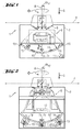
- a construction laser 1 has a laser unit 3 arranged within a partly transparent housing 2 whose laser beam 4 rotating at the angle of rotation ⁇ is deflected by a deflection means 5 rotating about the rotation axis A, which are arranged together with the laser unit 3 in a tilting part 6 is.
- the inclination part 6 is tiltable relative to the housing 2 via an actuator which has four piezoactuators 7 a - 7 d distributed in a planar manner, which are controllably connected to an electronic control unit 8.
- the housing 2 is sealed via a flexible elastic, fold-like shaped membrane 9 to the inclination part 6 out.
- a relative to the gravitational field G sensitive inclination sensor 10 is arranged, which is connected to the control electronics 8 detectable, which via a control algorithm, the piezo actuators 7a, 7b, 7c, 7d as long as to exercise a movement, until the desired inclination ⁇ XY is set to the gravitational field G with respect to a Cartesian Gescousekorrdinatensystems 11 with the two coordinate axes X, Y.
- the housing 2 has an inverse spherical sliding surface 12 on which the inclination part 6 is mounted directly in frictional contact via the four piezoactuators 7a, 7b, 7c, 7d distributed in a planar manner, the fourth piezoactuator 7d itself being in the inclination part 6 via a compression spring means 13 is stored.
- the two Piezoaktorfare 7a + 7b, 7c + 7d are distributed along a respective drive direction along the mutually perpendicular coordinate axes X, Y.
- the exit of the laser beam 4 in the deflection means 5 is located exactly in the ball center of the inverse spherical sliding surface 12.
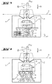
- all four piezoactuators 7a, 7b, 7c, 7d are each mounted via a compression spring means 13 in the housing 2 and connected to the control electronics 8 arranged there, wherein the inclination part 6, which has the spherical sliding surface 12 'formed of polished aluminum, in the ball center itself is gimbaled by a gimbal 16 gimbal on the housing 2.
- the exit of the laser beam 4 rotating in the deflection means 5 with the inclination ⁇ XY in the rotation angle ⁇ is close to the spherical center of the spherical sliding surface 12 '.
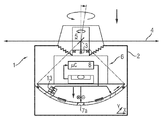
- alternative construction lasers 1 have a laser unit 3 arranged within a partially transparent housing 2, the laser beam 4 of which rotates in the rotational angle ⁇ of a deflection means 5 rotating about the rotation axis A. is deflected, which is arranged together with the laser unit 3 in a tilting part 6.
- the inclination part 6 is tiltable relative to the housing 2 via an actuator which has four piezoactuators 7 a - 7 d distributed in a planar manner, which are controllably connected to an electronic control unit 8.
- the housing 2 is sealed via a flexible elastic, fold-like shaped membrane 9 to the inclination part 6 out.
- the inclination part 6 is formed as a hexapode 18, which is connected directly to the housing 2 via its six mutually skewed piezoelectric actuators 7a, 7b, 7c, 7d, 7e, 7f.
- the fulcrum taken into account by the control algorithm of the control electronics 8 in the control of the piezoelectric actuators 7a, 7b, 7c, 7d, 7e, 7f is located exactly in the outlet of the laser beam 4 rotating in the rotation angle ⁇ with the inclination ⁇ XY in the deflection means 5.
Landscapes
- Physics & Mathematics (AREA)
- Engineering & Computer Science (AREA)
- General Physics & Mathematics (AREA)
- Radar, Positioning & Navigation (AREA)
- Remote Sensing (AREA)
- Mechanical Light Control Or Optical Switches (AREA)
- General Electrical Machinery Utilizing Piezoelectricity, Electrostriction Or Magnetostriction (AREA)
- Gyroscopes (AREA)
Applications Claiming Priority (1)
| Application Number | Priority Date | Filing Date | Title |
|---|---|---|---|
| DE102004053249A DE102004053249B4 (de) | 2004-11-04 | 2004-11-04 | Baulaser mit neigbarem Umlenkmittel |
Publications (2)
| Publication Number | Publication Date |
|---|---|
| EP1655574A1 true EP1655574A1 (fr) | 2006-05-10 |
| EP1655574B1 EP1655574B1 (fr) | 2011-11-30 |
Family
ID=35645799
Family Applications (1)
| Application Number | Title | Priority Date | Filing Date |
|---|---|---|---|
| EP05109880A Expired - Lifetime EP1655574B1 (fr) | 2004-11-04 | 2005-10-24 | Laser de construction muni d'un prisme inclinable |
Country Status (4)
| Country | Link |
|---|---|
| US (1) | US7171756B2 (fr) |
| EP (1) | EP1655574B1 (fr) |
| JP (1) | JP5275544B2 (fr) |
| DE (1) | DE102004053249B4 (fr) |
Families Citing this family (11)
| Publication number | Priority date | Publication date | Assignee | Title |
|---|---|---|---|---|
| TWI261107B (en) * | 2005-02-03 | 2006-09-01 | Asia Optical Co Inc | Laser tilt apparatus and the method thereof |
| DE102005000048A1 (de) * | 2005-04-29 | 2006-11-02 | Hilti Ag | Neigbarer Baulaser |
| DE202008008821U1 (de) * | 2008-08-28 | 2010-02-11 | STABILA Messgeräte Gustav Ullrich GmbH | Laservorrichtung |
| JP5693827B2 (ja) * | 2009-06-17 | 2015-04-01 | 株式会社トプコン | 測量システム |
| CN102607538B (zh) * | 2012-02-28 | 2013-08-21 | 武汉大学 | 一种快速自动安平激光扫平仪自动安平装置及其方法 |
| DE102012017015B4 (de) * | 2012-08-20 | 2015-03-19 | Luphos Gmbh | Verfahren und Vorrichtung zur hochpräzisen Vermessung von Oberflächen |
| JP6173067B2 (ja) * | 2013-06-25 | 2017-08-02 | 株式会社トプコン | レーザ測量機 |
| CN103913152A (zh) * | 2014-04-09 | 2014-07-09 | 上海诺司纬光电仪器有限公司 | 扫平仪的安平控制方法 |
| US9970781B2 (en) * | 2015-03-03 | 2018-05-15 | West Virginia University | Apparatus for three-axis IMU calibration with a single-axis rate table |
| CN115265471B (zh) * | 2022-07-14 | 2023-01-06 | 淄博市交通建设发展中心 | 一种道路施工用勘测系统及方法 |
| CN118533818A (zh) * | 2024-06-14 | 2024-08-23 | 徐州工业职业技术学院 | 一种手持式激光诱导击穿光谱装置 |
Citations (11)
| Publication number | Priority date | Publication date | Assignee | Title |
|---|---|---|---|---|
| DE3412014C1 (de) | 1984-03-31 | 1985-10-17 | Deutsche Forschungs- und Versuchsanstalt für Luft- und Raumfahrt e.V., 5000 Köln | Piezokeramischer Stellantrieb zur Erzeugung von Translationsbewegungen |
| EP0360975A2 (fr) | 1988-09-30 | 1990-04-04 | Rockwell International Corporation | Organe d'actionnement piézoélectrique |
| US4987334A (en) | 1989-08-15 | 1991-01-22 | Northrop Corporation | Piezoelectric dither motor |
| DD291141A5 (de) | 1989-12-28 | 1991-06-20 | Veb Carl Zeiss Jena,De | Anordnung zur zielachsensteuerung, insbesondere von nivellieren |
| DE4406914A1 (de) | 1994-03-03 | 1995-09-07 | Gottlieb Nestle Gmbh & Co Kg | Laser-Theodolit |
| DE19742205A1 (de) | 1997-09-24 | 1998-03-12 | Heinzl Joachim | Mikropositioniereinrichtung |
| EP0854351A2 (fr) | 1997-01-21 | 1998-07-22 | Kabushiki Kaisha Topcon | Instrument d'arpentage à laser |
| EP0799502B1 (fr) | 1994-12-21 | 1999-03-10 | MARCO SYSTEMANALYSE UND ENTWICKLUNG GmbH | Element d'entrainement ou de reglage a actionnement piezo-electrique |
| DE19817802A1 (de) | 1996-11-12 | 1999-10-28 | Marco Systemanalyse Entw | Piezoaktuatorisches Antriebs- oder Verstellelement |
| US20030101605A1 (en) * | 2001-12-04 | 2003-06-05 | Tacklind Christopher A. | Servo-controlled automatic level and plumb tool |
| EP1142039B1 (fr) | 1998-11-30 | 2004-03-24 | MARCO SYSTEMANALYSE UND ENTWICKLUNG GmbH | Element basculant piezoelectrique |
Family Cites Families (20)
| Publication number | Priority date | Publication date | Assignee | Title |
|---|---|---|---|---|
| JP2502165Y2 (ja) * | 1989-10-25 | 1996-06-19 | 株式会社ソキア | 測量機 |
| JP3348385B2 (ja) * | 1993-04-30 | 2002-11-20 | 株式会社ソキア | 基準平面設定装置 |
| US5839199A (en) * | 1993-09-07 | 1998-11-24 | Kabushiki Kaisha Topcon | Laser gradient setting device |
| US5400514A (en) * | 1994-02-22 | 1995-03-28 | Economy Laser, Inc. | Laser instrument for tracing reference lines and other geometric figures |
| JP3558754B2 (ja) * | 1995-09-07 | 2004-08-25 | 株式会社ソキア | 基準面設定装置 |
| CH691931A5 (de) * | 1995-12-21 | 2001-11-30 | Ammann Holding Ag | Laserstrahl-Nivelliergerät sowie Verfahren zum Betrieb eines Laserstrahl-Nivelliergerätes und dazugehöriges Hilfsmittel. |
| DE19646511C1 (de) * | 1996-11-12 | 1998-05-14 | Marco Systemanalyse Entw | Piezoaktuatorisches Antriebs- oder Verstellelement |
| JP4159153B2 (ja) * | 1998-12-03 | 2008-10-01 | 株式会社トプコン | 回転レーザ装置及び受光装置 |
| JP2000180166A (ja) * | 1998-12-15 | 2000-06-30 | Asahi Optical Co Ltd | レーザ測量装置 |
| JP3066828U (ja) * | 1999-08-23 | 2000-03-07 | オプコム インコーポレーション | レ―ザ水準器 |
| JP4317639B2 (ja) * | 2000-03-29 | 2009-08-19 | 株式会社トプコン | レーザ測量機 |
| JP4712212B2 (ja) * | 2001-03-28 | 2011-06-29 | 株式会社トプコン | レーザ照準装置 |
| DE10117465A1 (de) * | 2001-04-06 | 2002-10-10 | Hans Richter | Piezoelektrischer Antrieb |
| DE10119616A1 (de) * | 2001-04-21 | 2002-10-24 | Techno Trans Ges Zur Foerderun | Verstelleinrichtung für ein Mikroskopobjektiv |
| US6848188B2 (en) * | 2001-08-10 | 2005-02-01 | Toolz, Ltd. | Laser alignment device providing multiple references |
| US6892464B2 (en) * | 2002-03-13 | 2005-05-17 | Kabushiki Kaisha Topcon | Laser sighting device |
| FR2840981B1 (fr) * | 2002-06-18 | 2004-09-17 | Agatec | Systeme modulaire de determination de niveau par laser |
| DE10325859B3 (de) * | 2003-06-06 | 2004-06-03 | Hilti Ag | Rotationsbaulaser |
| US6922901B1 (en) * | 2004-01-29 | 2005-08-02 | Chiu Yen Chou | Light leveling device having remote control |
| EP1619468A1 (fr) * | 2004-07-22 | 2006-01-25 | Leica Geosystems AG | Dispositif géodésique avec entraînement piézoélectrique |
-
2004
- 2004-11-04 DE DE102004053249A patent/DE102004053249B4/de not_active Expired - Fee Related
-
2005
- 2005-10-24 EP EP05109880A patent/EP1655574B1/fr not_active Expired - Lifetime
- 2005-10-26 US US11/260,045 patent/US7171756B2/en not_active Expired - Lifetime
- 2005-11-04 JP JP2005321091A patent/JP5275544B2/ja not_active Expired - Lifetime
Patent Citations (11)
| Publication number | Priority date | Publication date | Assignee | Title |
|---|---|---|---|---|
| DE3412014C1 (de) | 1984-03-31 | 1985-10-17 | Deutsche Forschungs- und Versuchsanstalt für Luft- und Raumfahrt e.V., 5000 Köln | Piezokeramischer Stellantrieb zur Erzeugung von Translationsbewegungen |
| EP0360975A2 (fr) | 1988-09-30 | 1990-04-04 | Rockwell International Corporation | Organe d'actionnement piézoélectrique |
| US4987334A (en) | 1989-08-15 | 1991-01-22 | Northrop Corporation | Piezoelectric dither motor |
| DD291141A5 (de) | 1989-12-28 | 1991-06-20 | Veb Carl Zeiss Jena,De | Anordnung zur zielachsensteuerung, insbesondere von nivellieren |
| DE4406914A1 (de) | 1994-03-03 | 1995-09-07 | Gottlieb Nestle Gmbh & Co Kg | Laser-Theodolit |
| EP0799502B1 (fr) | 1994-12-21 | 1999-03-10 | MARCO SYSTEMANALYSE UND ENTWICKLUNG GmbH | Element d'entrainement ou de reglage a actionnement piezo-electrique |
| DE19817802A1 (de) | 1996-11-12 | 1999-10-28 | Marco Systemanalyse Entw | Piezoaktuatorisches Antriebs- oder Verstellelement |
| EP0854351A2 (fr) | 1997-01-21 | 1998-07-22 | Kabushiki Kaisha Topcon | Instrument d'arpentage à laser |
| DE19742205A1 (de) | 1997-09-24 | 1998-03-12 | Heinzl Joachim | Mikropositioniereinrichtung |
| EP1142039B1 (fr) | 1998-11-30 | 2004-03-24 | MARCO SYSTEMANALYSE UND ENTWICKLUNG GmbH | Element basculant piezoelectrique |
| US20030101605A1 (en) * | 2001-12-04 | 2003-06-05 | Tacklind Christopher A. | Servo-controlled automatic level and plumb tool |
Non-Patent Citations (1)
| Title |
|---|
| VON JAMES FRIED, IEEE/ASME TRANSACTIONS ON MECHATRONICS, vol. 9, no. 3, September 2004 (2004-09-01) |
Also Published As
| Publication number | Publication date |
|---|---|
| DE102004053249A1 (de) | 2006-05-11 |
| US7171756B2 (en) | 2007-02-06 |
| US20060090357A1 (en) | 2006-05-04 |
| DE102004053249B4 (de) | 2006-08-17 |
| JP2006133229A (ja) | 2006-05-25 |
| EP1655574B1 (fr) | 2011-11-30 |
| JP5275544B2 (ja) | 2013-08-28 |
Similar Documents
| Publication | Publication Date | Title |
|---|---|---|
| EP1655574B1 (fr) | Laser de construction muni d'un prisme inclinable | |
| US6478434B1 (en) | Cryo micropositioner | |
| CN1068813C (zh) | 机电定位装置 | |
| EP1484578B1 (fr) | Laser rotatif pour la construction | |
| WO2020093577A1 (fr) | Procédé et appareil de stabilisation d'angle d'attitude de balayage laser destinés à un lidar porté par un hélicoptère | |
| US6424077B1 (en) | Manipulator | |
| US10876588B2 (en) | Elastic mechanism | |
| DE102008039468A1 (de) | Vorrichtung und Verfahren zur Lagestabilisierung von Kameras | |
| KR101837327B1 (ko) | XYθ 테이블 장치 | |
| DE69932668T2 (de) | Lasersystem | |
| US6498892B1 (en) | Positioning device especially for assembling optical components | |
| WO2019154466A1 (fr) | Alignement d'un système de balayage résonant | |
| DE102020109341B3 (de) | Stabilisierungsvorrichtung und Verfahren zur Stabilisierung eines Befestigungsbauteils | |
| US20070085450A1 (en) | Motion actuator | |
| US20250205878A1 (en) | Parallel link mechanism | |
| DE69005689T2 (de) | Mechanische Objektplatte, insbesondere für ein Tunneleffektmikroskop. | |
| JPS6153577B2 (fr) | ||
| DE112009005360B4 (de) | Bestimmung einer normalkraft für einen elektromechanischen motor | |
| WO1989000676A1 (fr) | Niveleur a laser avec plan de nivelage reglable | |
| JPS6116167B2 (fr) | ||
| KR102672046B1 (ko) | 지피에스와 연계한 항공촬영 시스템 | |
| Edeler et al. | Development, control and evaluation of a mobile platform for microrobots | |
| TW202316389A (zh) | 運動模擬裝置 | |
| DE102013201604B4 (de) | Kippvorrichtung und Verfahren zum Kippen | |
| DE10119616A1 (de) | Verstelleinrichtung für ein Mikroskopobjektiv |
Legal Events
| Date | Code | Title | Description |
|---|---|---|---|
| PUAI | Public reference made under article 153(3) epc to a published international application that has entered the european phase |
Free format text: ORIGINAL CODE: 0009012 |
|
| AK | Designated contracting states |
Kind code of ref document: A1 Designated state(s): AT BE BG CH CY CZ DE DK EE ES FI FR GB GR HU IE IS IT LI LT LU LV MC NL PL PT RO SE SI SK TR |
|
| AX | Request for extension of the european patent |
Extension state: AL BA HR MK YU |
|
| 17P | Request for examination filed |
Effective date: 20061110 |
|
| AKX | Designation fees paid |
Designated state(s): CH DE FR GB IT LI |
|
| GRAP | Despatch of communication of intention to grant a patent |
Free format text: ORIGINAL CODE: EPIDOSNIGR1 |
|
| GRAS | Grant fee paid |
Free format text: ORIGINAL CODE: EPIDOSNIGR3 |
|
| GRAA | (expected) grant |
Free format text: ORIGINAL CODE: 0009210 |
|
| AK | Designated contracting states |
Kind code of ref document: B1 Designated state(s): CH DE FR GB IT LI |
|
| REG | Reference to a national code |
Ref country code: GB Ref legal event code: FG4D Free format text: NOT ENGLISH Ref country code: CH Ref legal event code: EP |
|
| REG | Reference to a national code |
Ref country code: DE Ref legal event code: R096 Ref document number: 502005012194 Country of ref document: DE Effective date: 20120202 |
|
| PLBE | No opposition filed within time limit |
Free format text: ORIGINAL CODE: 0009261 |
|
| STAA | Information on the status of an ep patent application or granted ep patent |
Free format text: STATUS: NO OPPOSITION FILED WITHIN TIME LIMIT |
|
| 26N | No opposition filed |
Effective date: 20120831 |
|
| REG | Reference to a national code |
Ref country code: DE Ref legal event code: R097 Ref document number: 502005012194 Country of ref document: DE Effective date: 20120831 |
|
| REG | Reference to a national code |
Ref country code: FR Ref legal event code: PLFP Year of fee payment: 12 |
|
| REG | Reference to a national code |
Ref country code: FR Ref legal event code: PLFP Year of fee payment: 13 |
|
| REG | Reference to a national code |
Ref country code: FR Ref legal event code: PLFP Year of fee payment: 14 |
|
| PGFP | Annual fee paid to national office [announced via postgrant information from national office to epo] |
Ref country code: DE Payment date: 20241021 Year of fee payment: 20 |
|
| PGFP | Annual fee paid to national office [announced via postgrant information from national office to epo] |
Ref country code: GB Payment date: 20241022 Year of fee payment: 20 |
|
| PGFP | Annual fee paid to national office [announced via postgrant information from national office to epo] |
Ref country code: FR Payment date: 20241021 Year of fee payment: 20 |
|
| PGFP | Annual fee paid to national office [announced via postgrant information from national office to epo] |
Ref country code: IT Payment date: 20241025 Year of fee payment: 20 |
|
| PGFP | Annual fee paid to national office [announced via postgrant information from national office to epo] |
Ref country code: CH Payment date: 20241101 Year of fee payment: 20 |
|
| REG | Reference to a national code |
Ref country code: CH Ref legal event code: H14 Free format text: ST27 STATUS EVENT CODE: U-0-0-H10-H14 (AS PROVIDED BY THE NATIONAL OFFICE) Effective date: 20251024 Ref country code: DE Ref legal event code: R071 Ref document number: 502005012194 Country of ref document: DE |
|
| REG | Reference to a national code |
Ref country code: GB Ref legal event code: PE20 Expiry date: 20251023 |