EP1655574B1 - Baulaser mit neigbarem Umlenkmittel - Google Patents
Baulaser mit neigbarem Umlenkmittel Download PDFInfo
- Publication number
- EP1655574B1 EP1655574B1 EP05109880A EP05109880A EP1655574B1 EP 1655574 B1 EP1655574 B1 EP 1655574B1 EP 05109880 A EP05109880 A EP 05109880A EP 05109880 A EP05109880 A EP 05109880A EP 1655574 B1 EP1655574 B1 EP 1655574B1
- Authority
- EP
- European Patent Office
- Prior art keywords
- housing
- laser according
- construction laser
- sliding surface
- construction
- Prior art date
- Legal status (The legal status is an assumption and is not a legal conclusion. Google has not performed a legal analysis and makes no representation as to the accuracy of the status listed.)
- Expired - Lifetime
Links
Images

Classifications
-
- G—PHYSICS
- G01—MEASURING; TESTING
- G01C—MEASURING DISTANCES, LEVELS OR BEARINGS; SURVEYING; NAVIGATION; GYROSCOPIC INSTRUMENTS; PHOTOGRAMMETRY OR VIDEOGRAMMETRY
- G01C15/00—Surveying instruments or accessories not provided for in groups G01C1/00 - G01C13/00
- G01C15/002—Active optical surveying means
- G01C15/004—Reference lines, planes or sectors
-
- Y—GENERAL TAGGING OF NEW TECHNOLOGICAL DEVELOPMENTS; GENERAL TAGGING OF CROSS-SECTIONAL TECHNOLOGIES SPANNING OVER SEVERAL SECTIONS OF THE IPC; TECHNICAL SUBJECTS COVERED BY FORMER USPC CROSS-REFERENCE ART COLLECTIONS [XRACs] AND DIGESTS
- Y10—TECHNICAL SUBJECTS COVERED BY FORMER USPC
- Y10S—TECHNICAL SUBJECTS COVERED BY FORMER USPC CROSS-REFERENCE ART COLLECTIONS [XRACs] AND DIGESTS
- Y10S33/00—Geometrical instruments
- Y10S33/21—Geometrical instruments with laser
Definitions
- the invention relates to a construction laser with a deflecting means, which can be tilted relative to the housing, for a laser beam, in particular a rotational construction laser self-leveling according to the gravitational field, with a rotating laser beam.
- the implementation according to the invention is also applicable to duct lasers or other servo-driven construction lasers (point / line).
- Rotary construction laser with an at least segmentally rotating laser beam are mainly used in the construction industry to set on walls, ceilings and floors horizontal, vertical or defined inclined planes.
- rotary lasers consist of a tiltable in two axes platform on which the position sensor and the rotary head is located.
- the rotary head is adjusted to a few angular seconds relative to this sensor.
- actuators such as stepper motors, which are fixed to the outer housing, this platform can be tilted in two directions by several degrees relative to the housing.
- position sensors dragonflies which are optically read either by CCD lines or with photodiodes.
- a controller reads these sensors for the x and y directions and moves the stepper motors in the appropriate direction until the air bubble of the level is in the calibrated center position.
- the stepper motors are usually stocked with preloaded worm gears in order to obtain the necessary angular accuracy.
- a self-leveling rotary construction laser has a laser unit arranged in a mounting frame whose laser beam is approximately at 90 ° from a Deflection means is deflectable, which is rotatably mounted in a rotation part about an axis of rotation.
- EP854351 is the plane of rotation of the laser beam in two mutually perpendicular pivot planes tilted by the tilted in a Kugelkalottenlagerung tilted mounted in the mounting frame axis of rotation together with the laser unit and the deflection over two actuators relative to the mostly horizontally oriented housing is inclined.
- the actuators used with stepper motors and self-locking threaded spindle are structurally complex and prone to failure.
- an electro-optical leveling instrument has a leveling telescope tiltably mounted in a rotatable lower part, wherein the inclination of the leveling telescope with respect to the lower part is effected by a piezoactuator, which is controllably connected to control electronics.
- piezoelectric actuators are widely used, according to the DE3412014C1 . DE19817802A1 .
- EP1142039B1 as an actuator, for example, for hexapod after DE19742205A1 , after EP360975A2 .
- EP0799502B1 as a friction drive with inertial gliders or after the US4987334 as torsional vibration drive of a laser gyroscope.
- the object of the invention is the realization of a construction laser with a structurally simple actuator for the tiltable to the housing deflection. Another aspect is the downsizing of the housing.
- it has at least one piezoactuator, which is controllably connected to control electronics.
- piezoelectric actuators as an actuator can be dispensed with a complicated reduction ratio and the stepper motor. This also eliminates their space requirements in the housing.
- the deflection means is rotatably mounted about an axis of rotation in the inclination part, whereby the construction laser forms a Rotationsbaulaser with an at least segmentally rotating laser beam.
- the housing via a flexible elastic membrane, further advantageously folded, sealed to the inclination part, whereby the interior of the housing is protected with the piezoelectric actuators from contamination.
- At least one with respect to the gravitational field sensitive inclination sensor is advantageously arranged on the inclination part, which is detectably connected to the control electronics, whereby a self-leveling laser can be realized via a control loop of the control electronics.
- the inclination part has a spherical sliding surface, which is mounted in frictional contact directly on the at least three distributed in the housing surface, piezoelectric actuators and which is pressure-biased against this with a biasing means.
- an inertial slider is formed, wherein the inclination part is mediated by applying a sawtooth voltage to the individual piezo actuators on the shear deformation and the inertia of the inclination part in all directions of the ball surface controllably move, in particular in all three EULER's angles ⁇ , ⁇ and ⁇ .
- the plurality of piezo actuators can also be designed as area-distributed spatial regions of a single, geometrically complex piezoelectric actuator structure, which generate different oscillation patterns as a function of the control frequency.
- the housing has an inverse spherical sliding surface on which, in frictional contact, at least three piezoactuators arranged in a distributed manner in the inclination part are mounted directly.
- the spherical sliding surface is pressure-biased against these piezoelectric actuators with a biasing means, whereby the control electronics can be arranged in the inclination part.
- An inertial glider is a previously known principle that is often used when high-precision but relatively long-distance positioning is required. Relative means here that this principle is not particularly suitable as an absolute positioning method, but is always used in conjunction with a sensor in a control loop. The incremental step size of this principle is very small, so that together with a high-precision absolute position or angle sensor very accurate positioning possible are. Due to the mechanical inertia of the spherical sliding surface and the components thereon, the spherical sliding surface can only follow the slow movements of the piezoelectric actuator, ie only the rising edge of the sawtooth voltage. With the steep, descending flank of the adjacent sawtooth voltage, the piezo elements deform instantly.
- the inertia is so great in these accelerations of the piezoelectric actuators that the friction between the piezoelectric actuator and spherical sliding surface is not sufficient to transmit the forces occurring to the spherical sliding surface.
- the piezoelectric actuator deforms back without the spherical sliding surface on it moving.
- the step size in the nm range is given by the height of the sawtooth voltage, their frequency, by the type of piezoelectric actuators and the roughness of the surface of the spherical sliding surface.
- piezoelectric actuators are present, which are distributed in two pairs of piezoelectric actuators along a drive direction, wherein the two drive directions are perpendicular to each other, which can be realized by driving a Piezoaktorfares a separable movement of the spherical sliding surface, in particular a pure inclination with respect to the local Cartesian housing coordinates X and Y fixed pitch axes.
- At least one piezoelectric actuator is mounted on a compression spring means and pressure-biased by this to the ball center, whereby the normal force distributes more uniformly over a plurality of piezoelectric actuators.
- the deflecting means is positioned so that the exit of the laser beam is close to the spherical center of the spherical sliding surface, thereby ensuring that the projection plane generated by the laser beam is tilted precisely around this point.
- the biasing means consists of at least one permanent magnet and its magnetizable counterpart, which are distributed in each case in the housing or in the inclination part, whereby structurally simple a static friction force causing the necessary static friction can be impressed.
- the spherical sliding surface of a magnetizable metal such as iron, whereby it is structurally simple to manufacture by deep drawing and subsequent grinding.
- a plurality of end stops are arranged on the spherical sliding surface, which limit the possible movements in regions, whereby both excessive inclinations and multiple rotations of the spherical sliding surface can be prevented.
- all the piezoelectric actuators are each mounted via a compression spring means and the spherical sliding surface is gimbaled suspended from the housing, whereby the movement is prevented by the rotation angle ⁇ by the compulsion of the cardan suspension, i. in particular a self-rotation of the spherical sliding surface about the axis of rotation.
- the gimbal mounted on the housing inclination part via at least two angularly offset lever mechanisms with a lever ratio greater 10: 1 with at least one piezoelectric actuator tiltably connected, which by direct deformation of the piezoelectric actuators tilt about an arbitrary pitch axis can be realized.
- a piezoelectric actuator Since a piezoelectric actuator has only very small travel ranges, but can build up very high actuating forces for this purpose, it is useful for positioning purposes to convert the short travel ranges via rigid lever mechanisms with a large lever arm into longer positioning paths.
- the two lever mechanisms are arranged perpendicular to each other, whereby a pure inclination with respect to the local Cartesian housing coordinates X and Y can be realized.
- two piezoactuators arranged parallel to one another form a tilting actuator pair, whereby, in the case of opposite deformation, a respective small linear travel path is converted into an angle tilting ⁇ whose tilting arc is substantially longer.
- the inclination part is formed as a hexapod, which is suspended directly on the housing via at least six piezoactuators, whereby an arbitrary inclination about a virtual pivot point can be set directly via the actuation of the piezoactuators.
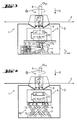
- a construction laser 1 has a laser unit 3 arranged within a partially transparent housing 2 whose laser beam 4 rotating at the angle of rotation ⁇ is deflected by a deflection means 5 rotating about the rotation axis A, which is arranged together with the laser unit 3 in an inclination part 6.
- the inclination part 6 is tiltably adjustable relative to the housing 2 via an actuator, which has four piezoactuators 7 a - 7 d distributed in a planar manner, which are controllably connected to an electronic control unit 8.
- the housing 2 is sealed via a flexible elastic, fold-like shaped membrane 9 to the inclination part 6 out.
- a relative to the gravitational field G sensitive inclination sensor 10 is arranged, which is connected to the control electronics 8 detectable, which via a control algorithm, the piezo actuators 7a, 7b, 7c, 7d as long as to exercise a movement, until the desired inclination ⁇ XY to the gravitational field G with respect to a Cartesian housing coordinate system 11 with the two coordinate axes X, Y is set.
- the housing 2 has an inverse spherical sliding surface 12 on which the inclination part 6 is mounted directly in frictional contact via the four piezoactuators 7a, 7b, 7c, 7d distributed in a planar manner, the fourth piezoactuator 7d itself being in the inclination part 6 via a compression spring means 13 is stored.
- the two Piezoaktorfare 7a + 7b, 7c + 7d are distributed along a respective drive direction along the mutually perpendicular coordinate axes X, Y.
- the exit of the laser beam 4 in the deflection means 5 is located exactly in the ball center of the inverse spherical sliding surface 12.
- Fig. 2 are different from Fig. 1 all four piezoactuators 7a, 7b, 7c, 7d each mounted on a compression spring means 13 in the housing 2 and connected to the control electronics 8 arranged there, wherein the inclination part 6, which forms the spherical sliding surface 12 'of polished aluminum, in the ball center itself via a Cardan suspension 16 is gimbaled to the housing 2.
- the exit of the laser beam 4 rotating in the deflection means 5 with the inclination ⁇ XY in the rotation angle ⁇ is close to the spherical center of the spherical sliding surface 12 '.
- alternative construction lasers 1 have a laser unit 3 arranged within a partly transparent housing 2, the laser beam 4 of which rotates in the rotational angle ⁇ and is guided by a deflection means 5 rotating about the rotation axis A. is deflected, which is arranged together with the laser unit 3 in an inclination part 6.
- the inclination part 6 is tiltably adjustable relative to the housing 2 via an actuator, which has four piezoactuators 7 a - 7 d distributed in a planar manner, which are controllably connected to an electronic control unit 8.
- the housing 2 is sealed via a flexible elastic, fold-like shaped membrane 9 to the inclination part 6 out.
- Fig. 3 is the gimbal mounted via a gimbal 16 gimbals on the housing 2 via two mutually perpendicularly arranged lever mechanisms 17a, 17b with a lever ratio 20: 1, each with a Kippaktorfar of two mutually parallel piezoelectric actuators 7a + 7b, 7c + 7d tiltably connected.
- the exit of the laser beam 4 rotating in the deflection means 5 with the inclination ⁇ XY in the rotation angle ⁇ is located far away from the pivot point of the cardan suspension 16.
- the tilting part 6 is formed as a hexapod 18, which is connected directly to the housing 2 via its six piezoelectric actuators 7a, 7b, 7c, 7d, 7e, 7f which are each offset in a skewed manner.
- the fulcrum taken into account by the control algorithm of the control electronics 8 in the control of the piezoelectric actuators 7a, 7b, 7c, 7d, 7e, 7f is located exactly in the outlet of the laser beam 4 rotating in the rotation angle ⁇ with the inclination ⁇ XY in the deflection means 5.
Landscapes
- Physics & Mathematics (AREA)
- Engineering & Computer Science (AREA)
- General Physics & Mathematics (AREA)
- Radar, Positioning & Navigation (AREA)
- Remote Sensing (AREA)
- Mechanical Light Control Or Optical Switches (AREA)
- General Electrical Machinery Utilizing Piezoelectricity, Electrostriction Or Magnetostriction (AREA)
- Gyroscopes (AREA)
Description
- Die Erfindung betrifft einen Baulaser mit einem gegenüber dem Gehäuse neigbaren Umlenkmittel für einen Laserstrahl, insbesondere einen nach dem Gravitationsfeld selbstnivellierenden Rotationsbaulaser mit einem rotierenden Laserstrahl. Die erfindungsgemässe Realisierung ist zudem auch für Kanalbaulaser oder andere Servobetriebene Baulaser (Punkt / Linie) anwendbar.
- Rotationsbaulaser mit einem zumindest segmentweise rotierenden Laserstrahl werden vor allem im Baugewerbe eingesetzt, um auf Wänden, Decken und Böden horizontale, vertikale oder definiert geneigte Ebenen festzulegen.
- Übliche Rotationslaser bestehen aus einer in zwei Achsen verkippbaren Plattform, auf der sich die Lagesensorik als auch der Rotationskopf befindet. Der Rotationskopf ist relativ zu dieser Sensorik auf einige Winkelsekunden genau justiert. Mit Hilfe von Stellantrieben wie Schrittmotoren, die am äusseren Gehäuse fixiert sind, kann diese Plattform in zwei Richtungen um einige Winkelgrade relativ zum Gehäuse verkippt werden. Als Lagesensoren kommen Libellen zum Einsatz, die optisch entweder mittels CCD-Zeilen oder mit Photodioden ausgelesen werden. Eine Regelung liest diese Sensoren für die x- und y-Richtung aus und verfährt die Schrittmotoren in die entsprechende Richtung solange, bis sich die Luftblase der Libelle in der geeichten Mittenposition befindet. Die Schrittmotoren sind meist mit vorgespannten Schneckengetrieben untersetzt, um die notwendige Winkelgenauigkeit zu erhalten. Nachteile dieser Konstruktion sind die Baugrösse, das Gewicht der Schrittmotoren und die Kosten des Aufbaus. Ausserdem können sich die Schneckengetriebe an beiden Endanschlägen verklemmen. Die Tatsache, dass der Antrieb sehr stark untersetzt ist, kann dazu führen, dass es an den mechanischen Endanschlägen zu einer mechanischen Selbsthemmung kommt. Der Schrittmotor fährt an diesen Endanschlag, die Schnecke wird gehemmt. Das Motormoment reicht dann nicht aus, das Getriebe aus dieser Selbsthemmung zu befreien.
- Nach der
DE4406914 weist ein selbstnivellierender Rotationsbaulaser eine in einem Montagerahmen angeordnete Lasereinheit auf, deren Laserstrahl etwa um 90° von einem Umlenkmittel umlenkbar ist, das in einem Rotationsteil um eine Drehachse drehbar gelagert ist. - Nach der
EP854351 - Nach der
DD291141 - Nach der
US2003101605 weist ein Baulaser in einem Gehäuse eine Lasereinheit auf, deren Laserstrahl von einem Umlenkmittel umgelenkt ist, das gemeinsam mit der Lasereinheit in einem Neigungsteil angeordnet ist, welches zum Gehäuse über einen Stellantrieb verstellbar ist, der einen Aktuator aufweist, der mit einer Steuerelektronik steuerbar verbunden ist. - Zudem werden Piezoaktoren vielfältig verwendet, nach der
DE3412014C1 ,DE19817802A1 ,EP1142039B1 als Stellantrieb bspw. für Hexapode nachDE19742205A1 , nach derEP360975A2 EP0799502B1 als Reibkraftantrieb bei Trägheitsgleitern oder nach derUS4987334 als Drehschwingantrieb eines Lasergyroskops. Nach dem Fachartikel von James Fried et al.; IEEE/ASME Transactions on Mechatronics; Vol. 9; No. 3; Sept. 2004 sind mit einer einzigen geometrisch komplexen Piezoaktorstruktur zudem an versetzten Raumbereichen verschiedene Schwingungsmuster abhängig von der Steuerfrequenz erzeugbar. - Die Aufgabe der Erfindung besteht in der Realisierung eines Baulasers mit einem konstruktiv einfachen Stellantrieb für die zum Gehäuse neigbaren Umlenkmittel. Ein weiterer Aspekt besteht in der Verkleinerung des Gehäuses.
- Die Aufgabe wird im Wesentlichen durch die Merkmale des unabhängigen Anspruchs gelöst. Vorteilhafte Weiterbildungen ergeben sich aus den abhängigen Ansprüchen.
- So weist ein Baulaser in einem Gehäuse eine Lasereinheit auf, deren Laserstrahl von einem Umlenkmittel umgelenkt ist, das gemeinsam mit der Lasereinheit in einem Neigungsteil angeordnet ist, welches zum Gehäuse über einen Stellantrieb verstellbar ist. Der weist dabei zumindest einen Piezoaktor auf, der mit einer Steuerelektronik steuerbar verbunden ist.
- Durch die Verwendung von Piezoaktoren als Stellantrieb kann auf eine komplizierte Untersetzung und auf den Schrittmotor verzichtet werden. Dadurch entfällt zudem deren Raumbedarf im Gehäuse.
- Erfindungsgemäß ist in dem Neigungsteil das Umlenkmittel um eine Drehachse drehbar gelagert, wodurch der Baulaser einen Rotationsbaulaser mit einem zumindest segmentweise rotierenden Laserstrahl ausbildet.
- Vorteilhaft ist das Gehäuse über eine flexible elastische Membran, weiter vorteilhaft gefaltet, zu dem Neigungsteil hin abgedichtet, wodurch das Innere des Gehäuses mit den Piezoaktoren vor Verunreinigungen geschützt ist.
- Vorteilhaft ist an dem Neigungsteil zumindest ein bezüglich des Gravitationsfeldes sensibler Neigungssensor angeordnet, der mit der Steuerelektronik erfassbar verbunden ist, wodurch über eine Regelschleife der Steuerelektronik ein selbstnivellierender Baulaser realisierbar ist.
- Vorteilhaft weist das Neigungsteil eine sphärische Gleitfläche auf, die im Reibkontakt direkt auf den zumindest drei, im Gehäuse flächig verteilt angeordneten, Piezoaktoren gelagert ist und die gegen diese mit einem Vorspannmittel druckvorgespannt ist. Hierdurch wird ein Trägheitsgleiter ausbildet, wobei sich das Neigungsteil durch Anlegen einer Sägezahnspannung an die einzelnen Piezoaktoren vermittelt über deren Scherdeformation und die Massenträgheit des Neigungsteils in allen Richtungen der Kugeloberfläche steuerbar bewegen lässt, insbesondere in allen drei EULERschen Winkeln Θ, Φ und Ψ. Die mehreren Piezoaktoren können dabei wirkungsgleich selbst auch als flächig verteilte Raumbereiche einer einzelnen, geometrisch komplexen Piezoaktorstruktur ausgebildet sein, die abhängig von der Steuerfrequenz unterschiedliche Schwingungsmuster erzeugen.
- Alternativ weist das Gehäuse eine inverse sphärische Gleitfläche auf, auf der im Reibkontakt direkt zumindest drei, im Neigungsteil flächig verteilt angeordnete, Piezoaktoren gelagert sind. Die sphärische Gleitfläche ist gegen diese Piezoaktoren mit einem Vorspannmittel druckvorgespannt, wodurch die Steuerelektronik im Neigungsteil angeordnet werden kann.
- Ein Trägheitsgleiter ist ein vorbekanntes Prinzip, das oft dann zur Anwendung kommt, wenn über längere Distanzen hochgenau, jedoch relativ positioniert werden soll. Relativ heisst hier, dass sich dieses Prinzip nicht besonders eignet als absolute Positioniermethode, sondern immer in Verbindung mit einem Sensor in einem Regelkreis verwendet wird. Die inkrementelle Schrittweite dieses Prinzips ist sehr klein, sodass zusammen mit einem hochgenauen absoluten Positions- oder Winkelsensor sehr genaue Positionierungen möglich sind. Durch die mechanische Massenträgheit der sphärischen Gleitfläche und der darauf befindlichen Bauteile, vermag die sphärische Gleitfläche nur den langsamen Bewegungen der Piezoaktors zu folgen, d.h. nur der steigenden Flanke der Sägezahnspannung. Bei der steilen, absteigenden Flanke der anliegenden Sägezahnspannung verformen sich die Piezoelemente augenblicklich zurück. Die Massenträgheit ist bei diesen Beschleunigungen der Piezoaktoren so gross, dass die Reibung zwischen Piezoaktor und sphärischer Gleitfläche nicht ausreicht, um die auftretenden Kräfte auf die sphärische Gleitfläche zu übertragen. Der Piezoaktor verformt sich zurück, ohne dass sich die darauf befindliche sphärische Gleitfläche mitbewegt. Die Schrittweite im nm-Bereich ist dabei durch die Höhe der Sägezahnspannung, deren Frequenz, durch die Art der Piezoaktoren und die Rauheit der Oberfläche der sphärischen Gleitfläche gegeben.
- Vorteilhaft sind genau vier Piezoaktoren vorhanden, die in zwei Piezoaktorpaare längs je einer Antriebsrichtung verteilt sind, wobei die beiden Antriebsrichtungen senkrecht zueinander stehen, wodurch sich durch Ansteuerung je eines Piezoaktorpaares eine separierbare Bewegung der sphärischen Gleitfläche realisieren lässt, insbesondere eine reine Neigung um bezüglich der lokalen kartesischen Gehäuseskoordinaten X und Y feste Neigungsachsen.
- Vorteilhaft ist zumindest ein Piezoaktor über ein Druckfedermittel gelagert und durch dieses zum Kugelmittelpunkt druckvorgespannt, wodurch sich die Normalkraft gleichmässiger über mehrere Piezoaktoren verteilt.
- Vorteilhaft ist das Umlenkmittel so positioniert, dass sich der Austritt des Laserstrahls nahe des Kugelmittelpunktes der sphärischen Gleitfläche befindet, wodurch gewährleistet wird, dass die Projektionsebene, die der Laserstrahl erzeugt, genau um diesen Punkt verkippt wird.
- Vorteilhaft besteht das Vorspannmittel aus zumindest einem Permanentmagneten und seinem magnetisierbaren Gegenstück, welche jeweils im Gehäuse bzw. im Neigungsteil verteilt angeordnet sind, wodurch konstruktiv einfach eine die nötige Haftreibung bewirkende statische Normalkraft aufprägbar ist.
- Vorteilhaft besteht die sphärische Gleitfläche aus einem magnetisierbaren Metall wie Eisen, wodurch es durch Tiefziehen und anschliessendem Überschleifen konstruktiv einfach herstellbar ist.
- Vorteilhaft sind an der sphärischen Gleitfläche mehrere Endanschläge angeordnet, welche die möglichen Bewegungen bereichsweise begrenzen, wodurch sowohl übergrosse Neigungen als auch Mehrfachdrehungen der sphärischen Gleitfläche unterbunden werden können.
- Alternativ vorteilhaft sind alle Piezoaktoren je über ein Druckfedermittel gelagert sowie die sphärische Gleitfläche kardanisch am Gehäuse aufgehängt, wodurch die Bewegung um den Drehwinkel Φ durch den Zwang der Kardanaufhängung unterbunden wird, d.h. insbesondere eine Eigenrotation der sphärischen Gleitfläche um die Drehachse.
- Alternativ ist das kardanisch am Gehäuse gelagerte Neigungsteil über zumindest zwei winkelig versetzte Hebelmechanismen mit einem Hebelverhältnis grösser 10 : 1 mit zumindest je einem Piezoaktor neigbar verbunden, wodurch durch direkte Deformation der Piezoaktoren eine Neigung um eine beliebige Neigungsachse realisierbar ist.
- Da ein Piezoaktor nur sehr geringe Stellwege aufweist, aber dafür sehr hohe Stellkräfte aufbauen kann, ist es für Positionierzwecke nützlich, die kurzen Stellwege über starre Hebelmechanismen mit grossem Hebelarm in längere Positionierwege umzuwandeln.
- Vorteilhaft sind die zwei Hebelmechanismen zueinander senkrecht angeordnet, wodurch eine reine Neigung bezüglich der lokalen kartesischen Gehäusekoordinaten X und Y realisierbar ist.
- Vorteilhaft bilden zwei parallel zueinander angeordnete Piezoaktoren ein Kippaktorpaar aus, wodurch bei entgegengesetzter Deformation je ein geringer linearer Stellweg in eine Winkelverkippung α umgewandelt wird, deren Kippbogen wesentlich länger ist.
- Alternativ ist das Neigungsteil als Hexapode ausgebildet, das über zumindest sechs Piezoaktoren direkt am Gehäuse aufgehängt ist, wodurch direkt über die Ansteuerung der Piezoaktoren eine beliebige Neigung um einen virtuellen Drehpunkt einstellbar ist.
- Die Erfindung wird bezüglich eines vorteilhaften Ausführungsbeispiels näher erläutert mit:
-
Fig. 1 als selbstnivellierender Rotationsbaulaser mit Permanentmagneten -
Fig. 2 als Alternative mit Kardanaufhängung -
Fig. 3 als Alternative mit Piezoaktor-Hebel -
Fig. 4 als Alternative mit Piezoaktor-Hexapode - Nach
Fig. 1 weist ein Baulaser 1 eine innerhalb eines teils transparenten Gehäuses 2 angeordnete Lasereinheit 3 auf, deren im Drehwinkel Φ rotierender Laserstrahl 4 von einem um die Drehachse A drehenden Umlenkmittel 5 umgelenkt ist, das gemeinsam mit der Lasereinheit 3 in einem Neigungsteil 6 angeordnet ist. Das Neigungsteil 6 ist zum Gehäuse 2 über einen Stellantrieb neigbar verstellbar, der vier flächig verteilte Piezoaktoren 7a - 7d aufweist, die mit einer Steuerelektronik 8 steuerbar verbunden sind. Das Gehäuse 2 ist über eine flexible elastische, faltenartig geformte Membran 9 zu dem Neigungsteil 6 hin abgedichtet. An dem Neigungssteil 6 ist ein bezüglich des Gravitationsfeldes G sensibler Neigungssensor 10 angeordnet, der mit der Steuerelektronik 8 erfassbar verbunden ist, welche über einen Regelalgorithmus die Piezoaktoren 7a, 7b, 7c, 7d solange zur Ausübung einer Bewegung ansteuert, bis die gewünschte Neigung ΘXY zum Gravitationsfeld G bezüglich eines kartesischen Gehäusekoordinatensystems 11 mit den beiden Koordinatenachsen X, Y eingestellt ist. Das Gehäuse 2 weist eine inverse sphärische Gleitfläche 12 auf, auf denen das Neigungsteil 6 über die vier darin flächig verteilt angeordneten Piezoaktoren 7a, 7b, 7c, 7d direkt im Reibkontakt gelagert ist, wobei der vierte Piezoaktor 7d selbst über ein Druckfedermittel 13 im Neigungsteil 6 gelagert ist. Die zwei Piezoaktorpaare 7a+7b, 7c+7d sind längs je einer Antriebsrichtung längs der zueinander senkrecht stehenden Koordinatenachsen X, Y verteilt. Der Austritt des Laserstrahls 4 im Umlenkmittel 5 befindet sich exakt im Kugelmittelpunkt der inversen sphärischen Gleitfläche 12. Im Neigungsteil 6 sind Permanentmagneten 14 angeordnet, welche über die aus verchromten Eisenblech bestehende inverse sphärische Gleitfläche 12 als magnetisierbares Gegenstück den Reibkontakt der Piezoaktoren 7a, 7b, 7c, 7d mit der Normalkraft FN druckvorspannen. An der sphärischen Gleitfläche 12 sind beidseitige Endanschläge 15 angeordnet. - Nach der
Fig. 2 sind im Unterschied zurFig. 1 alle vier Piezoaktoren 7a, 7b, 7c, 7d jeweils über ein Druckfedermittel 13 im Gehäuse 2 gelagert und mit der dort angeordneten Steuerelektronik 8 verbunden, wobei das Neigungsteil 6, welches die sphärische Gleitfläche 12' aus poliertem Aluminium ausbildet, in deren Kugelmittelpunkt selbst über eine Kardanaufhängung 16 kardanisch am Gehäuse 2 aufgehängt ist. Der Austritt des mit der Neigung ΘXY im Drehwinkel Φ rotierenden Laserstrahls 4 im Umlenkmittel 5 befindet sich nahe des Kugelmittelpunktes der sphärischen Gleitfläche 12'. - Nach den
Fig. 3 und Fig. 4 weisen alternative Baulaser 1 eine innerhalb eines teils transparenten Gehäuses 2 angeordnete Lasereinheit 3 auf, deren im Drehwinkel Φ rotierender Laserstrahl 4 von einem um die Drehachse A drehenden Umlenkmittel 5 umgelenkt ist, das gemeinsam mit der Lasereinheit 3 in einem Neigungsteil 6 angeordnet ist. Das Neigungsteil 6 ist zum Gehäuse 2 über einen Stellantrieb neigbar verstellbar, der vier flächig verteilte Piezoaktoren 7a - 7d aufweist, die mit einer Steuerelektronik 8 steuerbar verbunden sind. Das Gehäuse 2 ist über eine flexible elastische, faltenartig geformte Membran 9 zu dem Neigungsteil 6 hin abgedichtet. An dem Neigungsteil 6 ist ein bezüglich des Gravitationsfeldes G sensibler Neigungssensor 10 angeordnet, der mit der Steuerelektronik 8 erfassbar verbunden ist, welche über einen Regelalgorithmus die Piezoaktoren 7a, 7b, 7c, 7d solange deformiert, bis die gewünschte Neigung ΘXY zum Gravitationsfeld G bezüglich eines kartesischen Gehäusekoordinatensystems 11 mit den beiden Koordinatenachsen X, Y eingestellt ist. - Bei
Fig. 3 ist das über eine Kardanaufhängung 16 kardanisch am Gehäuse 2 gelagerte Neigungsteil 6 über zwei zueinander senkrecht angeordnete Hebelmechanismen 17a, 17b mit einem Hebelverhältnis 20 : 1 mit je einem Kippaktorpaar aus je zwei parallel zueinander angeordneten Piezoaktoren 7a+7b, 7c+7d neigbar verbunden. Der Austritt des mit der Neigung ΘXY im Drehwinkel Φ rotierenden Laserstrahls 4 im Umlenkmittel 5 befindet sich jedoch weit entfernt vom Drehpunkt der Kardanaufhängung 16. - Bei
Fig. 4 ist das Neigungsteil 6 als Hexapode 18 ausgebildet, welches über seine sechs zueinander jeweils windschief versetzt angeordnete Piezoaktoren 7a, 7b, 7c, 7d, 7e, 7f direkt mit dem Gehäuse 2 verbunden ist. Der vom Regelalgorithmus der Steuerelektronik 8 bei der Ansteuerung der Piezoaktoren 7a, 7b, 7c, 7d, 7e, 7f berücksichtigte Drehpunkt befindet sich exakt im Austritt des mit der Neigung ΘXY im Drehwinkel Φ rotierenden Laserstrahls 4 im Umlenkmittel 5.
Claims (16)
- Baulaser mit einer Lasereinheit (3), deren Laserstrahl (4) von einem Umlenkmittel (5) umgelenkt ist, das gemeinsam mit der Lasereinheit (3) in einem Neigungsteil (6) angeordnet ist, welches zu einem Gehäuse (2) über einen Stellantrieb verstellbar ist, wobei der Stellantrieb zumindest einen Aktuator aufweist, der mit einer Steuerelektronik (8) steuerbar verbunden ist, dadurch gekennzeichnet, dass in dem Neigungsteil (6) das Umlenkmittel (5) um eine Drehachse (A) drehbar gelagert ist und dass der Aktuator ein Piezoaktor (7a) ist.
- Baulaser nach Anspruch 1, dadurch gekennzeichnet, dass das Gehäuse (2) über eine, optional faltenartig geformte, flexible elastische Membran (9) zu dem Neigungsteil (6) hin abgedichtet ist.
- Baulaser nach Anspruch 1 oder 2, dadurch gekennzeichnet, dass an dem Neigungsteil (6) zumindest ein bezüglich des Gravitationsfeldes (G) sensibler Neigungssensor (10) angeordnet ist, der mit der Steuerelektronik (8) erfassbar verbunden ist.
- Baulaser nach einem der Ansprüche 1 bis 3, dadurch gekennzeichnet, dass das Neigungsteil (6) eine sphärische Gleitfläche (12) aufweist, die im Reibkontakt direkt auf den zumindest drei, im Gehäuse (2) flächig verteilt angeordnete, Piezoaktoren (7a, 7b, 7c) gelagert und gegen diese mit einem Vorspannmittel druckvorgespannt ist.
- Baulaser nach einem der Ansprüche 1 bis 3, dadurch gekennzeichnet, dass das Gehäuse (2) eine inverse sphärische Gleitfläche (12') aufweist, auf der im Reibkontakt direkt zumindest drei, im Neigungsteil (6) flächig verteilt angeordnete, Piezoaktoren (7a, 7b, 7c) gelagert sind und die gegen diese mit einem Vorspannmittel druckvorgespannt ist.
- Baulaser nach Anspruch 4 oder 5, dadurch gekennzeichnet, dass genau vier Piezoaktoren (7a, 7b, 7c, 7d) vorhanden sind, die als zwei Piezoaktorpaare (7a+7b, 7c+7d) je längs einer, zueinander senkrechten, Antriebsrichtung verteilt sind.
- Baulaser nach einem der Ansprüche 4 bis 6, dadurch gekennzeichnet, dass zumindest ein Piezoaktor (7d) über ein Druckfedermittel (13) im Gehäuse (2) gelagert und durch dieses zum Kugelmittelpunkt hin druckvorgespannt ist.
- Baulaser nach einem der Ansprüche 4 bis 7, dadurch gekennzeichnet, dass das Umlenkmittel (5) so positioniert ist, dass sich der Austritt des Laserstrahls (4) nahe des Kugelmittelpunktes der sphärischen Gleitfläche (12, 12') befindet.
- Baulaser nach einem der Ansprüche 4 bis 8, dadurch gekennzeichnet, dass das Vorspannmittel aus zumindest einem Permanentmagneten (14) und seinem magnetisierbaren Gegenstück besteht, welche jeweils im Gehäuse (2) bzw. im Neigungsteil (6) verteilt angeordnet sind.
- Baulaser nach einem der Ansprüche 4 bis 9, dadurch gekennzeichnet, dass die sphärische Gleitfläche (12, 12') aus einem magnetisierbaren Metall besteht.
- Baulaser nach einem der Ansprüche 4 bis 10, dadurch gekennzeichnet, dass an der sphärischen Gleitfläche (12, 12') mehrere Endanschläge (15) angeordnet sind, welche die möglichen Bewegungen bereichsweise begrenzen.
- Baulaser nach einem der Ansprüche 4 bis 11, dadurch gekennzeichnet, dass alle Piezoaktoren (7a, 7b, 7c) je über ein Druckfedermittel (13) gelagert sind sowie die sphärische Gleitfläche (12) kardanisch am Gehäuse (2) aufgehängt ist.
- Baulaser nach einem der Ansprüche 1 bis 3, dadurch gekennzeichnet, dass das kardanisch am Gehäuse (2) gelagerte Neigungsteil (6) über zumindest zwei winkelig versetzte Hebelmechanismen (17a, 17b) mit einem Hebelverhältnis grösser 10 : 1 mit zumindest je einem Piezoaktor (7a, 7c) neigbar verbunden ist.
- Baulaser nach Anspruch 13, dadurch gekennzeichnet, dass die zwei Hebelmechanismen (17a, 17b) zueinander senkrecht angeordnet sind.
- Baulaser nach Anspruch 13 oder 14, dadurch gekennzeichnet, dass zwei parallel zueinander angeordnete Piezoaktoren (7a+7b) ein Kippaktorpaar ausbilden.
- Baulaser nach einem der Ansprüche 1 bis 3, dadurch gekennzeichnet, dass das Neigungsteil (6) als Hexapode (18) ausgebildet ist, das über zumindest sechs Piezoaktoren (7a, 7b, 7c, 7d, 7e, 7f) direkt am Gehäuse (2) aufgehängt ist.
Applications Claiming Priority (1)
| Application Number | Priority Date | Filing Date | Title |
|---|---|---|---|
| DE102004053249A DE102004053249B4 (de) | 2004-11-04 | 2004-11-04 | Baulaser mit neigbarem Umlenkmittel |
Publications (2)
| Publication Number | Publication Date |
|---|---|
| EP1655574A1 EP1655574A1 (de) | 2006-05-10 |
| EP1655574B1 true EP1655574B1 (de) | 2011-11-30 |
Family
ID=35645799
Family Applications (1)
| Application Number | Title | Priority Date | Filing Date |
|---|---|---|---|
| EP05109880A Expired - Lifetime EP1655574B1 (de) | 2004-11-04 | 2005-10-24 | Baulaser mit neigbarem Umlenkmittel |
Country Status (4)
| Country | Link |
|---|---|
| US (1) | US7171756B2 (de) |
| EP (1) | EP1655574B1 (de) |
| JP (1) | JP5275544B2 (de) |
| DE (1) | DE102004053249B4 (de) |
Families Citing this family (11)
| Publication number | Priority date | Publication date | Assignee | Title |
|---|---|---|---|---|
| TWI261107B (en) * | 2005-02-03 | 2006-09-01 | Asia Optical Co Inc | Laser tilt apparatus and the method thereof |
| DE102005000048A1 (de) * | 2005-04-29 | 2006-11-02 | Hilti Ag | Neigbarer Baulaser |
| DE202008008821U1 (de) * | 2008-08-28 | 2010-02-11 | STABILA Messgeräte Gustav Ullrich GmbH | Laservorrichtung |
| JP5693827B2 (ja) * | 2009-06-17 | 2015-04-01 | 株式会社トプコン | 測量システム |
| CN102607538B (zh) * | 2012-02-28 | 2013-08-21 | 武汉大学 | 一种快速自动安平激光扫平仪自动安平装置及其方法 |
| DE102012017015B4 (de) * | 2012-08-20 | 2015-03-19 | Luphos Gmbh | Verfahren und Vorrichtung zur hochpräzisen Vermessung von Oberflächen |
| JP6173067B2 (ja) * | 2013-06-25 | 2017-08-02 | 株式会社トプコン | レーザ測量機 |
| CN103913152A (zh) * | 2014-04-09 | 2014-07-09 | 上海诺司纬光电仪器有限公司 | 扫平仪的安平控制方法 |
| US9970781B2 (en) * | 2015-03-03 | 2018-05-15 | West Virginia University | Apparatus for three-axis IMU calibration with a single-axis rate table |
| CN115265471B (zh) * | 2022-07-14 | 2023-01-06 | 淄博市交通建设发展中心 | 一种道路施工用勘测系统及方法 |
| CN118533818A (zh) * | 2024-06-14 | 2024-08-23 | 徐州工业职业技术学院 | 一种手持式激光诱导击穿光谱装置 |
Family Cites Families (31)
| Publication number | Priority date | Publication date | Assignee | Title |
|---|---|---|---|---|
| DE3412014C1 (de) | 1984-03-31 | 1985-10-17 | Deutsche Forschungs- und Versuchsanstalt für Luft- und Raumfahrt e.V., 5000 Köln | Piezokeramischer Stellantrieb zur Erzeugung von Translationsbewegungen |
| US4928030A (en) | 1988-09-30 | 1990-05-22 | Rockwell International Corporation | Piezoelectric actuator |
| US4987334A (en) | 1989-08-15 | 1991-01-22 | Northrop Corporation | Piezoelectric dither motor |
| JP2502165Y2 (ja) * | 1989-10-25 | 1996-06-19 | 株式会社ソキア | 測量機 |
| DD291141B5 (de) * | 1989-12-28 | 1994-03-03 | Zeiss Carl Jena Gmbh | Anordnung zur horizontierung der zielachse, insbesondere von nivellieren |
| JP3348385B2 (ja) * | 1993-04-30 | 2002-11-20 | 株式会社ソキア | 基準平面設定装置 |
| US5839199A (en) * | 1993-09-07 | 1998-11-24 | Kabushiki Kaisha Topcon | Laser gradient setting device |
| US5400514A (en) * | 1994-02-22 | 1995-03-28 | Economy Laser, Inc. | Laser instrument for tracing reference lines and other geometric figures |
| DE4406914A1 (de) | 1994-03-03 | 1995-09-07 | Gottlieb Nestle Gmbh & Co Kg | Laser-Theodolit |
| DE4445642A1 (de) | 1994-12-21 | 1996-06-27 | Marco Systemanalyse Entw | Piezoaktuatorisches Antriebs- bzw. Verstellelement |
| JP3558754B2 (ja) * | 1995-09-07 | 2004-08-25 | 株式会社ソキア | 基準面設定装置 |
| CH691931A5 (de) * | 1995-12-21 | 2001-11-30 | Ammann Holding Ag | Laserstrahl-Nivelliergerät sowie Verfahren zum Betrieb eines Laserstrahl-Nivelliergerätes und dazugehöriges Hilfsmittel. |
| DE19646511C1 (de) * | 1996-11-12 | 1998-05-14 | Marco Systemanalyse Entw | Piezoaktuatorisches Antriebs- oder Verstellelement |
| DE19817802B4 (de) | 1996-11-12 | 2009-08-06 | Marco Systemanalyse Und Entwicklung Gmbh | Piezoaktuatorisches Antriebs- oder Verstellelement |
| JP3710112B2 (ja) * | 1997-01-21 | 2005-10-26 | 株式会社トプコン | レーザ測量機 |
| DE19742205A1 (de) | 1997-09-24 | 1998-03-12 | Heinzl Joachim | Mikropositioniereinrichtung |
| DE19855221A1 (de) | 1998-11-30 | 2000-05-31 | Marco Systemanalyse Entw | Piezoaktuatorisches Kippelement |
| JP4159153B2 (ja) * | 1998-12-03 | 2008-10-01 | 株式会社トプコン | 回転レーザ装置及び受光装置 |
| JP2000180166A (ja) * | 1998-12-15 | 2000-06-30 | Asahi Optical Co Ltd | レーザ測量装置 |
| JP3066828U (ja) * | 1999-08-23 | 2000-03-07 | オプコム インコーポレーション | レ―ザ水準器 |
| JP4317639B2 (ja) * | 2000-03-29 | 2009-08-19 | 株式会社トプコン | レーザ測量機 |
| JP4712212B2 (ja) * | 2001-03-28 | 2011-06-29 | 株式会社トプコン | レーザ照準装置 |
| DE10117465A1 (de) * | 2001-04-06 | 2002-10-10 | Hans Richter | Piezoelektrischer Antrieb |
| DE10119616A1 (de) * | 2001-04-21 | 2002-10-24 | Techno Trans Ges Zur Foerderun | Verstelleinrichtung für ein Mikroskopobjektiv |
| US6848188B2 (en) * | 2001-08-10 | 2005-02-01 | Toolz, Ltd. | Laser alignment device providing multiple references |
| US6625895B2 (en) * | 2001-12-04 | 2003-09-30 | Toolz, Ltd. | Servo-controlled automatic level and plumb tool |
| US6892464B2 (en) * | 2002-03-13 | 2005-05-17 | Kabushiki Kaisha Topcon | Laser sighting device |
| FR2840981B1 (fr) * | 2002-06-18 | 2004-09-17 | Agatec | Systeme modulaire de determination de niveau par laser |
| DE10325859B3 (de) * | 2003-06-06 | 2004-06-03 | Hilti Ag | Rotationsbaulaser |
| US6922901B1 (en) * | 2004-01-29 | 2005-08-02 | Chiu Yen Chou | Light leveling device having remote control |
| EP1619468A1 (de) * | 2004-07-22 | 2006-01-25 | Leica Geosystems AG | Geodätisches Messgerät mit Piezo-Antrieb |
-
2004
- 2004-11-04 DE DE102004053249A patent/DE102004053249B4/de not_active Expired - Fee Related
-
2005
- 2005-10-24 EP EP05109880A patent/EP1655574B1/de not_active Expired - Lifetime
- 2005-10-26 US US11/260,045 patent/US7171756B2/en not_active Expired - Lifetime
- 2005-11-04 JP JP2005321091A patent/JP5275544B2/ja not_active Expired - Lifetime
Also Published As
| Publication number | Publication date |
|---|---|
| DE102004053249A1 (de) | 2006-05-11 |
| EP1655574A1 (de) | 2006-05-10 |
| US7171756B2 (en) | 2007-02-06 |
| US20060090357A1 (en) | 2006-05-04 |
| DE102004053249B4 (de) | 2006-08-17 |
| JP2006133229A (ja) | 2006-05-25 |
| JP5275544B2 (ja) | 2013-08-28 |
Similar Documents
| Publication | Publication Date | Title |
|---|---|---|
| EP1655574B1 (de) | Baulaser mit neigbarem Umlenkmittel | |
| US6478434B1 (en) | Cryo micropositioner | |
| DE102017130218B4 (de) | Biegekoppler für MEMS-Bauelemente (MEMS-mikroelektromechanisches System) | |
| WO2020093577A1 (zh) | 一种直升机载激光雷达激光扫描姿态角稳定方法与装置 | |
| DE102010005993B4 (de) | Laserscanner-Einrichtung und Verfahren zur dreidimensionalen berührungslosen Umgebungserfassung mit einer Laserscanner-Einrichtung | |
| EP1484578B1 (de) | Rotationsbaulaser | |
| DE102008039468A1 (de) | Vorrichtung und Verfahren zur Lagestabilisierung von Kameras | |
| US6424077B1 (en) | Manipulator | |
| US10876588B2 (en) | Elastic mechanism | |
| KR101837327B1 (ko) | XYθ 테이블 장치 | |
| EP0726479A2 (de) | Kippspiegelanordnung | |
| US6498892B1 (en) | Positioning device especially for assembling optical components | |
| DE69932668T2 (de) | Lasersystem | |
| WO2019154466A1 (de) | Ausrichten eines resonanten scansystems | |
| DE102020109341B3 (de) | Stabilisierungsvorrichtung und Verfahren zur Stabilisierung eines Befestigungsbauteils | |
| DE69005689T2 (de) | Mechanische Objektplatte, insbesondere für ein Tunneleffektmikroskop. | |
| CN110836309B (zh) | 一种二轴倾斜平台调节装置 | |
| WO1989000676A1 (fr) | Niveleur a laser avec plan de nivelage reglable | |
| CN211979185U (zh) | 一种用于水面漂浮平台情报雷达的三轴稳定平台 | |
| JPS6116167B2 (de) | ||
| TW202316389A (zh) | 運動模擬裝置 | |
| WO2024088482A1 (de) | Vorrichtung und verfahren zur steuerung und/oder regelung von bewegungen eines objekts | |
| KR102672046B1 (ko) | 지피에스와 연계한 항공촬영 시스템 | |
| Edeler et al. | Development, control and evaluation of a mobile platform for microrobots | |
| DE102013201604B4 (de) | Kippvorrichtung und Verfahren zum Kippen |
Legal Events
| Date | Code | Title | Description |
|---|---|---|---|
| PUAI | Public reference made under article 153(3) epc to a published international application that has entered the european phase |
Free format text: ORIGINAL CODE: 0009012 |
|
| AK | Designated contracting states |
Kind code of ref document: A1 Designated state(s): AT BE BG CH CY CZ DE DK EE ES FI FR GB GR HU IE IS IT LI LT LU LV MC NL PL PT RO SE SI SK TR |
|
| AX | Request for extension of the european patent |
Extension state: AL BA HR MK YU |
|
| 17P | Request for examination filed |
Effective date: 20061110 |
|
| AKX | Designation fees paid |
Designated state(s): CH DE FR GB IT LI |
|
| GRAP | Despatch of communication of intention to grant a patent |
Free format text: ORIGINAL CODE: EPIDOSNIGR1 |
|
| GRAS | Grant fee paid |
Free format text: ORIGINAL CODE: EPIDOSNIGR3 |
|
| GRAA | (expected) grant |
Free format text: ORIGINAL CODE: 0009210 |
|
| AK | Designated contracting states |
Kind code of ref document: B1 Designated state(s): CH DE FR GB IT LI |
|
| REG | Reference to a national code |
Ref country code: GB Ref legal event code: FG4D Free format text: NOT ENGLISH Ref country code: CH Ref legal event code: EP |
|
| REG | Reference to a national code |
Ref country code: DE Ref legal event code: R096 Ref document number: 502005012194 Country of ref document: DE Effective date: 20120202 |
|
| PLBE | No opposition filed within time limit |
Free format text: ORIGINAL CODE: 0009261 |
|
| STAA | Information on the status of an ep patent application or granted ep patent |
Free format text: STATUS: NO OPPOSITION FILED WITHIN TIME LIMIT |
|
| 26N | No opposition filed |
Effective date: 20120831 |
|
| REG | Reference to a national code |
Ref country code: DE Ref legal event code: R097 Ref document number: 502005012194 Country of ref document: DE Effective date: 20120831 |
|
| REG | Reference to a national code |
Ref country code: FR Ref legal event code: PLFP Year of fee payment: 12 |
|
| REG | Reference to a national code |
Ref country code: FR Ref legal event code: PLFP Year of fee payment: 13 |
|
| REG | Reference to a national code |
Ref country code: FR Ref legal event code: PLFP Year of fee payment: 14 |
|
| PGFP | Annual fee paid to national office [announced via postgrant information from national office to epo] |
Ref country code: DE Payment date: 20241021 Year of fee payment: 20 |
|
| PGFP | Annual fee paid to national office [announced via postgrant information from national office to epo] |
Ref country code: GB Payment date: 20241022 Year of fee payment: 20 |
|
| PGFP | Annual fee paid to national office [announced via postgrant information from national office to epo] |
Ref country code: FR Payment date: 20241021 Year of fee payment: 20 |
|
| PGFP | Annual fee paid to national office [announced via postgrant information from national office to epo] |
Ref country code: IT Payment date: 20241025 Year of fee payment: 20 |
|
| PGFP | Annual fee paid to national office [announced via postgrant information from national office to epo] |
Ref country code: CH Payment date: 20241101 Year of fee payment: 20 |
|
| REG | Reference to a national code |
Ref country code: CH Ref legal event code: H14 Free format text: ST27 STATUS EVENT CODE: U-0-0-H10-H14 (AS PROVIDED BY THE NATIONAL OFFICE) Effective date: 20251024 Ref country code: DE Ref legal event code: R071 Ref document number: 502005012194 Country of ref document: DE |
|
| REG | Reference to a national code |
Ref country code: GB Ref legal event code: PE20 Expiry date: 20251023 |