EP1655596A1 - Dispositif et méthode pour maintenir une température uniforme et stable pour la spectroscopie optique à cavité résonante - Google Patents
Dispositif et méthode pour maintenir une température uniforme et stable pour la spectroscopie optique à cavité résonante Download PDFInfo
- Publication number
- EP1655596A1 EP1655596A1 EP04256935A EP04256935A EP1655596A1 EP 1655596 A1 EP1655596 A1 EP 1655596A1 EP 04256935 A EP04256935 A EP 04256935A EP 04256935 A EP04256935 A EP 04256935A EP 1655596 A1 EP1655596 A1 EP 1655596A1
- Authority
- EP
- European Patent Office
- Prior art keywords
- enclosure
- optical
- cavity
- temperature
- heat exchanger
- Prior art date
- Legal status (The legal status is an assumption and is not a legal conclusion. Google has not performed a legal analysis and makes no representation as to the accuracy of the status listed.)
- Withdrawn
Links
- 230000003287 optical effect Effects 0.000 title claims abstract description 93
- 238000004611 spectroscopical analysis Methods 0.000 title claims abstract description 9
- 238000000034 method Methods 0.000 title description 4
- 239000002184 metal Substances 0.000 claims description 7
- 238000004891 communication Methods 0.000 claims description 5
- 239000000463 material Substances 0.000 claims description 3
- 230000005679 Peltier effect Effects 0.000 claims description 2
- 239000007789 gas Substances 0.000 description 40
- 239000003570 air Substances 0.000 description 14
- 238000000525 cavity enhanced absorption spectroscopy Methods 0.000 description 13
- 238000000180 cavity ring-down spectroscopy Methods 0.000 description 13
- 230000008859 change Effects 0.000 description 12
- 238000012546 transfer Methods 0.000 description 10
- 238000013461 design Methods 0.000 description 9
- 238000005259 measurement Methods 0.000 description 9
- 230000005855 radiation Effects 0.000 description 8
- 238000004458 analytical method Methods 0.000 description 7
- 230000008901 benefit Effects 0.000 description 5
- 239000012080 ambient air Substances 0.000 description 3
- 238000013459 approach Methods 0.000 description 3
- 230000007613 environmental effect Effects 0.000 description 3
- 239000006260 foam Substances 0.000 description 3
- 229920003023 plastic Polymers 0.000 description 3
- 239000004033 plastic Substances 0.000 description 3
- 230000003595 spectral effect Effects 0.000 description 3
- 238000013016 damping Methods 0.000 description 2
- 238000005516 engineering process Methods 0.000 description 2
- 230000005284 excitation Effects 0.000 description 2
- 238000009413 insulation Methods 0.000 description 2
- 239000007788 liquid Substances 0.000 description 2
- 230000035945 sensitivity Effects 0.000 description 2
- 230000003068 static effect Effects 0.000 description 2
- 239000004593 Epoxy Substances 0.000 description 1
- JOYRKODLDBILNP-UHFFFAOYSA-N Ethyl urethane Chemical compound CCOC(N)=O JOYRKODLDBILNP-UHFFFAOYSA-N 0.000 description 1
- 229920005372 Plexiglas® Polymers 0.000 description 1
- 238000010521 absorption reaction Methods 0.000 description 1
- 239000000443 aerosol Substances 0.000 description 1
- 230000000903 blocking effect Effects 0.000 description 1
- 235000008429 bread Nutrition 0.000 description 1
- 229920001577 copolymer Polymers 0.000 description 1
- 230000008878 coupling Effects 0.000 description 1
- 238000010168 coupling process Methods 0.000 description 1
- 238000005859 coupling reaction Methods 0.000 description 1
- 238000001514 detection method Methods 0.000 description 1
- 230000000694 effects Effects 0.000 description 1
- 239000002360 explosive Substances 0.000 description 1
- 239000011152 fibreglass Substances 0.000 description 1
- 239000011521 glass Substances 0.000 description 1
- 230000006872 improvement Effects 0.000 description 1
- 239000011810 insulating material Substances 0.000 description 1
- 238000002955 isolation Methods 0.000 description 1
- 230000007246 mechanism Effects 0.000 description 1
- 239000000203 mixture Substances 0.000 description 1
- 238000012544 monitoring process Methods 0.000 description 1
- 239000013618 particulate matter Substances 0.000 description 1
- 239000004926 polymethyl methacrylate Substances 0.000 description 1
- 230000008569 process Effects 0.000 description 1
- 230000009467 reduction Effects 0.000 description 1
- 238000005070 sampling Methods 0.000 description 1
- 239000000126 substance Substances 0.000 description 1
- 238000012360 testing method Methods 0.000 description 1
- 230000036962 time dependent Effects 0.000 description 1
- 125000000391 vinyl group Chemical group [H]C([*])=C([H])[H] 0.000 description 1
- 229920002554 vinyl polymer Polymers 0.000 description 1
- 229910052724 xenon Inorganic materials 0.000 description 1
- FHNFHKCVQCLJFQ-UHFFFAOYSA-N xenon atom Chemical compound [Xe] FHNFHKCVQCLJFQ-UHFFFAOYSA-N 0.000 description 1
Images


Classifications
-
- G—PHYSICS
- G01—MEASURING; TESTING
- G01N—INVESTIGATING OR ANALYSING MATERIALS BY DETERMINING THEIR CHEMICAL OR PHYSICAL PROPERTIES
- G01N21/00—Investigating or analysing materials by the use of optical means, i.e. using sub-millimetre waves, infrared, visible or ultraviolet light
- G01N21/17—Systems in which incident light is modified in accordance with the properties of the material investigated
- G01N21/25—Colour; Spectral properties, i.e. comparison of effect of material on the light at two or more different wavelengths or wavelength bands
- G01N21/31—Investigating relative effect of material at wavelengths characteristic of specific elements or molecules, e.g. atomic absorption spectrometry
-
- G—PHYSICS
- G01—MEASURING; TESTING
- G01N—INVESTIGATING OR ANALYSING MATERIALS BY DETERMINING THEIR CHEMICAL OR PHYSICAL PROPERTIES
- G01N21/00—Investigating or analysing materials by the use of optical means, i.e. using sub-millimetre waves, infrared, visible or ultraviolet light
- G01N21/17—Systems in which incident light is modified in accordance with the properties of the material investigated
- G01N21/25—Colour; Spectral properties, i.e. comparison of effect of material on the light at two or more different wavelengths or wavelength bands
- G01N21/31—Investigating relative effect of material at wavelengths characteristic of specific elements or molecules, e.g. atomic absorption spectrometry
- G01N21/39—Investigating relative effect of material at wavelengths characteristic of specific elements or molecules, e.g. atomic absorption spectrometry using tunable lasers
- G01N2021/391—Intracavity sample
-
- G—PHYSICS
- G01—MEASURING; TESTING
- G01N—INVESTIGATING OR ANALYSING MATERIALS BY DETERMINING THEIR CHEMICAL OR PHYSICAL PROPERTIES
- G01N21/00—Investigating or analysing materials by the use of optical means, i.e. using sub-millimetre waves, infrared, visible or ultraviolet light
- G01N21/01—Arrangements or apparatus for facilitating the optical investigation
- G01N21/03—Cuvette constructions
- G01N21/0332—Cuvette constructions with temperature control
Definitions
- the present invention relates to an improved design for cavity enhanced optical spectroscopy (CEOS) instruments.
- CEOS cavity enhanced optical spectroscopy
- the improvement comprises a unique chamber or enclosure designed to maintain the optical resonator, and preferably the entire optical train, of a CEOS instrument at a highly uniform and stable operating temperature.
- Cavity enhanced optical spectroscopy entails the use of a passive optical resonator, also referred to as an optical cavity, to improve the performance of an optical spectroscopy instrument.
- Cavity enhanced absorption spectroscopy CEAS
- CRDS cavity ring down spectroscopy
- the ring-down time ⁇ depends on the cavity round trip length and on the total round-trip loss within the cavity, including loss due to absorption and/or scattering by a sample present in the cavity.
- measurement of the ring-down time of an optical resonator provides spectroscopic information on a sample within the resonator, and both CRDS and CEAS are based on such a measurement of ⁇ .
- an optical source is coupled to the resonator in a mode-matched manner, so that the radiation trapped within the resonator is substantially in a single spatial mode.
- the coupling between the source and the resonator is then interrupted (e.g., by blocking the source radiation, or by altering the spectral overlap between the source radiation and the excited resonator mode).
- a detector is positioned to receive a portion of the radiation leaking from the resonator, which decays in time exponentially with time constant ⁇ .
- the time-dependent signal from this detector is then processed to determine ⁇ (e.g., by sampling the detector signal and applying a suitable curve-fitting method to a decaying portion of the sampled signal).
- CEAS Single spatial mode excitation of the resonator is also usually employed in CEAS, (sometimes called integrated cavity output spectroscopy (ICOS)), but CEAS differs from CRDS in that the wavelength of the source is swept (i.e., varied over time), so that the source wavelength coincides briefly with the resonant wavelengths of a succession of resonator modes.
- a detector is positioned to receive radiation leaking from the resonator, and the signal from the detector is preferably integrated for a time comparable to the time it takes the source wavelength to scan across a sample spectral line of interest. The resulting detector signal is proportional to ⁇ , so the variation of this signal with source wavelength provides spectral information on the sample.
- CEAS entails a relative measurement of ⁇ .
- the optical cavity Independent of the light source selected, achieving maximum performance from CEOS instruments requires that the optical cavity (and preferably the entire optical train) be maintained at a uniform and stable temperature with minimal environmental perturbation (e.g., vibration) during the course of an analysis.
- Temperature sensitivity of the operating frequency is characteristic of all electromagnetic and acoustic resonators , including lasers, due to thermally induced variations in the size, dielectric constants, speed of sound, etc., for solid-state materials. Fractional variations of these parameters is typically 10 -4 to 10 -5 parts per degree Kelvin. If the sample being analyzed is a liquid, its index of refraction will change with temperature which change can produce drift and/or inaccuracy in measurement.
- US Patent No. 5,692,556 describes a temperature controlled test chamber for electronic components where the air temperature variation in the chamber can reportedly be maintained in the milli-Kelvin range.
- a critical aspect of the design of this chamber is ensuring a turbulent air flow pattern throughout the chamber. The basic premise is that by moving the air as rapidly as possible throughout all parts of the enclosure in a turbulent flow, a uniform temperature will be achieved throughout the chamber. While it is true that turbulent air flow within a chamber generally affords low internal temperature gradients, such turbulent flow also tends to rapidly transfer heat from (or to) the ambient air outside the enclosure to the internal components.
- CEOS a critical aspect of CEOS is that the temperature of the instrument remain constant during the course of an analysis. It is less important that it remain at a particular temperature.
- laminar flow indicates that the laminar flow region is substantially free from turbulent flow and that the majority of the molecules of the circulating gas move in a direction substantially parallel to each other and to the inner wall surfaces of the enclosure.
- a CEOS instrument is expected to operate under service conditions where there may be considerable variation in the ambient temperature outside the enclosure during the course of a spectrographic analysis. Such ambient temperature variations must not be allowed, to the maximum extent possible, to affect the temperature of the gas inside the enclosure and, in particular, the temperature of the optical train.
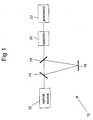
- FIG. 1 schematically shows a CEOS instrument 10, which, as indicated above, can be either a CRDS instrument or a CEAS instrument.
- a CEOS instrument normally includes at least the following components: a) an optical cavity containing two to four planar or curved mirrors (a three mirror cavity, with mirrors numbered 14, 16 and 18, is shown here); b) optical source 12, which is typically either a pulsed laser or a continuous wave laser(although as noted above source 12 can also be an incoherent source); c) mode matching optics 13 located between the laser and the optical cavity to mode match the laser to the cavity; d) detector or detector array 20, which receives radiation emitted by the cavity; e) transfer optics 19 located between the cavity and the detector to focus the light emitted from the cavity onto the detector; and f) processor 22, which processes the signal received by the detector to provide measurement results.
- a detector array is frequently appropriate when the light source is an incoherent source as opposed to a laser.
- Components a) through e) i.e. components 12 through 20 of Figure 1, are normally referred to as the optical train.
- the components of a CEOS instrument are typically positioned on support means which can be any substantially rigid planar surface (normally called an "optical bench” or “bread board” and not shown in this Figure).
- Such optical benches are preferably of high thermal mass and conductivity to help maintain the optical train at a stable and uniform temperature, and hence are normally fabricated at least principally of metal.
- the optical cavity (sometimes called the ring-down cavity or the resonant cavity) comprises a glass or metal tubular container for the sample, which can be a gas, a liquid or a vapor, e.g., a gas containing dispersed particulate matter and/or aerosol droplets, such as normal atmospheric air or stack gases. Additionally, the cavity will usually include sample inlet and outlet means.
- FIG 2a is schematic top view of an enclosure 30 according to the present invention having a CEOS instrument optical train 40 centrally located therein.
- No. 32 indicates the enclosure wall and No. 34 an inner insulating layer.
- enclosure wall 32 is illustrated as having an essentially rectangular configuration, which is generally the shape most easily fabricated, this is not a critical aspect of the invention.
- the enclosure can, for example, be of square, ovoid or other geometry. The important factor is that it be of a size and configuration to enable laminar gas flow and to permit the optical cavity, and preferably the complete optical train, of a CEOS instrument to be situated in a dead zone of the gas flow.
- Enclosure wall 32 is most conveniently fabricated of metal, although stiff plastic (e.g., Plexiglas or fiberglass reinforced epoxy) or a combination of metal and plastic may alternatively be used.
- Plastic has the advantage of being less thermally conductive than metal.
- at least a substantial portion of the surface of the inner and/or outer walls of the container will be covered with a low thermal conductivity insulating material, shown as No. 34 on the Figure. Most advantageously, this material will have both insulating and vibration damping characteristics, such as is provided by certain urethane foams.
- suitable foams include, for example, vinyl/nitrile copolymer closed cell foams.
- An additional or alternative insulating layer can be situated on the outer wall surface of enclosure wall 32.
- No. 36 shows the laminar flow of the gas (normally dry air) as it circulates within the enclosure.
- CEOS instrument optical train 40 is located within a "dead zone" encircled by laminar flow 36.
- the gas flow within the dead zone is generally not exactly zero, the gas flow speed within the dead zone is sufficiently low compared to the flow speed of laminar flow 36 that the gas in the dead zone can be regarded as being essentially static.
- the dead zone is not regarded as part of laminar flow 36, and so CEOS instrument optical train 40 is not within the path of laminar flow 36.
- No. 38 indicates the optical bench on which the components of CEOS instrument 40 are mounted.
- Optical bench 38 will normally be connected to an interior floor surface of enclosure 30 through a plurality of preferably vibration damping mounts which also provide thermal isolation between the bench and the floor of the enclosure.
- the fan is indicated as No. 42, and is mounted so as to circulate the gas present within the enclosure in a laminar flow 36 across heat exchanger 44 and substantially along some of the interior wall surfaces of the enclosure.
- the path of laminar flow 36 is substantially along four of the interior wall surfaces of enclosure 30, and is not substantially along the top or bottom of enclosure 30.
- Fan 42 is preferably an electric fan rotating at a relatively low speed.
- DC motors are preferable in fan 42 to AC motors, as DC motors permit facile control of the fan speed by merely raising or lowering the motor input voltage.
- DC motors tend to be less prone to vibration, especially at lower speeds.
- Heat exchanger 44 is normally a multi-finned metal structure mounted within the enclosure, in thermal communication with (and preferably affixed to) heat pump 46.
- Heat pump 46 is typically mounted to a wall of enclosure 30, and is in thermal communication with heat exchanger 44 and also with the ambient environment outside enclosure 30.
- heat pump 46 is shown as being situated in an aperture which passes through enclosure wall 32 and insulating layer 34.
- Heat pump 46 acts to transfer heat from the exterior to the interior of enclosure 30 (or in some circumstances vice versa). It is preferable for maximum flexibility for heat pump 46 to be a thermoelectric cooler/heater based on the Peltier Effect so that it can remove as well as add heat to the interior gas, although other mechanisms for transferring heat are also suitable for practicing the invention.
- heat pump encompass a resistance heater
- Heat pump 46 can be mounted on the inner or outer wall surface of enclosure 30, or may be mounted in a wall orifice so that the heat pump passes through the enclosure wall. The important factor is that heat pump 46 be in thermal communication with both the outside ambient air and also with the inside heat exchanger 44 so as to enable the heat exchanger to heat (or cool) the adjacent internal gas as may be necessary to accommodate any temperature change in the external environment.
- Temperature sensor 41 is optional, although it is present in a preferred embodiment of the invention. Temperature sensor 41 is preferably affixed to an exterior surface of the optical cavity of CEOS instrument optical train 40. An alternative arrangement, not shown on Figure 2a, is to affix temperature sensor 41 to optical bench 38. Under some circumstances it may be desirable to affix temperature sensors to both the optical cavity and the optical bench. Temperature sensor 41 is connected to an external control circuit which activates heat pump 46. Suitable temperature sensors include thermocouples, resistive thermal devices and preferably thermistors.
- the critical factor in providing accurate spectroscopic analysis is maintaining the optical cavity, and preferably the entire optical train, at a constant temperature.
- Such operations can be performed with a thermal controller (not shown on the Figure).
- a preferred approach is to use at least two thermistors (or other temperature sensors), one mounted on the optical cavity (i.e., temperature sensor 41) and a second on a heat exchanger (i.e., temperature sensor 43).
- the advantage of this approach may be more easily understood if we consider several factors that are normally present when the CEOS instrument is in operation: 1) the preferred operating temperature of the optical cavity, and preferably the entire optical train, will normally be higher than that of the ambient air outside the enclosure; 2) the thermal mass of the optical train and of the optical bench supporting same will be much greater than that of the heat exchanger; 3) the optical train and the optical bench will be at essentially the same temperature; 4) the optical train will generate some heat when in operation; and 5) there will be limited, but not zero, thermal communication from the outside ambient environment to the optical bench and train, for example, through the bench mounts.
- the enclosure and its contents i.e., optical bench, optical train, fans, heat exchangers and heat pump
- ambient temperature e.g. 25° C
- a desired operating temperature e.g. 40 °C
- the heat pump or pumps will input heat to the heat exchanger and the fan will cause laminar gas flow over the heat exchanger. Since the rate of heat transfer to the dead zone and thence to the bench and train is limited, and the thermal mass of the optical bench and train is high, bringing these components up to about 40°C will take some time.
- the optical train be at exactly 40°C (or some other selected operating temperature) but rather that its temperature not vary by more than ⁇ 0.01K, preferably not more than ⁇ 0.001K during an analysis.
- the thermal controller will recognize this temperature as a first set point and thereafter detect any change from temperature T1 by the optical train.
- the thermal controller will also recognize the temperature T2 of the heat exchanger (say 41°C), as indicated by temperature sensor 43, which is necessary to bring the optical bench and train to T1 and maintain them at Tlin the absence of a thermal change in the external environment.
- This heat exchanger temperature will be recognized by the controller as a second set point. Again the exact temperature of the second set point is not critical but rather that the temperature controller can determine whether to input or withdraw heat to move the temperature of the heat exchanger up or down from this set point as a result of even a very small change in T1. Since the temperature of the bench and train will only change slowly and to a very limited extent because of their thermal mass and location in the dead zone, as soon as any change from the first set point is detected (e.g.
- the controller will instruct the heat pump to raise the temperature of the heat exchanger above T2.
- the heat exchanger has low thermal mass and will heat rapidly and will likewise rapidly heat the circulating gas flowing over it, which will, even allowing for the limited heat transfer from the laminar flow gas to the dead zone gas, cause the temperature of the dead zone gas and hence of the optical bench and train to rise back to T1 before the bench and train have had the opportunity to fall below T1 to any significant extent, e.g., by more than 0.001° C.
- Figure 2b is a schematic side view of the same chamber as shown in Figure 2a and like numbers denote like components.
- Vertical support mounts 48 for the optical bench are shown on Figure 2b. These mounts serve to provide both thermal and vibrational insulation of optical bench 38 and CEOS instrument optical train 40 from environmental perturbations.
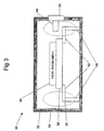
- FIG. 3 shows an alternative embodiment for the optical bench mounts.
- vertical support mounts 48 are not situated directly beneath bench 38. Rather, there are horizontal struts 50 which project outwardly from bench 38 to connect (or be integral) with support mounts 48.
- An advantage of this particular configuration is that it minimizes the effects of any heat transfer from the bench to the outside environment through the container walls at points 52 where the bench mounts contact the floor of the enclosure. This reduction in heat transfer is because the connection points of the bench to the supports are held at a temperature close to T1 by the circulating air, so there is no temperature difference to drive heat flow.
- An advantage of our enclosure design is that in order to affect the temperature of the optical train, a change in the ambient temperature outside the enclosure must be communicated through the enclosure walls, including through any insulating layers present thereon, and thence to the circulating gas (except for minimal transfer through the bench mounts). Since the dead zone gas surrounding the optical train is substantially static, any heat transfer to or from the dead zone can occur only be at the interface of the circulating laminar flow gas and the dead zone gas. Heat transfer to the optical train from the circulating gas can thus only be via conduction through the dead zone. Since gases are typically of low thermal conductivity, and since laminar flow is low friction flow relative to turbulent flow, the layers of circulating air between the walls and the dead zone can appropriately be thought of as providing "active insulation" to the optical train and bench. An additional benefit of our current enclosure design is that since any outside temperature change only impinges on the circulating gas, only a comparatively small portion of the gas within the enclosure (the circulating gas) needs to be directly heated (or cooled) by the heat pump.
Landscapes
- Physics & Mathematics (AREA)
- Spectroscopy & Molecular Physics (AREA)
- Health & Medical Sciences (AREA)
- Life Sciences & Earth Sciences (AREA)
- Chemical & Material Sciences (AREA)
- Analytical Chemistry (AREA)
- Biochemistry (AREA)
- General Health & Medical Sciences (AREA)
- General Physics & Mathematics (AREA)
- Immunology (AREA)
- Pathology (AREA)
- Investigating Or Analysing Materials By Optical Means (AREA)
Priority Applications (1)
| Application Number | Priority Date | Filing Date | Title |
|---|---|---|---|
| EP04256935A EP1655596A1 (fr) | 2004-11-09 | 2004-11-09 | Dispositif et méthode pour maintenir une température uniforme et stable pour la spectroscopie optique à cavité résonante |
Applications Claiming Priority (1)
| Application Number | Priority Date | Filing Date | Title |
|---|---|---|---|
| EP04256935A EP1655596A1 (fr) | 2004-11-09 | 2004-11-09 | Dispositif et méthode pour maintenir une température uniforme et stable pour la spectroscopie optique à cavité résonante |
Publications (1)
| Publication Number | Publication Date |
|---|---|
| EP1655596A1 true EP1655596A1 (fr) | 2006-05-10 |
Family
ID=34930783
Family Applications (1)
| Application Number | Title | Priority Date | Filing Date |
|---|---|---|---|
| EP04256935A Withdrawn EP1655596A1 (fr) | 2004-11-09 | 2004-11-09 | Dispositif et méthode pour maintenir une température uniforme et stable pour la spectroscopie optique à cavité résonante |
Country Status (1)
| Country | Link |
|---|---|
| EP (1) | EP1655596A1 (fr) |
Cited By (3)
| Publication number | Priority date | Publication date | Assignee | Title |
|---|---|---|---|---|
| ITRM20100571A1 (it) * | 2010-10-29 | 2012-04-30 | Auxilium Tech Srl | Sistema per la protezione dei dispositivi elettronici a temperatura di esercizio costante in ambienti con pericolo di esplosione in atmosfera. |
| WO2013010984A3 (fr) * | 2011-07-21 | 2013-09-19 | Universite De Reims Champagne Ardenne | Dispositif de détection de trace de gaz |
| CN116519873A (zh) * | 2023-02-01 | 2023-08-01 | 安徽岑锋科技有限公司 | 一种基于高稳定衰荡腔的温室气体测量装置 |
Citations (2)
| Publication number | Priority date | Publication date | Assignee | Title |
|---|---|---|---|---|
| GB1221419A (en) * | 1967-03-02 | 1971-02-03 | Perkin Elmer Ltd | Temperature control apparatus |
| US5692556A (en) * | 1994-01-14 | 1997-12-02 | Hafner; Erich | Precision temperature test chamber |
-
2004
- 2004-11-09 EP EP04256935A patent/EP1655596A1/fr not_active Withdrawn
Patent Citations (2)
| Publication number | Priority date | Publication date | Assignee | Title |
|---|---|---|---|---|
| GB1221419A (en) * | 1967-03-02 | 1971-02-03 | Perkin Elmer Ltd | Temperature control apparatus |
| US5692556A (en) * | 1994-01-14 | 1997-12-02 | Hafner; Erich | Precision temperature test chamber |
Cited By (5)
| Publication number | Priority date | Publication date | Assignee | Title |
|---|---|---|---|---|
| ITRM20100571A1 (it) * | 2010-10-29 | 2012-04-30 | Auxilium Tech Srl | Sistema per la protezione dei dispositivi elettronici a temperatura di esercizio costante in ambienti con pericolo di esplosione in atmosfera. |
| WO2012056391A3 (fr) * | 2010-10-29 | 2013-04-11 | Auxilium Tech S.R.L. | Système de protection pour des dispositifs électroniques à des températures de fonctionnement constantes dans des zones présentant un risque potentiel d'explosion dans l'atmosphère |
| WO2013010984A3 (fr) * | 2011-07-21 | 2013-09-19 | Universite De Reims Champagne Ardenne | Dispositif de détection de trace de gaz |
| CN116519873A (zh) * | 2023-02-01 | 2023-08-01 | 安徽岑锋科技有限公司 | 一种基于高稳定衰荡腔的温室气体测量装置 |
| CN116519873B (zh) * | 2023-02-01 | 2023-09-08 | 安徽岑锋科技有限公司 | 一种基于高稳定衰荡腔的温室气体测量装置 |
Similar Documents
| Publication | Publication Date | Title |
|---|---|---|
| US7050170B2 (en) | Apparatus and method for maintaining uniform and stable temperature for cavity enhanced optical spectroscopy | |
| Lacey et al. | Monitoring temperature changes in capillary electrophoresis with nanoliter-volume NMR thermometry | |
| Dubé et al. | Aircraft instrument for simultaneous, in situ measurement of NO3 and N2O5 via pulsed cavity ring-down spectroscopy | |
| Miklós et al. | Application of acoustic resonators in photoacoustic trace gas analysis and metrology | |
| CN102539019B (zh) | 空间真空环境下的温度测量与校准平台 | |
| US4180739A (en) | Thermostatable flow cell for fluorescence measurements | |
| EP2693194B1 (fr) | Procédé et dispositif d'analyse de gaz dissous | |
| EP1837645B1 (fr) | Capteur de conductivité thermique | |
| Gebhart et al. | Mixed convection from long horizontal cylinders | |
| JP7193466B2 (ja) | 複数温度光学分光計モジュール、システム、及びそれを使用する方法 | |
| EP1230553B1 (fr) | Analyseur chimique ou biochimique a regulation de la temperature reactionnelle | |
| JP2017504028A (ja) | 赤外吸収分光法を用いて試料ガス流中の少なくとも1つのガスの濃度を測定する装置 | |
| Ventrillard et al. | Accurate measurements and temperature dependence of the water vapor self-continuum absorption in the 2.1 μm atmospheric window | |
| EP1655596A1 (fr) | Dispositif et méthode pour maintenir une température uniforme et stable pour la spectroscopie optique à cavité résonante | |
| Merlone et al. | Design and capabilities of the temperature control system for the Italian experiment based on precision laser spectroscopy for a new determination of the Boltzmann constant | |
| RU2263305C1 (ru) | Динамический способ исследования теплофизических свойств жидкостей и устройство для исследования теплофизических свойств жидкостей | |
| JP2006138752A (ja) | 高性能キャビティを使用する分光法において均一且つ安定な温度を維持する装置及び方法 | |
| Stokka et al. | A simple system for automatic specific heat measurements | |
| US20050032233A1 (en) | Resonance-enhanced dielectric sensing of chemical and biological species | |
| JP2010276366A (ja) | 反応速度測定装置 | |
| Jaszczur et al. | Application of Laser Induced Fluorescence in experimental analysis of convection phenomena | |
| Adler | A hot wire technique for continuous measurement in unsteady concentration fields of binary gaseous mixtures | |
| Elder | [2] Density measurements by the mechanical oscillator | |
| Allen et al. | Measurement of the rates of fast reactions at temperatures down to–120° C | |
| Wachtor et al. | Buoyancy driven mixing of miscible fluids by volumetric energy deposition of microwaves |
Legal Events
| Date | Code | Title | Description |
|---|---|---|---|
| PUAI | Public reference made under article 153(3) epc to a published international application that has entered the european phase |
Free format text: ORIGINAL CODE: 0009012 |
|
| AK | Designated contracting states |
Kind code of ref document: A1 Designated state(s): AT BE BG CH CY CZ DE DK EE ES FI FR GB GR HU IE IS IT LI LU MC NL PL PT RO SE SI SK TR |
|
| AX | Request for extension of the european patent |
Extension state: AL HR LT LV MK YU |
|
| AKX | Designation fees paid | ||
| REG | Reference to a national code |
Ref country code: DE Ref legal event code: 8566 |
|
| STAA | Information on the status of an ep patent application or granted ep patent |
Free format text: STATUS: THE APPLICATION IS DEEMED TO BE WITHDRAWN |
|
| 18D | Application deemed to be withdrawn |
Effective date: 20061111 |