EP1655600A2 - Détecteur de fil - Google Patents
Détecteur de fil Download PDFInfo
- Publication number
- EP1655600A2 EP1655600A2 EP05022480A EP05022480A EP1655600A2 EP 1655600 A2 EP1655600 A2 EP 1655600A2 EP 05022480 A EP05022480 A EP 05022480A EP 05022480 A EP05022480 A EP 05022480A EP 1655600 A2 EP1655600 A2 EP 1655600A2
- Authority
- EP
- European Patent Office
- Prior art keywords
- light
- yarn
- lens
- light source
- yarn sensor
- Prior art date
- Legal status (The legal status is an assumption and is not a legal conclusion. Google has not performed a legal analysis and makes no representation as to the accuracy of the status listed.)
- Granted
Links
Images


Classifications
-
- G—PHYSICS
- G01—MEASURING; TESTING
- G01N—INVESTIGATING OR ANALYSING MATERIALS BY DETERMINING THEIR CHEMICAL OR PHYSICAL PROPERTIES
- G01N21/00—Investigating or analysing materials by the use of optical means, i.e. using sub-millimetre waves, infrared, visible or ultraviolet light
- G01N21/84—Systems specially adapted for particular applications
- G01N21/88—Investigating the presence of flaws or contamination
- G01N21/89—Investigating the presence of flaws or contamination in moving material, e.g. running paper or textiles
- G01N21/8914—Investigating the presence of flaws or contamination in moving material, e.g. running paper or textiles characterised by the material examined
- G01N21/8915—Investigating the presence of flaws or contamination in moving material, e.g. running paper or textiles characterised by the material examined non-woven textile material
-
- G—PHYSICS
- G01—MEASURING; TESTING
- G01N—INVESTIGATING OR ANALYSING MATERIALS BY DETERMINING THEIR CHEMICAL OR PHYSICAL PROPERTIES
- G01N33/00—Investigating or analysing materials by specific methods not covered by groups G01N1/00 - G01N31/00
- G01N33/36—Textiles
- G01N33/365—Filiform textiles, e.g. yarns
Definitions
- the invention relates to a yarn sensor for optically scanning a yarn moved in its longitudinal direction in a measuring nip according to the preamble of claim 1.
- Optical systems are simple in construction and function as well as inexpensive to carry out. They work with shading or reflected light.
- the test material is illuminated by a light source.
- the generic EP 0 761 585 A1 describes a yarn sensor with an optically operating system, which can also serve in addition to the determination of the yarn diameter for the detection of foreign material in the yarn, such as foreign fibers or impurities.
- the surfaces in the measurement gap which are struck by light emitted by the light source, reflect this incident light.
- the light reflected from the yarn is a relatively small signal source due to the small surface area of the yarn.
- the yarn signal converted into current moves in the nanoampere range. Because of their extent, the surface of the measurement gap, which has a relatively large surface area and is contaminated with dirt, constitutes a considerable reflection signal source.
- the interference radiation that falsifies the measurement result is also called a parasitic signal.
- CH 643 060 also describes an optical system for testing the yarn diameter.
- a measurement signal proportional to the diameter of the yarn is generated. Signal fluctuations caused by changes in the light intensity of the light source as a result of fluctuations in the supply voltage, aging or turbidity are compensated by means of circuitry.
- a light cone is emitted by a point light source in the direction of an image recorder and the yarn passing between the light source and the image recorder is imaged on the image recorder as a shadow.
- the image sensor is a CCD line sensor. The extent of shading on the image sensor depends on the diameter of the yarn.
- the location of the yarn significantly affects the size of the shaded area. If, for example, the yarn moves towards the image recorder with the yarn diameter remaining the same, the shading becomes smaller, although the yarn diameter has remained the same. This leads to distortions of the measurement result.
- CH 643 060 there is an optical system between the light source and the yarn, which is designated as a punctiform point, which is intended to project light emitted by the light source as an approximately parallel beam onto the image sensor.
- a punctiform point which is intended to project light emitted by the light source as an approximately parallel beam onto the image sensor.
- the light is usually generated in light bulbs by means of a salient filament. Since the requirement of a punctiform light source can not be met, the evenly distributed illuminance and the parallelism of the beam directed onto the image sensor can not be achieved and remain deficient. An independent of the position of the yarn in the measuring gap measurement result is not achievable with the device of CH 643 060.
- Another possibility to generate parallel light is to convert the light emitted by a Lambertian radiator.
- the luminance of a Lambertian radiator is constant in all directions of the half-space defined above the light-emitting surface.
- the Lambert radiator thus behaves like an ideal diffusely radiating surface.
- Such surface radiators are, for example, fluorescent lamps, but because of the required size they are not suitable for use in yarn measuring heads at the workstations of a spinning or winding machine.
- LEDs are also surface radiators and are usually provided with the attribute of exhibiting a Lambertian radiation characteristic. Loud Definition is the radiation emitted by each point of the surface of a Lambertian radiator as a divergent light beam.
- DE 23 37 413 B2 and DE 198 59 274 A1 show devices for monitoring a running yarn, in which light emitting diodes are used as light sources and photodiodes as the light receiver.
- the invention is based on the finding that the light sources expressly referred to as Lambertian radiators for use in a yarn cleaner show only insufficient behavior to a lambertian radiator behavior. This occurs due to structural tolerances in the production and inaccuracies of positioning during assembly.
- These working with light emitting diodes emit a light beam, which is not rotationally symmetrical to the optical axis of the existing light source, lens and receiver system is formed.
- the asymmetrical radiation (“squint”) changes from one LED to the next.
- the inventive design of the yarn sensor makes it possible that the sampled yarn moves in the measuring gap in a light beam, which consists of a very homogeneous in its illuminance radiation and parallel to each other and parallel to the optical axis extending light beams.
- a considerably improved independence of the measurement result from the position of the yarn in the measuring gap is achieved compared with the prior art. Loss of light caused by stray light, which weakens the measuring signals, is minimized.
- the light source is a light emitting diode.
- Light-emitting diodes require little space and are therefore particularly well suited for use in jobs of spinning or winding machines, where there is only very limited space available.
- the light-emitting diode is preferably designed as a white light LED.
- the color spectrum of the white light diode offers all possibilities in color detection. Inexpensive can be dispensed with the use of additional LEDs with light in other colors and the required space can be kept low. Since a white light emitting diode serving as a sole light source emits light in all required colors, a consistent sensitivity of the yarn sensor to different colors is made possible. A single white light diode comes much closer to a point light source model than an array of two or more light emitting diodes.
- a designed as a film according to claim 4 diffuser emits such a diffused light that this is a suitable basis for the formation of a light beam by means of a lens according to claim 5.
- diffuser can be used a film of the type Oracal 8005, series Translucent, the company K. Gröner. This film has hitherto been used for advertising stickers and thus in a field of application which is completely different from a use in a yarn sensor for increasing the measuring accuracy as in the present invention.
- the light bundle advantageously has a homogeneously distributed illuminance and a beam path which is quasi-parallel to the optical axis of the lens, with the entire beam having a divergence approaching zero.
- a punctiform spot for example due to contamination, does not lead to the inhomogeneity of the light beam in the measuring field, as long as the remaining luminous film radiates light that meets the requirements of the Lambertian radiation characteristic.
- a diaphragm according to claim 8 contributes to the fact that only light of the light source passes into the measuring gap, which is homogeneously distributed and aligned parallel to the optical axis of the arranged in front of the light source lens.
- An aperture after Claim 9 limits the light beam directed onto the yarn such that only surfaces are illuminated which do not cause reflections which lead to parasitic signals.
- the quality of the measurement result is improved in the determination of the yarn diameter and in the detection of foreign fibers.
- a better homogeneity of the light beam is achieved. Therefore, a wider field of view is possible while improving homogeneity in the measurement field.
- the result is that a larger thread movement tolerated in the measuring field and can be dispensed with thread guide for guiding the yarn in the measuring gap, if necessary. In this way, constructional effort can be saved and the thread is less damaged. The contamination in the area of the yarn sensor due to abrasion is reduced.
- the yarn 3 produced in the spin box 1 is withdrawn via the withdrawal tube 4 by means of the withdrawal roller pair 5, passes through a yarn sensor 6 and is wound over a bracket 8 by the reciprocation of the yarn guide 9 a traversing device 7 over a predetermined width to a cross-wound bobbin 10 ,
- the cross-wound bobbin 10 is driven by means of a friction roller 11.
- the yarn guide 9 is mounted on a yarn guide rod 12 which is reciprocated by a yarn guide gear 13.
- the drive of the thread guide transmission 13 is effected by a drive device 14.
- the yarn sensor 6 for monitoring the running yarn 3 is arranged above the take-off roller pair 5 in the traversing region of the yarn 3.
- the yarn sensor 6 upstream of the take-off roller 5 may be arranged downstream instead.
- the yarn sensor 6 is connected via a line 15 to the control device 16 which receives the signals emitted by the yarn sensor 6. Via a further line 17, the control device 16 is connected to the drive device 14.
- the drive device 14 is designed as an electric motor. Via the line 18, the control device 16 is connected to other spinning stations, data processing equipment or spinning machines not shown here.
- the position of individual components of the yarn sensor 6 to the measuring gap 19 and the yarn 3 can be removed.
- the formed as a light emitting diode 20 light source and the photodiodes 21, 22, which reflected the reception of the yarn 3 Serving light are positioned in the illustration of FIG. 2 to the right of the measuring gap 19.
- the photodiode 23 for receiving the light transmitted directly from the light-emitting diode 20 is positioned to the left of the measuring gap 19 in the illustration of FIG. 2.
- 25, 26, 27 are arranged for transmitting the light.
- the elements 24, 25, 26, 27 for transmitting the light are separated from the measuring gap 19 by windows 28, 29, 30, 31.
- the windows may provide protection to the elements 24, 25, 26, 27 for transmitting the light from dust and fiber fly contamination.
- the light-emitting diode 20 and the photodiodes 21, 22, 23 are each connected to a signal processing device 36 by means of the lines 32, 33, 34, 35.
- the signal processing device 36 in turn is connected to the control device 16 via the line 15, which leads through the housing 37 of the yarn sensor 6 to the outside.
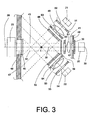
- Fig. 3 shows an arrangement of components of the yarn sensor 6, which is suitable for detecting foreign substances in the yarn 3.
- the light source is the light-emitting diode 20, which has approximately the emission characteristic of a Lambertian radiator.
- the light-emitting diode 20 is designed as a white light emitting diode.
- White light LEDs emit light with a broad emission spectrum.
- the use of a plurality of light emitting diodes for emitting different colors or for amplifying the emitted light can be dispensed with when using a white light LED.
- the abbreviation "LED" is commonly used.
- the light emitted from the light emitting diode 20 passes through the element 24 for transmitting the light.
- the element 24 comprises a foil 39, a shutter 40 with the aperture 41, a lens 42, a shutter 60 with rectangular aperture 61 and a glass plate 59, which are successively traversed by the light in the direction of the optical axis 38.
- the aperture 40 has an aperture 41 with a width of 1 mm.
- the film 39 emits divergent light bundles and has the emission characteristic of a Lambertian radiator.
- a film 39 for example, the film type Oracal 8500, series Translucent, the company. K. Gröner is used.
- the individual light beams are aligned quasi-parallel to each other in the direction of the optical axis 38 and distributed homogeneously over the cross section of the total light beam.
- the total light beam is represented by the two dashed lines 43, 44.
- the film 39 forms a virtual light source, which is imaged at infinity. On the way of the light beam between lens 42 and the image plane of the photodiode 23, the image of the virtual light source is always present. The image is out of focus. This effect is accompanied by a further homogenization of the light beam.
- the yarn 3 traverses the course of the total light beam and is imaged in the form of shading on the photodiode 23. Between the yarn 3 and the photodiode 23, the total light beam passes through the glass pane 45 and the aperture 46 of the aperture 47. The yarn 3 reflects light emitted by the light-emitting diode 20.
- the photodiodes 21, 22 detect a part of the reflected light. Between the yarn 3 and the photodiodes 21, 22, the reflected light passes through the elements 25, 26, respectively.
- the elements 25, 26 each comprise the associated glass pane 48, 52, the aperture 63, 64, the lens 49, 53 and the aperture 50, 54 of the aperture 51, 55.
- the elements 25, 26 for transmitting the reflected light are formed and arranged that by the photodiodes 21, 22 in the absence of the yarn 3 in each case images of the opposite surfaces, for example, the diaphragm 40 or the wall 62 of the measuring gap 19, are detectable. These surfaces lie on both sides outside of the illuminated by the direct radiation of the light emitting diode 20 surface of the wall 62 of the measuring gap 19th
- the apertures 51 and 55 may be omitted.
- the glass sheets 48, 52, 59 may be formed in a further alternative embodiment as diaphragms and have rectangular apertures.
- FIG. 4 shows the basic illustration of the light-emitting diode 20 whose light-radiating surface 56 has the characteristic of a Lambertian radiator. From each point 57 of the surface 56 a divergent beam 58 is emitted.
- the light that emits a Lambertian radiator can be converted into a homogeneous light with quasiparallelem beam path, the homogeneity and the parallelism of the light are better than it is the case when conventional so-called point light sources are used.
Landscapes
- Engineering & Computer Science (AREA)
- Textile Engineering (AREA)
- Chemical & Material Sciences (AREA)
- Health & Medical Sciences (AREA)
- Life Sciences & Earth Sciences (AREA)
- General Health & Medical Sciences (AREA)
- Analytical Chemistry (AREA)
- Biochemistry (AREA)
- Physics & Mathematics (AREA)
- General Physics & Mathematics (AREA)
- Immunology (AREA)
- Pathology (AREA)
- Food Science & Technology (AREA)
- Medicinal Chemistry (AREA)
- Length Measuring Devices By Optical Means (AREA)
- Investigating Materials By The Use Of Optical Means Adapted For Particular Applications (AREA)
- Investigating Or Analysing Materials By Optical Means (AREA)
Applications Claiming Priority (1)
| Application Number | Priority Date | Filing Date | Title |
|---|---|---|---|
| DE102004053736A DE102004053736B4 (de) | 2004-11-06 | 2004-11-06 | Garnsensor |
Publications (3)
| Publication Number | Publication Date |
|---|---|
| EP1655600A2 true EP1655600A2 (fr) | 2006-05-10 |
| EP1655600A3 EP1655600A3 (fr) | 2006-06-28 |
| EP1655600B1 EP1655600B1 (fr) | 2012-09-26 |
Family
ID=35663361
Family Applications (1)
| Application Number | Title | Priority Date | Filing Date |
|---|---|---|---|
| EP05022480A Expired - Lifetime EP1655600B1 (fr) | 2004-11-06 | 2005-10-14 | Détecteur de fil |
Country Status (4)
| Country | Link |
|---|---|
| US (1) | US7333202B2 (fr) |
| EP (1) | EP1655600B1 (fr) |
| CN (1) | CN1769890B (fr) |
| DE (1) | DE102004053736B4 (fr) |
Cited By (1)
| Publication number | Priority date | Publication date | Assignee | Title |
|---|---|---|---|---|
| WO2011026249A1 (fr) | 2009-09-07 | 2011-03-10 | Uster Technologies Ag | Dispositif et procédé pour réaliser le balayage optique d'un textile en mouvement |
Families Citing this family (24)
| Publication number | Priority date | Publication date | Assignee | Title |
|---|---|---|---|---|
| JP4533737B2 (ja) * | 2004-02-03 | 2010-09-01 | 株式会社島精機製作所 | 糸画像作成装置と糸画像作成方法、並びに糸画像作成プログラム |
| EP1645241B1 (fr) * | 2004-10-05 | 2011-12-28 | BrainLAB AG | Système de marque de position avec des sources lumineuses ponctuelles |
| DE102004053735A1 (de) * | 2004-11-06 | 2006-05-11 | Saurer Gmbh & Co. Kg | Garnsensor |
| DE102007056562A1 (de) * | 2007-11-23 | 2009-05-28 | Oerlikon Textile Gmbh & Co. Kg | Vorrichtung zur optischen Detektion von Verunreinigungen in längsbewegtem Garn |
| DE102008017258A1 (de) * | 2008-04-04 | 2009-10-08 | Oerlikon Textile Gmbh & Co. Kg | Verfahren und Vorrichtung zur optischen Detektion von Fremdfasern in einem längs bewegtem Faserstrang |
| EP2175058B1 (fr) * | 2008-10-10 | 2011-08-03 | Gebrüder Loepfe AG | Métier à tisser doté d'un capteur de qualité de fil |
| CZ305932B6 (cs) * | 2009-09-30 | 2016-05-11 | Rieter Cz S.R.O. | Způsob sledování barevné homogenity povrchu příze a zařízení k jeho provádění |
| CZ2010423A3 (cs) * | 2010-05-28 | 2010-08-18 | Perner@Petr | Metoda, zpusob a zarízení ke kontinuálnímu zjištování tlouštky a/nebo homogenity lineárního útvaru, zejména textilního vlákna |
| CZ304010B6 (cs) | 2012-10-02 | 2013-08-14 | Rieter Cz S.R.O. | Zarízení pro sledování kvality pohybujícího se lineárního textilního materiálu, zejména príze |
| CZ2013450A3 (cs) * | 2013-06-12 | 2014-02-12 | Rieter Cz S.R.O. | Způsob a zařízení ke sledování lineárního útvaru |
| CZ305265B6 (cs) | 2013-12-17 | 2015-07-08 | Rieter Cz S.R.O. | Způsob sledování kvality příze nebo jiného lineárního textilního útvaru v optickém snímači kvality příze a řádkový optický snímač k provádění způsobu |
| EP2907907B1 (fr) * | 2014-02-13 | 2017-05-03 | L.G.L. Electronics S.p.A. | Dispositif d'alimentation de fil de stockage avec tambour rotatif et capteur de déroulement du fil |
| CN103981607B (zh) * | 2014-05-23 | 2016-08-17 | 汪建建 | 一种螺旋光电清纱器 |
| DE102014112323A1 (de) * | 2014-08-27 | 2016-03-03 | Frank Braun | Messung der zukünftigen Färbeeigenschaften bei Spinnfäden |
| ITPO20150002A1 (it) * | 2015-02-06 | 2016-08-06 | Ecafil Best Spa Ind Filati | Sistema e metodo di controllo e programmazione della produzione di un gomitolo |
| WO2017168236A1 (fr) * | 2016-04-01 | 2017-10-05 | Schleuniger Holding Ag | Capteur combiné |
| US10084997B1 (en) * | 2017-05-23 | 2018-09-25 | Sony Corporation | Adaptive optics for a video projector |
| US10605798B2 (en) * | 2017-12-26 | 2020-03-31 | Petr PERNER | Method and device for optical yarn quality monitoring |
| CZ201875A3 (cs) * | 2018-02-15 | 2019-08-28 | Rieter Cz S.R.O. | Zařízení pro bezkontaktní měření parametrů lineárního textilního útvaru, způsob jeho řízení a textilní stroj |
| DE102018111648A1 (de) * | 2018-05-15 | 2019-11-21 | Saurer Spinning Solutions Gmbh & Co. Kg | Garnsensor zum optischen Erfassen eines in seiner Längsrichtung bewegten Garns |
| CN109056200A (zh) * | 2018-09-04 | 2018-12-21 | 福恩达机器人(昆山)有限公司 | 一种缝纫机的布料边界识别方法和传感器及其识别装置 |
| EP3748285A1 (fr) | 2019-06-06 | 2020-12-09 | Gebrüder Loepfe AG | Capteur optique pour mesurer une propriété d'un corps textile allongé présentant une sensibilité réduite à l'éclairage ambiant |
| EP3748343B1 (fr) * | 2019-06-06 | 2022-08-17 | Gebrüder Loepfe AG | Dispositif de capteur optique pour la détection de matériau étranger dans un corps textile allongé |
| CN117470803B (zh) * | 2023-10-30 | 2024-04-26 | 无锡迅杰光远科技有限公司 | 筒纱用的手持式近红外检测设备及检测方法 |
Citations (6)
| Publication number | Priority date | Publication date | Assignee | Title |
|---|---|---|---|---|
| DE2337413B2 (de) | 1972-10-16 | 1979-01-04 | Gebrueder Loepfe Ag, Wetzikon (Schweiz) | Optoelektrische Messeinrichtung zur Messung der Querdimensionen von laufenden Fäden |
| CH643060A5 (de) | 1979-11-20 | 1984-05-15 | Zellweger Uster Ag | Verfahren zur bestimmung des durchmessers oder des querschnittes eines faden- oder drahtfoermigen koerpers, vorrichtung zur ausfuehrung des verfahrens, sowie anwendung des verfahrens. |
| EP0244788A2 (fr) | 1986-05-07 | 1987-11-11 | Zellweger Uster Ag | Dispositif de mesure de la coupe en travers ou du volume d'un fil courant |
| WO1993013407A1 (fr) | 1991-12-20 | 1993-07-08 | Siegfried Peyer Ag | Detection de fibres etrangeres dans des fils |
| EP0761585A1 (fr) | 1995-09-06 | 1997-03-12 | Zellweger Luwa Ag | Détecteur de fil |
| DE19859274A1 (de) | 1998-12-22 | 2000-06-29 | Schlafhorst & Co W | Vorrichtung zur Erkennung von Fremdstoffen in strangförmigen textilen Material |
Family Cites Families (13)
| Publication number | Priority date | Publication date | Assignee | Title |
|---|---|---|---|---|
| DE3681481D1 (de) * | 1985-04-04 | 1991-10-24 | Commw Scient Ind Res Org | Ueberwachung von verunreinigungen in textilerzeugnissen. |
| EP0227861B1 (fr) * | 1985-12-24 | 1990-07-04 | Barco Automation, Naamloze Vennootschap | Procédé de mesure d'une grandeur physique fournissant des données numériques à partir de dispositifs de mesure de valeurs analogiques et appareil de mesure appliquant ce procédé |
| CH683294A5 (de) * | 1992-01-31 | 1994-02-15 | Loepfe Ag Geb | Vorrichtung zur Detektion von Verunreinigungen, insbesondere Fremdfasern in einem langgestreckten, textilen Gebilde. |
| CH683378A5 (de) | 1992-03-17 | 1994-02-28 | Zellweger Uster Ag | Verfahren und Vorrichtung zur Detektion von Verunreinigungen in einem textilen Prüfgut sowie Verwendung der Vorrichtung. |
| CH686803A5 (de) * | 1993-09-09 | 1996-06-28 | Luwa Ag Zellweger | Verfahren und Vorrichtung zur Detektion von Fremdstoffen in einem textilen Pruefgut. |
| JP3611140B2 (ja) * | 1995-07-20 | 2005-01-19 | 計測器工業株式会社 | 糸の測定装置 |
| DE19939711B4 (de) * | 1999-08-21 | 2015-03-12 | Saurer Germany Gmbh & Co. Kg | Verfahren und Vorrichtung zur Detektierung von Fremdkörpern in einem längsbewegten Faden |
| EP1117990A1 (fr) * | 1998-10-01 | 2001-07-25 | Zellweger Luwa Ag | Dispositif de detection de substances etrangeres dans un fil |
| DE19909703A1 (de) * | 1999-03-05 | 2000-09-07 | Schlafhorst & Co W | Vorrichtung zur optischen Garnüberwachung |
| DE10009131A1 (de) * | 2000-02-26 | 2001-08-30 | Schlafhorst & Co W | Verfahren und Vorrichtung zur optischen Detektion von Verunreinigungen, insbesondere Fremdfasern, in längsbewegten Garn |
| US7333203B2 (en) * | 2002-11-13 | 2008-02-19 | Uster Technologies Ag | Device for scanning a yarn with a light beam |
| JP4261285B2 (ja) * | 2003-08-21 | 2009-04-30 | 村田機械株式会社 | 糸の異物検出装置 |
| DE102004002047A1 (de) * | 2004-01-15 | 2005-08-04 | Saurer Gmbh & Co. Kg | Verfahren und Vorrichtung zur optischen Überwachung eines laufenden Faserstranges |
-
2004
- 2004-11-06 DE DE102004053736A patent/DE102004053736B4/de not_active Expired - Fee Related
-
2005
- 2005-09-01 CN CN200510093974.XA patent/CN1769890B/zh not_active Expired - Fee Related
- 2005-10-07 US US11/245,771 patent/US7333202B2/en not_active Expired - Lifetime
- 2005-10-14 EP EP05022480A patent/EP1655600B1/fr not_active Expired - Lifetime
Patent Citations (6)
| Publication number | Priority date | Publication date | Assignee | Title |
|---|---|---|---|---|
| DE2337413B2 (de) | 1972-10-16 | 1979-01-04 | Gebrueder Loepfe Ag, Wetzikon (Schweiz) | Optoelektrische Messeinrichtung zur Messung der Querdimensionen von laufenden Fäden |
| CH643060A5 (de) | 1979-11-20 | 1984-05-15 | Zellweger Uster Ag | Verfahren zur bestimmung des durchmessers oder des querschnittes eines faden- oder drahtfoermigen koerpers, vorrichtung zur ausfuehrung des verfahrens, sowie anwendung des verfahrens. |
| EP0244788A2 (fr) | 1986-05-07 | 1987-11-11 | Zellweger Uster Ag | Dispositif de mesure de la coupe en travers ou du volume d'un fil courant |
| WO1993013407A1 (fr) | 1991-12-20 | 1993-07-08 | Siegfried Peyer Ag | Detection de fibres etrangeres dans des fils |
| EP0761585A1 (fr) | 1995-09-06 | 1997-03-12 | Zellweger Luwa Ag | Détecteur de fil |
| DE19859274A1 (de) | 1998-12-22 | 2000-06-29 | Schlafhorst & Co W | Vorrichtung zur Erkennung von Fremdstoffen in strangförmigen textilen Material |
Cited By (1)
| Publication number | Priority date | Publication date | Assignee | Title |
|---|---|---|---|---|
| WO2011026249A1 (fr) | 2009-09-07 | 2011-03-10 | Uster Technologies Ag | Dispositif et procédé pour réaliser le balayage optique d'un textile en mouvement |
Also Published As
| Publication number | Publication date |
|---|---|
| EP1655600B1 (fr) | 2012-09-26 |
| DE102004053736B4 (de) | 2013-05-29 |
| US7333202B2 (en) | 2008-02-19 |
| EP1655600A3 (fr) | 2006-06-28 |
| DE102004053736A1 (de) | 2006-05-11 |
| CN1769890A (zh) | 2006-05-10 |
| US20060098201A1 (en) | 2006-05-11 |
| CN1769890B (zh) | 2010-11-03 |
Similar Documents
| Publication | Publication Date | Title |
|---|---|---|
| EP1655600B1 (fr) | Détecteur de fil | |
| EP1655599B1 (fr) | Détecteur de fil | |
| EP0279191B1 (fr) | Dispositif pour la mesure sans contact de la rémission | |
| EP2475978B1 (fr) | Dispositif et procédé pour réaliser le balayage optique d'un textile en mouvement | |
| WO1993013407A1 (fr) | Detection de fibres etrangeres dans des fils | |
| DE3437580A1 (de) | Vorrichtung zum optischen pruefen eines zigarettenstrangs | |
| EP0652432A1 (fr) | Dispositif de détection des impuretés, notamment des fibres étrangères dans des textiles en mouvement | |
| EP0762174B1 (fr) | Dispositif d'éclairage linéaire de matériaux sous forme de feuilles comme par exemple des billets de banque ou papiers de valeur | |
| DE4444079C2 (de) | Verfahren und Vorrichtung zur Durchführung dieses Verfahrens zum Messen der Lage einer Kante von einer Bahn oder einem Bogen | |
| DE202005007089U1 (de) | Sensoranordnung zur optischen Kantendetektierung einer Ware | |
| EP0281747A2 (fr) | Rideau de lumière | |
| DE19506467A1 (de) | Vorrichtung und Verfahren zum Messen einer Lage einer Kante von Bahnen oder Bogen | |
| EP2929329B1 (fr) | Dispositif pour le contrôle optique d'un textile en mouvement | |
| DE3108344A1 (de) | Laserinspektionssystem | |
| WO2001050735A1 (fr) | Systeme d'appareil photographique pour le traitement de documents | |
| DE1798349A1 (de) | Verfahren,Vorrichtung und Einrichtung zum Auffinden und Klassieren von Fehlern in einem Band oder einem Schleier von Textilfasern | |
| DE69113797T2 (de) | Fadenliefervorrichtung. | |
| EP2253948A1 (fr) | Dispositif d'examen optique d'un objet | |
| EP0417042B1 (fr) | Dispositif de balayage photo-électrique | |
| DE102018131264A1 (de) | Spulmaschine sowie Vorrichtung zur Erkennung von Fadenresten | |
| DE3834478A1 (de) | Verfahren zur messung der anzahl von titerungleichmaessigkeiten sowie vorrichtung zur durchfuehrung des verfahrens | |
| DE69106683T2 (de) | Vorrichtung zur Detektion von Unregelmässigkeiten des Durchmessers eines Fadens. | |
| EP1859227B1 (fr) | Systeme de capteurs destine a la detection d'arete optique d'un produit et procede de determination de largeur | |
| DE2816986C3 (de) | Anordnung zum Aufsuchen von Fehlern auf laufenden Bändern | |
| CH502596A (de) | Vorrichtung zum Feststellen von Streifen auf einer laufenden Bahn bei der Herstellung von Fotopapieren und -filmen |
Legal Events
| Date | Code | Title | Description |
|---|---|---|---|
| PUAI | Public reference made under article 153(3) epc to a published international application that has entered the european phase |
Free format text: ORIGINAL CODE: 0009012 |
|
| AK | Designated contracting states |
Kind code of ref document: A2 Designated state(s): AT BE BG CH CY CZ DE DK EE ES FI FR GB GR HU IE IS IT LI LT LU LV MC NL PL PT RO SE SI SK TR |
|
| AX | Request for extension of the european patent |
Extension state: AL BA HR MK YU |
|
| PUAL | Search report despatched |
Free format text: ORIGINAL CODE: 0009013 |
|
| AK | Designated contracting states |
Kind code of ref document: A3 Designated state(s): AT BE BG CH CY CZ DE DK EE ES FI FR GB GR HU IE IS IT LI LT LU LV MC NL PL PT RO SE SI SK TR |
|
| AX | Request for extension of the european patent |
Extension state: AL BA HR MK YU |
|
| 17P | Request for examination filed |
Effective date: 20061228 |
|
| AKX | Designation fees paid |
Designated state(s): BE CH DE LI |
|
| RAP1 | Party data changed (applicant data changed or rights of an application transferred) |
Owner name: OERLIKON TEXTILE GMBH & CO. KG |
|
| RAP1 | Party data changed (applicant data changed or rights of an application transferred) |
Owner name: OERLIKON TEXTILE GMBH & CO. KG |
|
| 17Q | First examination report despatched |
Effective date: 20110920 |
|
| GRAP | Despatch of communication of intention to grant a patent |
Free format text: ORIGINAL CODE: EPIDOSNIGR1 |
|
| GRAS | Grant fee paid |
Free format text: ORIGINAL CODE: EPIDOSNIGR3 |
|
| GRAA | (expected) grant |
Free format text: ORIGINAL CODE: 0009210 |
|
| AK | Designated contracting states |
Kind code of ref document: B1 Designated state(s): BE CH DE LI |
|
| REG | Reference to a national code |
Ref country code: CH Ref legal event code: EP |
|
| REG | Reference to a national code |
Ref country code: DE Ref legal event code: R096 Ref document number: 502005013125 Country of ref document: DE Effective date: 20121122 |
|
| BERE | Be: lapsed |
Owner name: OERLIKON TEXTILE G.M.B.H. & CO. KG Effective date: 20121031 |
|
| PG25 | Lapsed in a contracting state [announced via postgrant information from national office to epo] |
Ref country code: BE Free format text: LAPSE BECAUSE OF NON-PAYMENT OF DUE FEES Effective date: 20121031 |
|
| PLBE | No opposition filed within time limit |
Free format text: ORIGINAL CODE: 0009261 |
|
| STAA | Information on the status of an ep patent application or granted ep patent |
Free format text: STATUS: NO OPPOSITION FILED WITHIN TIME LIMIT |
|
| 26N | No opposition filed |
Effective date: 20130627 |
|
| REG | Reference to a national code |
Ref country code: DE Ref legal event code: R097 Ref document number: 502005013125 Country of ref document: DE Effective date: 20130627 |
|
| REG | Reference to a national code |
Ref country code: DE Ref legal event code: R081 Ref document number: 502005013125 Country of ref document: DE Owner name: SAURER GERMANY GMBH & CO. KG, DE Free format text: FORMER OWNER: SAURER GMBH & CO. KG, 41069 MOENCHENGLADBACH, DE Effective date: 20120926 Ref country code: DE Ref legal event code: R081 Ref document number: 502005013125 Country of ref document: DE Owner name: SAURER GERMANY GMBH & CO. KG, DE Free format text: FORMER OWNER: OERLIKON TEXTILE GMBH & CO. KG, 42897 REMSCHEID, DE Effective date: 20130918 Ref country code: DE Ref legal event code: R081 Ref document number: 502005013125 Country of ref document: DE Owner name: SAURER SPINNING SOLUTIONS GMBH & CO. KG, DE Free format text: FORMER OWNER: SAURER GMBH & CO. KG, 41069 MOENCHENGLADBACH, DE Effective date: 20120926 Ref country code: DE Ref legal event code: R081 Ref document number: 502005013125 Country of ref document: DE Owner name: SAURER SPINNING SOLUTIONS GMBH & CO. KG, DE Free format text: FORMER OWNER: OERLIKON TEXTILE GMBH & CO. KG, 42897 REMSCHEID, DE Effective date: 20130918 |
|
| REG | Reference to a national code |
Ref country code: CH Ref legal event code: PUE Owner name: SAURER GERMANY GMBH AND CO. KG, DE Free format text: FORMER OWNER: OERLIKON TEXTILE GMBH AND CO. KG, DE Ref country code: CH Ref legal event code: NV Representative=s name: SCHMAUDER AND PARTNER AG PATENT- UND MARKENANW, CH |
|
| REG | Reference to a national code |
Ref country code: CH Ref legal event code: PCOW Free format text: NEW ADDRESS: LEVERKUSER STRASSE 65, 42897 REMSCHEID (DE) |
|
| REG | Reference to a national code |
Ref country code: DE Ref legal event code: R081 Ref document number: 502005013125 Country of ref document: DE Owner name: SAURER SPINNING SOLUTIONS GMBH & CO. KG, DE Free format text: FORMER OWNER: SAURER GERMANY GMBH & CO. KG, 42897 REMSCHEID, DE |
|
| REG | Reference to a national code |
Ref country code: DE Ref legal event code: R081 Ref document number: 502005013125 Country of ref document: DE Owner name: SAURER INTELLIGENT TECHNOLOGY AG, CH Free format text: FORMER OWNER: SAURER SPINNING SOLUTIONS GMBH & CO. KG, 52531 UEBACH-PALENBERG, DE |
|
| PGFP | Annual fee paid to national office [announced via postgrant information from national office to epo] |
Ref country code: DE Payment date: 20231030 Year of fee payment: 19 Ref country code: CH Payment date: 20231102 Year of fee payment: 19 |
|
| REG | Reference to a national code |
Ref country code: DE Ref legal event code: R119 Ref document number: 502005013125 Country of ref document: DE |
|
| REG | Reference to a national code |
Ref country code: CH Ref legal event code: PL |
|
| PG25 | Lapsed in a contracting state [announced via postgrant information from national office to epo] |
Ref country code: DE Free format text: LAPSE BECAUSE OF NON-PAYMENT OF DUE FEES Effective date: 20250501 |
|
| PG25 | Lapsed in a contracting state [announced via postgrant information from national office to epo] |
Ref country code: CH Free format text: LAPSE BECAUSE OF NON-PAYMENT OF DUE FEES Effective date: 20241031 |