EP1655609A1 - Ensemble support d'eprouvettes comprenant une partie mouvant pour agiter d'échantillon - Google Patents
Ensemble support d'eprouvettes comprenant une partie mouvant pour agiter d'échantillon Download PDFInfo
- Publication number
- EP1655609A1 EP1655609A1 EP05077316A EP05077316A EP1655609A1 EP 1655609 A1 EP1655609 A1 EP 1655609A1 EP 05077316 A EP05077316 A EP 05077316A EP 05077316 A EP05077316 A EP 05077316A EP 1655609 A1 EP1655609 A1 EP 1655609A1
- Authority
- EP
- European Patent Office
- Prior art keywords
- flaps
- movable
- pair
- rack
- shaker device
- Prior art date
- Legal status (The legal status is an assumption and is not a legal conclusion. Google has not performed a legal analysis and makes no representation as to the accuracy of the status listed.)
- Granted
Links
Images












Classifications
-
- B—PERFORMING OPERATIONS; TRANSPORTING
- B01—PHYSICAL OR CHEMICAL PROCESSES OR APPARATUS IN GENERAL
- B01F—MIXING, e.g. DISSOLVING, EMULSIFYING OR DISPERSING
- B01F31/00—Mixers with shaking, oscillating, or vibrating mechanisms
- B01F31/50—Mixers with shaking, oscillating, or vibrating mechanisms with a receptacle submitted to a combination of movements, i.e. at least one vibratory or oscillatory movement
-
- G—PHYSICS
- G01—MEASURING; TESTING
- G01N—INVESTIGATING OR ANALYSING MATERIALS BY DETERMINING THEIR CHEMICAL OR PHYSICAL PROPERTIES
- G01N35/00—Automatic analysis not limited to methods or materials provided for in any single one of groups G01N1/00 - G01N33/00; Handling materials therefor
- G01N35/02—Automatic analysis not limited to methods or materials provided for in any single one of groups G01N1/00 - G01N33/00; Handling materials therefor using a plurality of sample containers moved by a conveyor system past one or more treatment or analysis stations
- G01N35/04—Details of the conveyor system
-
- B—PERFORMING OPERATIONS; TRANSPORTING
- B01—PHYSICAL OR CHEMICAL PROCESSES OR APPARATUS IN GENERAL
- B01F—MIXING, e.g. DISSOLVING, EMULSIFYING OR DISPERSING
- B01F31/00—Mixers with shaking, oscillating, or vibrating mechanisms
- B01F31/20—Mixing the contents of independent containers, e.g. test tubes
- B01F31/201—Holders therefor
-
- B—PERFORMING OPERATIONS; TRANSPORTING
- B01—PHYSICAL OR CHEMICAL PROCESSES OR APPARATUS IN GENERAL
- B01F—MIXING, e.g. DISSOLVING, EMULSIFYING OR DISPERSING
- B01F31/00—Mixers with shaking, oscillating, or vibrating mechanisms
- B01F31/20—Mixing the contents of independent containers, e.g. test tubes
- B01F31/25—Mixing the contents of independent containers, e.g. test tubes the containers being submitted to a combination of movements other than within a horizontal plane, e.g. rectilinear and pivoting movement
-
- B—PERFORMING OPERATIONS; TRANSPORTING
- B01—PHYSICAL OR CHEMICAL PROCESSES OR APPARATUS IN GENERAL
- B01F—MIXING, e.g. DISSOLVING, EMULSIFYING OR DISPERSING
- B01F31/00—Mixers with shaking, oscillating, or vibrating mechanisms
- B01F31/20—Mixing the contents of independent containers, e.g. test tubes
- B01F31/275—Mixing the contents of independent containers, e.g. test tubes with means for transporting test tubes to and from the stirring device
-
- B—PERFORMING OPERATIONS; TRANSPORTING
- B01—PHYSICAL OR CHEMICAL PROCESSES OR APPARATUS IN GENERAL
- B01L—CHEMICAL OR PHYSICAL LABORATORY APPARATUS FOR GENERAL USE
- B01L9/00—Supporting devices; Holding devices
- B01L9/06—Test-tube stands; Test-tube holders
-
- B—PERFORMING OPERATIONS; TRANSPORTING
- B01—PHYSICAL OR CHEMICAL PROCESSES OR APPARATUS IN GENERAL
- B01L—CHEMICAL OR PHYSICAL LABORATORY APPARATUS FOR GENERAL USE
- B01L2200/00—Solutions for specific problems relating to chemical or physical laboratory apparatus
- B01L2200/02—Adapting objects or devices to another
- B01L2200/025—Align devices or objects to ensure defined positions relative to each other
-
- G—PHYSICS
- G01—MEASURING; TESTING
- G01N—INVESTIGATING OR ANALYSING MATERIALS BY DETERMINING THEIR CHEMICAL OR PHYSICAL PROPERTIES
- G01N35/00—Automatic analysis not limited to methods or materials provided for in any single one of groups G01N1/00 - G01N33/00; Handling materials therefor
- G01N2035/00465—Separating and mixing arrangements
- G01N2035/00524—Mixing by agitating sample carrier
-
- G—PHYSICS
- G01—MEASURING; TESTING
- G01N—INVESTIGATING OR ANALYSING MATERIALS BY DETERMINING THEIR CHEMICAL OR PHYSICAL PROPERTIES
- G01N35/00—Automatic analysis not limited to methods or materials provided for in any single one of groups G01N1/00 - G01N33/00; Handling materials therefor
- G01N35/02—Automatic analysis not limited to methods or materials provided for in any single one of groups G01N1/00 - G01N33/00; Handling materials therefor using a plurality of sample containers moved by a conveyor system past one or more treatment or analysis stations
- G01N35/026—Automatic analysis not limited to methods or materials provided for in any single one of groups G01N1/00 - G01N33/00; Handling materials therefor using a plurality of sample containers moved by a conveyor system past one or more treatment or analysis stations having blocks or racks of reaction cells or cuvettes
-
- G—PHYSICS
- G01—MEASURING; TESTING
- G01N—INVESTIGATING OR ANALYSING MATERIALS BY DETERMINING THEIR CHEMICAL OR PHYSICAL PROPERTIES
- G01N35/00—Automatic analysis not limited to methods or materials provided for in any single one of groups G01N1/00 - G01N33/00; Handling materials therefor
- G01N35/10—Devices for transferring samples or any liquids to, in, or from, the analysis apparatus, e.g. suction devices, injection devices
- G01N35/1002—Reagent dispensers
Definitions
- the invention concerns a rack for holding containers containing liquids, in particular liquids used in clinical chemistry analyzers.
- the invention further concerns an automatic analyzer for analyzing biological samples.
- a first aim of the invention is therefore to provide a rack which makes it possible to eliminate the above mentioned disadvantage.
- a second aim of the invention is to provide an analyzer which makes it possible to eliminate the above mentioned disadvantage.
- a container containing a liquid which has to be agitated is placed on a movable part of the rack which is adapted to be shaken by means of a shaker mechanism.
- an analyzer having a low cost shaker device which is suitable for agitating liquids e.g. reagents contained in reagent containers located in a rack used in automatic clinical chemistry analyzers.
- liquid reagents are those containing magnetic particles which should be agitated in order that the magnetic particles are homogeneously distributed in the liquid.
- a third aim of the invention is therefore to provide an analyzer having a low cost shaker device which is useful for the purpose just mentioned.
- An automatic clinical chemistry analyzer comprises in general means for handling liquids like biological samples or reagents and means for analyzing sample-reagent-mixtures.
- a reagent can be e.g. a liquid containing magnetic particles.
- Fig. 1 shows a rack 11 according to the invention.
- Rack 11 has a frame 12 and a movable part 21.
- Frame 12 has at least one section 13 for holding a first liquid containing component (not shown) which does not have to be agitated and at least one section 14 for holding a second liquid containing component (not shown) which has to be agitated.
- the movable part 21 of the rack 11 is located in a section 14. The shape and size of section 14 allows movement of movable part 21 within predetermined limits.
- Rack 11 may be made of any suitable material, for instance a polycarbonate (PC).
- PC polycarbonate
- the first and the second liquid containing components may be a single liquid container or a component comprising a casing 16 which contains one or more liquid containers 15 (see Fig. 2).
- a component of the latter type is described in European Patent Application EP 0564970 A2.
- Fig. 2 shows a rack 11 having a section 14 that holds a liquid containing a component of the type described in European Patent Application EP 0564970 A2.
- a component comprises e.g. a casing 16 wherein one or more containers 15 are lodged.
- Each of the containers 15 contains a liquid to be agitated.
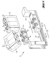
- Fig. 3 shows a perspective view of a part of an analyzer according to the invention which includes a rack of the type described above with reference to Figures 1 and 2.
- the analyzer may comprise several electromechanical shaker devices 31 each of which is adapted for being connected to a removable part 21 of rack 11.
- shaker 31 Among the parts of shaker 31 represented in Fig. 3 are a carriage 34 and a disk 32 which carries an eccentric pin 36 and which is driven by a motor 33.
- motor 33 is a step motor.
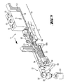
- Fig 4 shows a perspective view of shaker device 31.
- a carriage 34 which is part of shaker mechanism 31 is removably coupled to movable part 21 of rack 11.
- Carriage 34 is connected with a connection piece 38 by means of a joint 40.
- Connection piece 38 is rotatably connected to a cylindrical joint combined with a revolute joint 37 which is in turn connected with eccentric pin 36.
- the lower part of carriage 34 includes a slide bearing 53 which allows carriage 34 to slide back and forth along the length axis 39 of a guiding shaft 64 and also to oscillate back and forth around axis 39.
- Guiding shaft 64 has a fixed position and is parallel to the X-axis. Guiding shaft 64 is supported by support elements 69 and 69a respectively.
- Fig. 4 also shows a support plate 68 for the frame 12 of rack 11.
- the eccentricity e is the distance that separates the axis of rotation 29 of motor 33 and the length axis of pin 36 from each other.
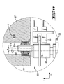
- Fig. 5 shows a partial cross-sectional view of means for removably coupling movable part 21 of rack 11 with a carriage 34 of a shaker device 31 by means of a leaf spring 35.
- leaf spring 35 As shown by Figures 5 and 6, one end of leaf spring 35 is mechanically connected with movable part 21.
- Fig. 5 shows a rack 11 in a position at which movable part 21 is not engaged with carriage 34 by means of a leaf spring 35.
- a casing 16 containing liquid containers 15 which do not have to be agitated is mounted on section 13 of rack 11.
- movable part 21 is loosely connected with frame 12. This loose connection may be achieved by means of pins 41, 42, 43 which cooperate with corresponding openings 51, 52 of removable part 21 shown in Fig. 2. Pins 41, 42, 43 are inserted in suitable openings of frame 12.
- Fig. 6 shows a partial cross-sectional view of a movable part 21 of rack 11 coupled with carriage 34 of shaker device 31 by means of leaf spring 35.
- the mechanical components of shaker device 31 may be made of any suitable material, such us, for example, aluminum or of steel.
- Fig. 7 shows curves representing the variation with time of the components of motion of carriage 34 in three orthogonal directions X, Y, Z and of an angular component ⁇ corresponding to the oscillation of carriage 34 around axis 39.
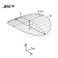
- Fig. 8 shows a three-dimensional path M of motion of a point of casing 16 when it is moved by shaker device 31 shown by Fig. 4.
- An encoder 28 (shown in Fig. 9) is connected with motor 33 and is arranged in the housing of motor 33.
- the angular position of motor 33 is controlled by means of encoder 28 which for this purpose receives signals from an electro-optical position detector 66 described hereinafter with reference to Figures 9 and 10.
- Control of the angular position of motor 33 by means of encoder 28 and detector 66 makes it possible to position liquid container carrier 16 and thereby liquid container 16 in a reproducible way, at a predetermined position, e.g. at the end of a shaking operation of shaker device 31.
- this second analyzer embodiment is similar to the structure of the first embodiment described above with reference to Figures 1-8, but this second analyzer embodiment comprises a second embodiment of a shaker device which is described hereinafter with reference to Figures 9 and 10.
- Fig. 9 shows a perspective view of a shaker device 67 which is part of an analyzer according to the invention and which serves for moving the movable part 21 of rack 11 and thereby casing 16 in the same way as achieved with shaker 31 and thereby effect the motions represented in Figures 7 and 8.
- Shaker device has a carriage 63 which has the same or similar structure and function as carriage 34 described above with reference to Figures 4-6.
- the lower part of carriage 63 includes a slide bearing 62 which allows carriage 34 to slide back and forth along the length axis 39 of a guiding shaft 64 and also to oscillate back and forth around axis 39.
- Guiding shaft 64 has a fixed position and is parallel to the X-axis. Guiding shaft 64 is supported by support elements 69 and 69a respectively.
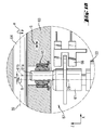
- Shaker device 67 is shown in detail in Fig. 10. Shaker device 67 differs from shaker device 31 represented in Fig. 4 in that it comprises a pin 61a inserted in a ball and socket joint 65 which as shown in Fig. 9 is directly connected to carriage 63 of shaker device 67 and not by means of a joint 37 and a connection piece 38 as is the case when shaker device 31 shown in Fig. 4 is used.
- Fig. 9 also shows support plate 68 for the frame 12 of rack 11. Pin 61a is driven by a shaft 61 of a step motor 33.
- Fig. 10 also shows the eccentricity e of pin 61a, i.e. the distance e between the length symmetry axis 61 b of pin 61a and the rotation axis 29 of shaft 61 of motor 33.
- the lower part of carriage 63 includes a slide bearing 62 which allows carriage 63 to slide back and forth along the length axis 39 of a guiding shaft 64 and also to oscillate back and forth around axis 39.
- Guiding shaft 64 has a fixed position and is parallel to the X-axis. Guiding shaft 64 is supported by support elements 69 and 69a respectively.
- Figures 9 and 10 also show an electro-optical position detector 66 which accurately detects the angular position of motor shaft 61.
- Detector 66 provides signals to an encoder 28 (shown in Fig. 9) which serves for accurately positioning motor shaft 61.
- Control of the angular position of motor shaft 61 by means of encoder 28 and detector 66 makes it possible to position liquid container carrier 16 and thereby liquid container 16 in a reproducible way, at a predetermined position, e.g. at the end of a shaking operation of shaker device 67.
- Fig. 11 shows a part of a third embodiment of an analyzer according to the invention. This embodiment differs from the above described first and second embodiments in that it does not use the type of rack described above with reference to Figures 1 and 2, but a rack 11a built as a single piece frame 12 having a shape adapted for receiving liquid containers 16.
- the third embodiment of the analyzer also comprises a shaker device 70 which has a similar structure as shaker device 67 in Fig. 9.
- Shaker device 70 comprises a movable support plate 79 adapted for receiving rack 11a.
- Rack 11a and movable plate 79 are adapted for being removably connectable with each other.
- the lower part of movable plate 79 is formed as a guiding support member 77.
- shaker device 70 further comprises an eccentric pin 71a driven by a shaft 71 of a step motor 33.
- Pin 71a is inserted in a ball and socket joint 78 which, as shown in Fig. 12, is directly connected to support member 77 of movable plate 79.
- Fig. 12 also shows the eccentricity e of pin 71a, i.e. the distance e between the length symmetry axis 71b of pin 71a and the rotation axis 29 of shaft 71 of motor 33.
- the lower part of guiding support member 77 includes a slide bearing 72 which allows support member 77 and thereby movable plate 79 to slide back and forth along the length axis 39 of a guiding shaft 75 and also to oscillate back and forth around axis 39.
- Guiding shaft 75 has a fixed position and is parallel to the X-axis.
- Shaker device 70 moves rack 11a and thereby casing 16 in the same way as achieved with shaker 31 in the embodiment described with reference to Figures 1-8. Casing 16 in Fig. 11 is thus moved by shaker device 70 as represented in Figures 7 and 8.
- Figures 11 and 12 also show an electro-optical position detector 66 which accurately detects the angular position of motor shaft 71.
- Detector 66 provides signals to an encoder 28 (shown in Fig. 9) which serves for accurately positioning motor shaft 71.
- Control of the angular position of motor shaft 71 by means of encoder 28 and detector 66 makes it possible to position liquid container carrier 16 and thereby liquid container 16 in a reproducible way, at a predetermined position, e.g. at the end of a shaking operation of shaker device 70.
- Fig. 13 shows a part of a fourth embodiment of an analyzer according to the invention.
- This fourth embodiment also uses a rack 11a of the type shown in Fig. 11 and comprises a movable support plate 89 similar to movable plate 79 of the third embodiment.
- This fourth embodiment of an analyzer according to the invention differs from the above described third analyzer embodiment in that it comprises a shaker device 80 which is not connected to the lower and central part of the movable plate, but to one end thereof formed as a bar 87.
- shaker device 80 has a similar structure as shaker device 70 in Fig. 11.
- Shaker device 80 comprises a movable support plate 89 adapted for receiving rack 11a.
- Rack 11a and movable plate 89 are adapted for being removably connectable with each other.
- shaker device 80 further comprises an eccentric pin 81a driven by a shaft 81 of a step motor 33.
- Pin 81a is inserted in a ball and socket joint 88 which as shown in Fig. 14 is directly connected to bar 87 at one end of movable plate 89.
- Fig. 14 also shows the eccentricity e of pin 81a, i.e. the distance e between the length symmetry axis 81b of pin 81a and the rotation axis 29 of shaft 81 of motor 33.
- the lower part of movable plate 89 is formed as a guiding support member which includes slide bearings 82 which allow movable plate 89 to slide back and forth along the length axis 39 of guiding shafts 84 and 85 and also to oscillate back and forth around axis 39.
- Guiding shafts 84 and 85 have a fixed position and are parallel to the X-axis.
- Shaker device 80 also moves rack 11a and thereby casing 16 in the same way as achieved with shaker 31 in the embodiment described with reference to Figures 1-8. Casing 16 in Fig. 11 is thus moved by shaker device 80 as represented in Figures 7 and 8.
- Figures 13 and 14 also show an electro-optical position detector 66 which accurately detects the angular position of motor shaft 81.
- Detector 66 provides signals to an encoder 28 (shown in Fig. 9) which serves for accurately positioning motor shaft 81.
- Control of the angular position of motor shaft 81 by means of encoder 28 and detector 66 makes it possible to position liquid container carrier 16 and thereby liquid container 16 in a reproducible way, at a predetermined position, e.g. at the end of a shaking operation of shaker device 80.
- this fifth analyzer embodiment is similar to the structure of the first embodiment described above with reference to Figures 1-8, but this second analyzer embodiment comprises a second embodiment of a shaker device which is described hereinafter with reference to Figures 15 to 17.
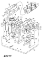
- Fig. 15 shows a perspective view of two separate shaker devices side by side.
- Each shaker device is mounted on a basis plate 96 of the analyzer and comprises a movable carriage 34 adapted for being removably connected to the movable part 21 of a rack 11 as described above with reference to Figures 1-6, rigid support plates 92 and 93 fixedly mounted on basis plate 96, and a cross-shaped support plate 91, on which is mounted the motor 33 of the shaker device.
- Support plates 92 and 93 are arranged on opposite sides of movable carriage 34.
- movable carriage 34 is connected to support plates 92, 93 by means of a flexible element 101.
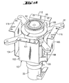
- flexible element 101 is a single-piece element which, as shown by Figures 16 and 17, comprises a flat central part 106 which lies in a plane, a first pair of rectangular flaps 102, 103 parallel to each other, and a second pair of rectangular flaps 104, 105 parallel to each other. Flaps 104 and 105 extend along planes which are normal to flaps 102, 103.
- the shaft of motor 33 passes through an opening 108 of flexible element 101 and drives an eccentric ball 94 which cooperates with a roller bearing 95 and moves carriage 34.
- Each of flaps 102, 103 extends from central part 106 along a plane normal to the plane defined by the surface of central part 106. Flaps 102 and 103 have end parts 111 and 112 respectively. End parts 111, 112 are connected to end parts 113 respectively 114 of said movable carriage 34. End parts 113 and 114 lie on opposite sides of movable carriage 34.
- Each of flaps 104, 105 extend from central part 106 along a plane normal to the plane defined by the surface of central part 106. Flaps 104, 105 have end parts 115 and 116 respectively. End part 115 is connected to stationary support plate 93. End part 116 is connected to stationary support plate 92.
- the embodiment just described offers the advantage of having less number of parts than the other shaker embodiments described above, and this reduces the manufacturing costs and makes the operation more reliable and less prone to failure due to mechanical problems.
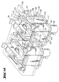
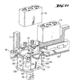
- the shaker device is mounted on an intermediate support plate 125 of the analyzer instead of support plates 92 and 93, and flexible element 101 is not a single-piece element, but is a structure which comprises a central plate 107 lying in a plane, a first pair of individual rectangular flaps 102, 103 parallel to each other and a second pair of individual rectangular flaps 104, 105 parallel to each other. Flaps 104 and 105 extend along planes which are normal to flaps 102 and 103.
- Each of flaps 102, 103 has a first end part 109, 110 connected to central plate 107 by connecting pieces 126, 127 and a second end part 111 respectively 112 which are connected to end parts 113 and 114 of movable carriage 34 by means of connecting pieces 121 respectively 122. End parts 113 and 114 lie on opposite sides of movable carriage 34.
- the first end parts of flaps 102 and 103 may be connected to plate 107 by connecting pieces similar to connecting pieces 121, 122.
- Flap 104 has a first end part 117 connected by connecting piece 119 to central plate 107 and a second end part 115 opposite to the first end part and connected by a connecting piece 123 to intermediate support plate 125 of the analyzer at a place located on one side of said movable carriage 34, whereas flap 105 has a first end part 118 connected by a connecting piece 120 to central plate 107 and a second end part 116 opposite to the first end part and connected by connecting piece 124 to intermediate support plate 125 of the analyzer at a place located on the opposite side of movable carriage 34.
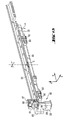
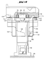
- Fig. 20 illustrates the use of a shaker device of the type described above with reference to Figures 15-17 in an analyzer in which a casing 16 containing one or more reagent containers is positioned on the movable part 21 of a rack and this movable part is removably connected to the movable carriage 34 of the shaker device.
- Fig. 20 includes a partial view of a rack 11 of the type shown in Figures 1-6, a part of a support plate 68 and a part of support elements 131 and 132 which support plate 68. Support elements 131 and 132 are rigidly connected with basis plate 96.
- Figure 21 shows a partial perspective view of a variant of the embodiment shown by Fig. 20, wherein instead of a single-piece flexible element 101 a flexible structure of the type described above with reference to Fig. 18 is used.
- Fig. 22 illustrates the use of a shaker device of the type described above with reference to Figures 15-17 in an analyzer in which a tray 133 is used as carrier of liquid containers that have to be agitated during some time intervals.
- Figure 23 shows a variant of the embodiment shown by Fig. 22, wherein instead of a single-piece flexible element 101 a flexible structure of the type described above with reference to Fig. 18 is used.
Landscapes
- Chemical & Material Sciences (AREA)
- Chemical Kinetics & Catalysis (AREA)
- Health & Medical Sciences (AREA)
- Biochemistry (AREA)
- Life Sciences & Earth Sciences (AREA)
- Analytical Chemistry (AREA)
- Physics & Mathematics (AREA)
- General Health & Medical Sciences (AREA)
- General Physics & Mathematics (AREA)
- Immunology (AREA)
- Pathology (AREA)
- Clinical Laboratory Science (AREA)
- Automatic Analysis And Handling Materials Therefor (AREA)
- Mixers With Rotating Receptacles And Mixers With Vibration Mechanisms (AREA)
Priority Applications (1)
| Application Number | Priority Date | Filing Date | Title |
|---|---|---|---|
| EP05077316.7A EP1655609B1 (fr) | 2004-11-04 | 2005-10-11 | Ensemble support d'eprouvettes comprenant une partie mouvant pour agiter d'échantillon |
Applications Claiming Priority (2)
| Application Number | Priority Date | Filing Date | Title |
|---|---|---|---|
| EP20040078041 EP1655071A1 (fr) | 2004-11-04 | 2004-11-04 | Ensemble support d'eprouvettes comprenant une partie mouvant pour agiter d'échantillon |
| EP05077316.7A EP1655609B1 (fr) | 2004-11-04 | 2005-10-11 | Ensemble support d'eprouvettes comprenant une partie mouvant pour agiter d'échantillon |
Publications (2)
| Publication Number | Publication Date |
|---|---|
| EP1655609A1 true EP1655609A1 (fr) | 2006-05-10 |
| EP1655609B1 EP1655609B1 (fr) | 2013-09-18 |
Family
ID=36168827
Family Applications (1)
| Application Number | Title | Priority Date | Filing Date |
|---|---|---|---|
| EP05077316.7A Expired - Lifetime EP1655609B1 (fr) | 2004-11-04 | 2005-10-11 | Ensemble support d'eprouvettes comprenant une partie mouvant pour agiter d'échantillon |
Country Status (1)
| Country | Link |
|---|---|
| EP (1) | EP1655609B1 (fr) |
Cited By (7)
| Publication number | Priority date | Publication date | Assignee | Title |
|---|---|---|---|---|
| EP1536880A4 (fr) * | 2002-08-27 | 2009-02-18 | Siemens Healthcare Diagnostics | Procede et appareil permettant de melanger des echantillons liquides au moyen d'une action de melange sinusoidale |
| EP2148206A1 (fr) * | 2008-07-25 | 2010-01-27 | F.Hoffmann-La Roche Ag | Système de laboratoire pour la manipulation de portoir de tubes d'échantillons, et élément d'alignement pour portoirs de tubes d'échantillons et ensemble recevant le plateau de portoirs |
| WO2010054799A1 (fr) * | 2008-11-14 | 2010-05-20 | Pvt Probenverteiltechnik Gmbh | Dispositif de rack pour un système de distribution d'échantillons |
| EP3222990A1 (fr) * | 2016-03-23 | 2017-09-27 | Siemens Healthcare Diagnostics Products GmbH | Procede de melange de liquides reactifs dans un appareil d'analyse automatique |
| CN109985686A (zh) * | 2019-04-29 | 2019-07-09 | 迈克医疗电子有限公司 | 样本架和样本分析仪 |
| EP3575800A1 (fr) * | 2018-06-01 | 2019-12-04 | The Charles Stark Draper Laboratory, Inc. | Identification automatisée de bactéries et dispositif de profilage de la sensibilité aux antibiotiques |
| CN114544899B (zh) * | 2022-03-05 | 2024-01-26 | 安徽省国众检测科技有限公司 | 一种水源污染检测操作装置 |
Citations (4)
| Publication number | Priority date | Publication date | Assignee | Title |
|---|---|---|---|---|
| US5632388A (en) * | 1995-01-30 | 1997-05-27 | Forma Scientific, Inc. | Test tube rack assembly |
| US5665309A (en) * | 1995-02-07 | 1997-09-09 | Abx | Device for agitating and for taking samples of blood products from tubes which are grouped together in racks |
| WO1998057739A1 (fr) * | 1997-06-16 | 1998-12-23 | Chemspeed Ltd. | Dispositif de retenue d'eprouvettes |
| WO2001028680A2 (fr) * | 1999-10-20 | 2001-04-26 | Gentra Systems, Inc. | Appareil a melanger et a verser et recipient correspondant |
-
2005
- 2005-10-11 EP EP05077316.7A patent/EP1655609B1/fr not_active Expired - Lifetime
Patent Citations (4)
| Publication number | Priority date | Publication date | Assignee | Title |
|---|---|---|---|---|
| US5632388A (en) * | 1995-01-30 | 1997-05-27 | Forma Scientific, Inc. | Test tube rack assembly |
| US5665309A (en) * | 1995-02-07 | 1997-09-09 | Abx | Device for agitating and for taking samples of blood products from tubes which are grouped together in racks |
| WO1998057739A1 (fr) * | 1997-06-16 | 1998-12-23 | Chemspeed Ltd. | Dispositif de retenue d'eprouvettes |
| WO2001028680A2 (fr) * | 1999-10-20 | 2001-04-26 | Gentra Systems, Inc. | Appareil a melanger et a verser et recipient correspondant |
Cited By (12)
| Publication number | Priority date | Publication date | Assignee | Title |
|---|---|---|---|---|
| EP1536880A4 (fr) * | 2002-08-27 | 2009-02-18 | Siemens Healthcare Diagnostics | Procede et appareil permettant de melanger des echantillons liquides au moyen d'une action de melange sinusoidale |
| EP2148206A1 (fr) * | 2008-07-25 | 2010-01-27 | F.Hoffmann-La Roche Ag | Système de laboratoire pour la manipulation de portoir de tubes d'échantillons, et élément d'alignement pour portoirs de tubes d'échantillons et ensemble recevant le plateau de portoirs |
| EP2530025A1 (fr) * | 2008-07-25 | 2012-12-05 | F. Hoffmann-La Roche AG | élément d' alignement pour portoirs de tubes d' échantillons |
| US8580195B2 (en) | 2008-07-25 | 2013-11-12 | Roche Diagnostics Operations, Inc. | Laboratory system for handling sample tube racks, an alignment element for sample tube racks and a rack tray receiver assembly |
| US9297822B2 (en) | 2008-07-25 | 2016-03-29 | Roche Diagnostics Operations, Inc. | Laboratory system for handling sample tube racks, an alignment element for sample tube racks and a rack tray receiver assembly |
| WO2010054799A1 (fr) * | 2008-11-14 | 2010-05-20 | Pvt Probenverteiltechnik Gmbh | Dispositif de rack pour un système de distribution d'échantillons |
| US8940252B2 (en) | 2008-11-14 | 2015-01-27 | Roche Diagnostics Operations, Inc. | Rack apparatus for a sample distribution system |
| EP3222990A1 (fr) * | 2016-03-23 | 2017-09-27 | Siemens Healthcare Diagnostics Products GmbH | Procede de melange de liquides reactifs dans un appareil d'analyse automatique |
| EP3575800A1 (fr) * | 2018-06-01 | 2019-12-04 | The Charles Stark Draper Laboratory, Inc. | Identification automatisée de bactéries et dispositif de profilage de la sensibilité aux antibiotiques |
| CN109985686A (zh) * | 2019-04-29 | 2019-07-09 | 迈克医疗电子有限公司 | 样本架和样本分析仪 |
| CN109985686B (zh) * | 2019-04-29 | 2024-05-14 | 迈克医疗电子有限公司 | 样本架和样本分析仪 |
| CN114544899B (zh) * | 2022-03-05 | 2024-01-26 | 安徽省国众检测科技有限公司 | 一种水源污染检测操作装置 |
Also Published As
| Publication number | Publication date |
|---|---|
| EP1655609B1 (fr) | 2013-09-18 |
Similar Documents
| Publication | Publication Date | Title |
|---|---|---|
| CA2525359C (fr) | Ratelier pour appareils d'analyse et appareil d'analyse comportant un tel ratelier | |
| JP6014424B2 (ja) | 撹拌装置及び検体分析装置 | |
| EP0435481B1 (fr) | Dispositif pour agiter sélectivement des composants réactifs | |
| US9604185B2 (en) | Apparatus for indexing and agitating fluid containers | |
| US8747747B2 (en) | Reader devices for manipulating multi-fluidic cartridges for sample analysis | |
| US8826752B2 (en) | Multi-fluidic cartridges for sample analysis and methods for using same | |
| EP1655609B1 (fr) | Ensemble support d'eprouvettes comprenant une partie mouvant pour agiter d'échantillon | |
| EP0525577B1 (fr) | Dispositif pour support de test | |
| WO2007124817A1 (fr) | Dispositif agitateur-secoueur pour appareil a analyseur et analyseur incorporant ce dispositif | |
| EP1647826A1 (fr) | Analyseur, couvercle et dispositif de stockage de réactif | |
| US20150168435A1 (en) | Automated Analyzer | |
| JP2005537127A (ja) | 正弦波混合作用を使用して液体サンプルを混合する方法および装置 | |
| JP2004301843A (ja) | 固定多機能プローブを有する分析装置 | |
| JP4819324B2 (ja) | 同心のロータを備えたアナライザ | |
| CN113909084A (zh) | 一种回旋振荡机构 | |
| EP2023148A1 (fr) | Instrument d'analyse | |
| EP0596987A1 (fr) | Entrainement de melangeur a tourbillon. | |
| JPWO2020075806A1 (ja) | 係止構造 | |
| EP3226000B1 (fr) | Dispositif de rotation | |
| WO2012105252A1 (fr) | Dispositif et procédé d'agitation | |
| CN113624961A (zh) | 侧向流动诊断测试装置 | |
| CN213456809U (zh) | 一种食品药品检验用分析滴定装置 | |
| EP4678355A1 (fr) | Dispositif de préhension, dispositif d'analyse automatique et procédé de préhension | |
| JP6937222B2 (ja) | 自動分析装置及び磁気攪拌装置 | |
| WO2026048227A1 (fr) | Analyseur automatique et stockage de récipients |
Legal Events
| Date | Code | Title | Description |
|---|---|---|---|
| PUAI | Public reference made under article 153(3) epc to a published international application that has entered the european phase |
Free format text: ORIGINAL CODE: 0009012 |
|
| AK | Designated contracting states |
Kind code of ref document: A1 Designated state(s): AT BE BG CH CY CZ DE DK EE ES FI FR GB GR HU IE IS IT LI LT LU LV MC NL PL PT RO SE SI SK TR |
|
| AX | Request for extension of the european patent |
Extension state: AL BA HR MK YU |
|
| RIN1 | Information on inventor provided before grant (corrected) |
Inventor name: MEYER, THOMAS Inventor name: SCHORNO, RETO Inventor name: MUELLER, SIEGFRIED Inventor name: SCHLAUBITZ, THOMAS |
|
| RAP1 | Party data changed (applicant data changed or rights of an application transferred) |
Owner name: ROCHE DIAGNOSTICS GMBH Owner name: F.HOFFMANN-LA ROCHE AG |
|
| 17P | Request for examination filed |
Effective date: 20060828 |
|
| 17Q | First examination report despatched |
Effective date: 20060928 |
|
| AKX | Designation fees paid |
Designated state(s): AT BE BG CH CY CZ DE DK EE ES FI FR GB GR HU IE IS IT LI LT LU LV MC NL PL PT RO SE SI SK TR |
|
| GRAP | Despatch of communication of intention to grant a patent |
Free format text: ORIGINAL CODE: EPIDOSNIGR1 |
|
| INTG | Intention to grant announced |
Effective date: 20130423 |
|
| GRAS | Grant fee paid |
Free format text: ORIGINAL CODE: EPIDOSNIGR3 |
|
| GRAA | (expected) grant |
Free format text: ORIGINAL CODE: 0009210 |
|
| AK | Designated contracting states |
Kind code of ref document: B1 Designated state(s): AT BE BG CH CY CZ DE DK EE ES FI FR GB GR HU IE IS IT LI LT LU LV MC NL PL PT RO SE SI SK TR |
|
| REG | Reference to a national code |
Ref country code: GB Ref legal event code: FG4D |
|
| REG | Reference to a national code |
Ref country code: CH Ref legal event code: EP |
|
| REG | Reference to a national code |
Ref country code: IE Ref legal event code: FG4D |
|
| REG | Reference to a national code |
Ref country code: AT Ref legal event code: REF Ref document number: 633042 Country of ref document: AT Kind code of ref document: T Effective date: 20131015 |
|
| REG | Reference to a national code |
Ref country code: DE Ref legal event code: R096 Ref document number: 602005041246 Country of ref document: DE Effective date: 20131107 |
|
| PG25 | Lapsed in a contracting state [announced via postgrant information from national office to epo] |
Ref country code: CY Free format text: LAPSE BECAUSE OF FAILURE TO SUBMIT A TRANSLATION OF THE DESCRIPTION OR TO PAY THE FEE WITHIN THE PRESCRIBED TIME-LIMIT Effective date: 20130710 Ref country code: LT Free format text: LAPSE BECAUSE OF FAILURE TO SUBMIT A TRANSLATION OF THE DESCRIPTION OR TO PAY THE FEE WITHIN THE PRESCRIBED TIME-LIMIT Effective date: 20130918 Ref country code: SE Free format text: LAPSE BECAUSE OF FAILURE TO SUBMIT A TRANSLATION OF THE DESCRIPTION OR TO PAY THE FEE WITHIN THE PRESCRIBED TIME-LIMIT Effective date: 20130918 |
|
| REG | Reference to a national code |
Ref country code: NL Ref legal event code: VDEP Effective date: 20130918 |
|
| REG | Reference to a national code |
Ref country code: AT Ref legal event code: MK05 Ref document number: 633042 Country of ref document: AT Kind code of ref document: T Effective date: 20130918 |
|
| REG | Reference to a national code |
Ref country code: LT Ref legal event code: MG4D |
|
| PG25 | Lapsed in a contracting state [announced via postgrant information from national office to epo] |
Ref country code: GR Free format text: LAPSE BECAUSE OF FAILURE TO SUBMIT A TRANSLATION OF THE DESCRIPTION OR TO PAY THE FEE WITHIN THE PRESCRIBED TIME-LIMIT Effective date: 20131219 Ref country code: LV Free format text: LAPSE BECAUSE OF FAILURE TO SUBMIT A TRANSLATION OF THE DESCRIPTION OR TO PAY THE FEE WITHIN THE PRESCRIBED TIME-LIMIT Effective date: 20130918 Ref country code: SI Free format text: LAPSE BECAUSE OF FAILURE TO SUBMIT A TRANSLATION OF THE DESCRIPTION OR TO PAY THE FEE WITHIN THE PRESCRIBED TIME-LIMIT Effective date: 20130918 Ref country code: FI Free format text: LAPSE BECAUSE OF FAILURE TO SUBMIT A TRANSLATION OF THE DESCRIPTION OR TO PAY THE FEE WITHIN THE PRESCRIBED TIME-LIMIT Effective date: 20130918 |
|
| PG25 | Lapsed in a contracting state [announced via postgrant information from national office to epo] |
Ref country code: CY Free format text: LAPSE BECAUSE OF FAILURE TO SUBMIT A TRANSLATION OF THE DESCRIPTION OR TO PAY THE FEE WITHIN THE PRESCRIBED TIME-LIMIT Effective date: 20130918 Ref country code: BE Free format text: LAPSE BECAUSE OF FAILURE TO SUBMIT A TRANSLATION OF THE DESCRIPTION OR TO PAY THE FEE WITHIN THE PRESCRIBED TIME-LIMIT Effective date: 20130918 |
|
| PG25 | Lapsed in a contracting state [announced via postgrant information from national office to epo] |
Ref country code: EE Free format text: LAPSE BECAUSE OF FAILURE TO SUBMIT A TRANSLATION OF THE DESCRIPTION OR TO PAY THE FEE WITHIN THE PRESCRIBED TIME-LIMIT Effective date: 20130918 Ref country code: CZ Free format text: LAPSE BECAUSE OF FAILURE TO SUBMIT A TRANSLATION OF THE DESCRIPTION OR TO PAY THE FEE WITHIN THE PRESCRIBED TIME-LIMIT Effective date: 20130918 Ref country code: NL Free format text: LAPSE BECAUSE OF FAILURE TO SUBMIT A TRANSLATION OF THE DESCRIPTION OR TO PAY THE FEE WITHIN THE PRESCRIBED TIME-LIMIT Effective date: 20130918 Ref country code: SK Free format text: LAPSE BECAUSE OF FAILURE TO SUBMIT A TRANSLATION OF THE DESCRIPTION OR TO PAY THE FEE WITHIN THE PRESCRIBED TIME-LIMIT Effective date: 20130918 Ref country code: RO Free format text: LAPSE BECAUSE OF FAILURE TO SUBMIT A TRANSLATION OF THE DESCRIPTION OR TO PAY THE FEE WITHIN THE PRESCRIBED TIME-LIMIT Effective date: 20130918 Ref country code: IS Free format text: LAPSE BECAUSE OF FAILURE TO SUBMIT A TRANSLATION OF THE DESCRIPTION OR TO PAY THE FEE WITHIN THE PRESCRIBED TIME-LIMIT Effective date: 20140118 |
|
| PG25 | Lapsed in a contracting state [announced via postgrant information from national office to epo] |
Ref country code: AT Free format text: LAPSE BECAUSE OF FAILURE TO SUBMIT A TRANSLATION OF THE DESCRIPTION OR TO PAY THE FEE WITHIN THE PRESCRIBED TIME-LIMIT Effective date: 20130918 Ref country code: PL Free format text: LAPSE BECAUSE OF FAILURE TO SUBMIT A TRANSLATION OF THE DESCRIPTION OR TO PAY THE FEE WITHIN THE PRESCRIBED TIME-LIMIT Effective date: 20130918 Ref country code: ES Free format text: LAPSE BECAUSE OF FAILURE TO SUBMIT A TRANSLATION OF THE DESCRIPTION OR TO PAY THE FEE WITHIN THE PRESCRIBED TIME-LIMIT Effective date: 20130918 |
|
| REG | Reference to a national code |
Ref country code: CH Ref legal event code: PL |
|
| REG | Reference to a national code |
Ref country code: DE Ref legal event code: R097 Ref document number: 602005041246 Country of ref document: DE |
|
| PG25 | Lapsed in a contracting state [announced via postgrant information from national office to epo] |
Ref country code: MC Free format text: LAPSE BECAUSE OF FAILURE TO SUBMIT A TRANSLATION OF THE DESCRIPTION OR TO PAY THE FEE WITHIN THE PRESCRIBED TIME-LIMIT Effective date: 20130918 Ref country code: PT Free format text: LAPSE BECAUSE OF FAILURE TO SUBMIT A TRANSLATION OF THE DESCRIPTION OR TO PAY THE FEE WITHIN THE PRESCRIBED TIME-LIMIT Effective date: 20140120 |
|
| PLBE | No opposition filed within time limit |
Free format text: ORIGINAL CODE: 0009261 |
|
| STAA | Information on the status of an ep patent application or granted ep patent |
Free format text: STATUS: NO OPPOSITION FILED WITHIN TIME LIMIT |
|
| REG | Reference to a national code |
Ref country code: IE Ref legal event code: MM4A |
|
| PG25 | Lapsed in a contracting state [announced via postgrant information from national office to epo] |
Ref country code: LI Free format text: LAPSE BECAUSE OF NON-PAYMENT OF DUE FEES Effective date: 20131031 Ref country code: CH Free format text: LAPSE BECAUSE OF NON-PAYMENT OF DUE FEES Effective date: 20131031 |
|
| 26N | No opposition filed |
Effective date: 20140619 |
|
| PG25 | Lapsed in a contracting state [announced via postgrant information from national office to epo] |
Ref country code: IT Free format text: LAPSE BECAUSE OF FAILURE TO SUBMIT A TRANSLATION OF THE DESCRIPTION OR TO PAY THE FEE WITHIN THE PRESCRIBED TIME-LIMIT Effective date: 20130918 |
|
| REG | Reference to a national code |
Ref country code: DE Ref legal event code: R097 Ref document number: 602005041246 Country of ref document: DE Effective date: 20140619 |
|
| PG25 | Lapsed in a contracting state [announced via postgrant information from national office to epo] |
Ref country code: DK Free format text: LAPSE BECAUSE OF FAILURE TO SUBMIT A TRANSLATION OF THE DESCRIPTION OR TO PAY THE FEE WITHIN THE PRESCRIBED TIME-LIMIT Effective date: 20130918 |
|
| PG25 | Lapsed in a contracting state [announced via postgrant information from national office to epo] |
Ref country code: IE Free format text: LAPSE BECAUSE OF NON-PAYMENT OF DUE FEES Effective date: 20131011 |
|
| PG25 | Lapsed in a contracting state [announced via postgrant information from national office to epo] |
Ref country code: TR Free format text: LAPSE BECAUSE OF FAILURE TO SUBMIT A TRANSLATION OF THE DESCRIPTION OR TO PAY THE FEE WITHIN THE PRESCRIBED TIME-LIMIT Effective date: 20130918 |
|
| PG25 | Lapsed in a contracting state [announced via postgrant information from national office to epo] |
Ref country code: BG Free format text: LAPSE BECAUSE OF FAILURE TO SUBMIT A TRANSLATION OF THE DESCRIPTION OR TO PAY THE FEE WITHIN THE PRESCRIBED TIME-LIMIT Effective date: 20130918 Ref country code: HU Free format text: LAPSE BECAUSE OF FAILURE TO SUBMIT A TRANSLATION OF THE DESCRIPTION OR TO PAY THE FEE WITHIN THE PRESCRIBED TIME-LIMIT; INVALID AB INITIO Effective date: 20051011 Ref country code: LU Free format text: LAPSE BECAUSE OF NON-PAYMENT OF DUE FEES Effective date: 20131011 |
|
| REG | Reference to a national code |
Ref country code: FR Ref legal event code: PLFP Year of fee payment: 12 |
|
| REG | Reference to a national code |
Ref country code: FR Ref legal event code: PLFP Year of fee payment: 13 |
|
| REG | Reference to a national code |
Ref country code: FR Ref legal event code: PLFP Year of fee payment: 14 |
|
| PGFP | Annual fee paid to national office [announced via postgrant information from national office to epo] |
Ref country code: GB Payment date: 20240919 Year of fee payment: 20 |
|
| PGFP | Annual fee paid to national office [announced via postgrant information from national office to epo] |
Ref country code: FR Payment date: 20240919 Year of fee payment: 20 |
|
| PGFP | Annual fee paid to national office [announced via postgrant information from national office to epo] |
Ref country code: DE Payment date: 20240919 Year of fee payment: 20 |
|
| REG | Reference to a national code |
Ref country code: DE Ref legal event code: R071 Ref document number: 602005041246 Country of ref document: DE |
|
| REG | Reference to a national code |
Ref country code: GB Ref legal event code: PE20 Expiry date: 20251010 |