EP1655801A1 - Symmetrische Dipolantenne - Google Patents
Symmetrische Dipolantenne Download PDFInfo
- Publication number
- EP1655801A1 EP1655801A1 EP04256929A EP04256929A EP1655801A1 EP 1655801 A1 EP1655801 A1 EP 1655801A1 EP 04256929 A EP04256929 A EP 04256929A EP 04256929 A EP04256929 A EP 04256929A EP 1655801 A1 EP1655801 A1 EP 1655801A1
- Authority
- EP
- European Patent Office
- Prior art keywords
- coaxial cable
- dipole
- stubs
- dipole antenna
- conductor
- Prior art date
- Legal status (The legal status is an assumption and is not a legal conclusion. Google has not performed a legal analysis and makes no representation as to the accuracy of the status listed.)
- Granted
Links
- 239000004020 conductor Substances 0.000 claims abstract description 118
- 230000008878 coupling Effects 0.000 claims abstract description 23
- 238000010168 coupling process Methods 0.000 claims abstract description 23
- 238000005859 coupling reaction Methods 0.000 claims abstract description 23
- 239000007769 metal material Substances 0.000 claims description 3
- 238000010586 diagram Methods 0.000 description 11
- 238000012986 modification Methods 0.000 description 3
- 230000004048 modification Effects 0.000 description 3
- 230000009466 transformation Effects 0.000 description 3
- 238000005259 measurement Methods 0.000 description 2
- 230000005855 radiation Effects 0.000 description 1
Images


Classifications
-
- H—ELECTRICITY
- H01—ELECTRIC ELEMENTS
- H01P—WAVEGUIDES; RESONATORS, LINES, OR OTHER DEVICES OF THE WAVEGUIDE TYPE
- H01P5/00—Coupling devices of the waveguide type
- H01P5/08—Coupling devices of the waveguide type for linking dissimilar lines or devices
- H01P5/10—Coupling devices of the waveguide type for linking dissimilar lines or devices for coupling balanced lines or devices with unbalanced lines or devices
-
- H—ELECTRICITY
- H01—ELECTRIC ELEMENTS
- H01Q—ANTENNAS, i.e. RADIO AERIALS
- H01Q9/00—Electrically-short antennas having dimensions not more than twice the operating wavelength and consisting of conductive active radiating elements
- H01Q9/04—Resonant antennas
- H01Q9/16—Resonant antennas with feed intermediate between the extremities of the antenna, e.g. centre-fed dipole
- H01Q9/20—Two collinear substantially straight active elements; Substantially straight single active elements
Definitions
- the present invention relates a balanced dipole antenna, and more particularly, is directed to a symmetric balun used with a coaxial cable and dipole antenna.
- Fig. 1 shows dipole antenna 10 as having coaxial cable 5 having outer coaxial conductor 15 and inner coaxial conductor 16 used with a dipole antenna having dipole left blade 11 and dipole right blade 12.
- Coaxial outer conductor 15 is connected to dipole right blade 12.
- Coaxial inner conductor 16 is connected to dipole left blade 11 via wire 17.
- Coupled includes a radiative connection and a direct electrical connection.
- Common mode current flows on the outside of the coaxial line, reducing the efficiency of a pure dipole radiation pattern. Additionally, common mode current is caused by radiative coupling between the dipole antenna and an external coaxial cable. The majority of the distortion of the dipole antenna pattern is due to common mode current flow caused by the conducting imbalance of the structure, and a smaller amount of the distortion is due to radiative coupling.
- balun acts as a transformer, connecting a balanced two-conductor line to an unbalanced coaxial line.
- Fig. 2 shows dipole antenna 30 as having coaxial cable 5 connected to a dipole antenna using Roberts balun 40.
- the dipole antenna forms a balanced load (or source).
- Coaxial cable 5 connects to an unbalanced source (or load) and is connected to Roberts balun 40 at connection 41 which may be a threaded screw-type connection.
- Roberts balun 40 has a main coaxial segment having outer coaxial conductor 45 and inner coaxial conductor 46.
- Coaxial outer conductor 45 is connected to dipole right blade 32.
- Roberts balun 40 also has a short coaxial cable segment having outer conductor 35 and inner conductor 36.
- Roberts balun 40 is a quarter wavelength current choke.
- Coaxial outer conductor 35 is connected to dipole left blade 31.
- Coaxial inner conductors 35 and 45 are connected at their top ends via wire 37 and coupled to dipole left blade 31.
- Sliding bar 38 connects the bottom end of coaxial outer conductor 35 to coaxial outer conductor 45. Sliding bar 38 creates a short circuit, providing an infinite impedance across the terminals of dipole left arm 31 and dipole right arm 32.
- Fig. 3 shows dipole antenna 50 as having coaxial cable 5 coupled to a dipole antenna using IEEE-type balun 50, sometimes referred to as a Type III balun.
- the dipole antenna forms a balanced load (or source).
- Coaxial cable 5 connects to an unbalanced source (or load) and is connected to IEEE-type balun 50 at connection 51 which may be a threaded screw-type connection.
- IEEE-type balun 50 has a main coaxial segment having outer coaxial conductor 65 and inner coaxial conductor 66.
- Coaxial outer conductor 65 is electrically connected to dipole right blade 52.
- Coaxial inner conductor 66 is electrically connected to dipole left blade 51 via wire 57.
- IEEE-type balun 50 also has conductor 55 electrically connected to dipole left blade 51.
- IEEE-balun 50 is a quarter wavelength current choke.
- Conductor 55 is located generally parallel to the coaxial cable.
- Sliding bar 58 connects the bottom end of conductor 55 to coaxial outer conductor 65.
- Sliding bar 58 creates a short circuit, providing an infinite impedance across the terminals of dipole left arm 51 and dipole right arm 52.
- the quarter wavelength current choke in each of Figs. 2 and 3 serves to reduce common mode current.
- conventional baluns used with dipole antennas do not prevent radiative coupling between a coaxial cable and the dipole antenna and do not completely eliminate common mode current. Accordingly, there is room for an improved coupling between a coaxial cable and a dipole antenna.
- a balanced dipole antenna comprising a left dipole arm having a center end, a right dipole arm having a center end, a coaxial cable having an outer conductor and a single inner conductor and a top end electrically located between the center ends of the left and right dipole arms, a left stub coupling the left dipole arm and the coaxial cable, and a right stub coupling the right dipole arm and the coaxial cable.
- the structure of the balanced dipole antenna substantially eliminates radiative coupling between the coaxial cable and the left and right dipole arms, and substantially eliminates common mode current between the coaxial cable and the left and right dipole arms.
- the left and right stubs are formed of respective lengths of coaxial cable.
- one of the left and right stubs has an inner conductor that electrically connects to the inner conductor of the coaxial cable
- the other of the left and right stubs has an inner conductor that electrically connects to the outer conductor of the coaxial cable.
- the left and right stubs are formed of metallic material.
- the inner conductor of the coaxial cable is connected to one of the left and right dipole arms, and the outer conductor of the coaxial cable is connected to the other of the left and right dipole arms.
- a dipole antenna comprises a left dipole arm, a right dipole arm, a coaxial cable, and means for coupling the coaxial cable to the left and right dipole arms to substantially eliminate common mode current and radiative coupling between the coaxial cable and the left and right dipole arms.
- a symmetric balun comprising a left stub for coupling to a left arm of a dipole antenna, a right stub for coupling to a right arm of a dipole antenna, and a center branch for connecting to a coaxial cable, the center branch having an inner conductor and an outer conductor.
- Fig. 4 shows a prior art candelabra balun and transformer 70 fed by a special twin lead cable having outer conductor 85 and two inner conductors.
- the twin lead cable forms the center branch of a candelabra structure, which also has a left branch having left outer conductor 75 and a right branch having right outer conductor 95.
- a central segment having outer conductor 78 is located at the center of the candelabra structure next to the top of outer conductor 85.
- the bottom of outer conductor 78 is not electrically connected to sliding bar 78.
- Inner conductor 86 of the twin lead cable continues to the top of outer conductor 85.
- Inner conductor 76 of the twin lead cable feeds into the left branch of the candelabra structure.
- Conductor 79 has a U-shape and is located inside the left branch of the candelabra structure and inside the center branch of the candelabra structure.
- the right branch of the candelabra structure has inner conductor 96.
- the central segment of the candelabra structure has inner conductor 84.
- Wire 77 couples inner conductors 76 and 79 of the left branch of the candelabra structure to inner conductor 84 of the central segment of the candelabra structure.
- Wire 87 couples inner conductors 86 and 79 of the special twin lead cable forming the center branch of the candelabra structure to inner conductor 96 of the right branch of the candelabra structure.
- Candelabra balun and transformer 70 provides a transformation ratio of 4:1. Adding more branches, namely a total of three arms on each side of the center branch, provides a transformation ratio of 9:1. A total of arms on each side of the center branch, provides a transformation ratio of 16:1.
- a balanced dipole antenna has a coaxial cable connected between a load or source and the left and right dipole arms to substantially eliminate common mode current and radiative coupling between the coaxial cable and the left and right dipole arms.
- the connection between the source/load coaxial cable and the left and right dipole arms is a symmetric balun having a center branch that is an extension of the source/load coaxial cable, and left and right stubs.
- the outer conductors of the left and right stubs of the symmetric balun are respectively coupled to the left and right dipole arms, and one of the inner conductors of the left and right stubs is connected to the inner conductor of the center branch, while the other of the inner conductor of the left and right stubs is connected to the outer conductor of the center branch.
- the inner conductor of the center branch is electrically connected to one of the left and right dipole arms, while the outer conductor of the center branch is electrically connected to the other of the left and right dipole arms.
- a sliding bar at the base of the stubs electrically connects the outer conductors of the left and right stubs and the center branch.
- a dipole antenna using a first embodiment of a symmetric balun according to the present invention will now be discussed.
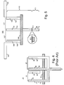
- Fig. 5 shows balanced dipole antenna 100 having coaxial cable 5 electrically connected to a dipole antenna using symmetric balun 110.
- Balanced dipole antenna 100 can be tuned for use over various frequencies, for instance over the 300 MHz - 1 GHz range.
- the dipole antenna forms a balanced load (or source).
- Left dipole arm 101 and right dipole arm 102 each have a length slightly less than ⁇ /4, where ⁇ is the free space wavelength of a center frequency of a bandwidth of signals being received or transmitted. Accordingly, the total length of balanced dipole antenna 100, including the width of symmetric balun 110, is about ⁇ /2.
- Left and right dipole arms 101, 102 are adjustable to the correct wavelength.
- Fig. 6 is a diagram showing a telescoping dipole blade.
- Coaxial cable 5 connects to an unbalanced source (or load) and is connected to symmetric balun 110 at connection 111 which may be a threaded screw-type connection, as shown in the circular inset of Fig. 5.
- Symmetric balun 110 has a left stub having outer coaxial conductor 105 and inner coaxial conductor 106, a center feeding branch that is a coaxial cable having outer coaxial conductor 115 and inner coaxial conductor 116, and a right stub having outer coaxial conductor 125 and inner coaxial conductor 126.
- Sliding bar 108 is located at the base of the left and right stubs and the center branch and electrically connects outer coaxial conductors 105, 115, 125, creating a short circuit, to provide an infinite impedance across the terminals of dipole left arm 101 and dipole right arm 102.
- Sliding bar 108 is adjusted so that the height of the stubs between dipole left and right arms 101, 102 and sliding bar 108 is about ⁇ /4.
- Fig. 7 is a diagram showing a sliding short circuit bar.
- Inner coaxial conductor 116 extends from the top of the center branch to the bottom of the center branch.
- Connection 111 is located at the bottom of the center branch and serves to electrically connect inner coaxial conductor 116 of the center branch to inner coaxial conductor 16 of coaxial cable 5, and to electrically connect outer coaxial conductor 115 of the center branch to outer coaxial conductor 15 of coaxial cable 5.
- Inner coaxial conductors 106, 126 extend from the top of the left and right stubs downwards to somewhat above the location of sliding bar 108.
- the height of inner coaxial conductors 106, 126 is about ⁇ g /4, where ⁇ g is the wavelength of a center frequency of a signal being received or transmitted inside the coaxial segments of the left and right branches.
- Wire 107 electrically connects inner coaxial conductor 106 of the left branch to inner coaxial conductor 116 of the center branch.
- Inner coaxial conductor 106 is electrically coupled to left dipole arm 101.
- Wire 117 electrically connects inner coaxial conductor 126 of the right branch to outer coaxial conductor 115 of the center branch.
- Inner coaxial conductor 126 is electrically coupled to right dipole arm 102.
- outer coaxial conductor 105 of the left stub is electrically connected to left dipole arm 101
- outer coaxial conductor 125 of the right stub is electrically connected to right dipole arm 102.
- Symmetric balun 110 comprises the left and right stubs and center branch and sliding bar 108. Symmetric balun 110 is a quarter wavelength current choke.
- a dipole antenna using a second embodiment of a symmetric balun according to the present invention will now be discussed.
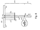
- Fig. 8 is a diagram showing coaxial cable 5 electrically connected to dipole antenna 200 using symmetric balun 210.
- Symmetric balun 210 is similar to symmetric balun 110, except that balun 210 uses metallic stubs on either side of its center coaxial branch, whereas balun 110 uses coaxial stubs on either side of its center coaxial branch.
- the dipole antenna forms a balanced load (or source).
- Left dipole arm 211 and right dipole arm 212 each have a length slightly less than ⁇ /4, where ⁇ is the free space wavelength of a center frequency of a bandwidth of signals being received or transmitted. Accordingly, the total length of balanced dipole antenna 200, including the width of symmetric balun 210, is about ⁇ /2.
- Left and right dipole arms 211, 212 are adjustable to the correct wavelength.
- Conductor 217 connects left dipole arm 211 to outside shield 215 of the center branch of symmetric balun 210.
- Conductor 218 connects right dipole arm 212 to feeding center conductor 216 of the center branch of symmetric balun 210.
- the center branch of symmetric balun 210 is electrically connected to coaxial cable 5 via connector 220, which may be a threaded screw-type connection.
- Center conductor 16 of coaxial cable 5 is in electrical contact with feeding center conductor 216 of the center branch.
- Outer shield 15 of coaxial cable 5 is electrically connected to outside shield 215 of the center branch.
- Left metallic stub 213 and right metallic stub 214 each have a length of ⁇ /4 and are respectively connected to left dipole arm 211 and right dipole arm 212.
- Sliding bar 219 is located at the base of the left and right stubs and the center branch and electrically connects conductors 213, 214, 215 creating a short circuit, to provide an infinite impedance across the terminals of dipole left arm 211 and dipole right arm 212.
- Sliding bar 219 is adjusted so that the height of the left and right stubs between dipole left and right arms 211, 212 and sliding bar 219 is about ⁇ /4.
- balanced dipole antenna 200 using symmetric balun 210 with adjustable telescoping arms 211, 212 was constructed. The length of the telescoping arms 211 and the position of shorting bar 219 were adjusted to minimize the common mode current of dipole antenna 200 at the operating frequency.
- Dipole antenna 200 and a commercially available dipole antenna with tunable frequency according to Fig. 2 were tested in an anechoic test chamber.
- a horizontal-vertical measurement antenna was at one end of the chamber, at the opposite end were a horizontal dipole antenna 200 and a vertical dipole antenna 200 arranged in a cross-fashion and mounted on a supporting mast.
- a horizontal commercially available dipole antenna according to Fig. 2 and a vertical commercially available dipole antenna according to Fig. 2 were arranged in cross-fashion and mounted on a supporting mast in the chamber.
- the test results are shown in Table 1.
- the vertical and horizontal numbers represent the path loss measured in dB.
- the difference numbers are simply the difference between vertical path loss and horizontal path loss.
Landscapes
- Variable-Direction Aerials And Aerial Arrays (AREA)
- Details Of Aerials (AREA)
- Support Of Aerials (AREA)
Priority Applications (8)
| Application Number | Priority Date | Filing Date | Title |
|---|---|---|---|
| EP07108068A EP1819011B1 (de) | 2004-11-09 | 2004-11-09 | Symmetrische Dipolantenne |
| AT07108068T ATE425563T1 (de) | 2004-11-09 | 2004-11-09 | Symmetrische dipolantenne |
| AT04256929T ATE364239T1 (de) | 2004-11-09 | 2004-11-09 | Symmetrische dipolantenne |
| DE602004019991T DE602004019991D1 (de) | 2004-11-09 | 2004-11-09 | Symmetrische Dipolantenne |
| DE602004006874T DE602004006874T2 (de) | 2004-11-09 | 2004-11-09 | Symmetrische Dipolantenne |
| EP04256929A EP1655801B1 (de) | 2004-11-09 | 2004-11-09 | Symmetrische Dipolantenne |
| CA002525995A CA2525995C (en) | 2004-11-09 | 2005-11-08 | Balanced dipole antenna |
| HK06111388.1A HK1090756B (en) | 2006-10-17 | Balanced dipole antenna |
Applications Claiming Priority (1)
| Application Number | Priority Date | Filing Date | Title |
|---|---|---|---|
| EP04256929A EP1655801B1 (de) | 2004-11-09 | 2004-11-09 | Symmetrische Dipolantenne |
Related Child Applications (1)
| Application Number | Title | Priority Date | Filing Date |
|---|---|---|---|
| EP07108068A Division EP1819011B1 (de) | 2004-11-09 | 2004-11-09 | Symmetrische Dipolantenne |
Publications (2)
| Publication Number | Publication Date |
|---|---|
| EP1655801A1 true EP1655801A1 (de) | 2006-05-10 |
| EP1655801B1 EP1655801B1 (de) | 2007-06-06 |
Family
ID=34930780
Family Applications (2)
| Application Number | Title | Priority Date | Filing Date |
|---|---|---|---|
| EP07108068A Expired - Lifetime EP1819011B1 (de) | 2004-11-09 | 2004-11-09 | Symmetrische Dipolantenne |
| EP04256929A Expired - Lifetime EP1655801B1 (de) | 2004-11-09 | 2004-11-09 | Symmetrische Dipolantenne |
Family Applications Before (1)
| Application Number | Title | Priority Date | Filing Date |
|---|---|---|---|
| EP07108068A Expired - Lifetime EP1819011B1 (de) | 2004-11-09 | 2004-11-09 | Symmetrische Dipolantenne |
Country Status (4)
| Country | Link |
|---|---|
| EP (2) | EP1819011B1 (de) |
| AT (2) | ATE425563T1 (de) |
| CA (1) | CA2525995C (de) |
| DE (2) | DE602004006874T2 (de) |
Cited By (4)
| Publication number | Priority date | Publication date | Assignee | Title |
|---|---|---|---|---|
| CN106876973A (zh) * | 2017-03-29 | 2017-06-20 | 佛山市盛夫通信设备有限公司 | 一种双宽频双极化壁挂天线 |
| CN109962341A (zh) * | 2017-12-22 | 2019-07-02 | 网件公司 | 天线结构及相关的构建及使用方法 |
| CN113346226A (zh) * | 2021-06-28 | 2021-09-03 | 深圳市通用测试系统有限公司 | 一种天线 |
| CN113451753A (zh) * | 2020-03-26 | 2021-09-28 | 深圳光启尖端技术有限责任公司 | 一种偶极子天线 |
Families Citing this family (1)
| Publication number | Priority date | Publication date | Assignee | Title |
|---|---|---|---|---|
| CN105186105A (zh) * | 2015-08-27 | 2015-12-23 | 鲁勇 | 通用型物联网天线 |
Citations (3)
| Publication number | Priority date | Publication date | Assignee | Title |
|---|---|---|---|---|
| US2473328A (en) * | 1944-12-19 | 1949-06-14 | Rca Corp | Line balance converter |
| GB1092407A (en) * | 1965-11-08 | 1967-11-22 | Alford Andrew | High frequency electric signal conversion |
| US5977842A (en) * | 1998-07-01 | 1999-11-02 | Raytheon Company | High power broadband coaxial balun |
-
2004
- 2004-11-09 DE DE602004006874T patent/DE602004006874T2/de not_active Expired - Lifetime
- 2004-11-09 EP EP07108068A patent/EP1819011B1/de not_active Expired - Lifetime
- 2004-11-09 DE DE602004019991T patent/DE602004019991D1/de not_active Expired - Lifetime
- 2004-11-09 AT AT07108068T patent/ATE425563T1/de not_active IP Right Cessation
- 2004-11-09 AT AT04256929T patent/ATE364239T1/de not_active IP Right Cessation
- 2004-11-09 EP EP04256929A patent/EP1655801B1/de not_active Expired - Lifetime
-
2005
- 2005-11-08 CA CA002525995A patent/CA2525995C/en not_active Expired - Fee Related
Patent Citations (3)
| Publication number | Priority date | Publication date | Assignee | Title |
|---|---|---|---|---|
| US2473328A (en) * | 1944-12-19 | 1949-06-14 | Rca Corp | Line balance converter |
| GB1092407A (en) * | 1965-11-08 | 1967-11-22 | Alford Andrew | High frequency electric signal conversion |
| US5977842A (en) * | 1998-07-01 | 1999-11-02 | Raytheon Company | High power broadband coaxial balun |
Cited By (5)
| Publication number | Priority date | Publication date | Assignee | Title |
|---|---|---|---|---|
| CN106876973A (zh) * | 2017-03-29 | 2017-06-20 | 佛山市盛夫通信设备有限公司 | 一种双宽频双极化壁挂天线 |
| CN106876973B (zh) * | 2017-03-29 | 2023-12-12 | 佛山市盛夫通信设备有限公司 | 一种双宽频双极化壁挂天线 |
| CN109962341A (zh) * | 2017-12-22 | 2019-07-02 | 网件公司 | 天线结构及相关的构建及使用方法 |
| CN113451753A (zh) * | 2020-03-26 | 2021-09-28 | 深圳光启尖端技术有限责任公司 | 一种偶极子天线 |
| CN113346226A (zh) * | 2021-06-28 | 2021-09-03 | 深圳市通用测试系统有限公司 | 一种天线 |
Also Published As
| Publication number | Publication date |
|---|---|
| HK1090756A1 (en) | 2006-12-29 |
| EP1655801B1 (de) | 2007-06-06 |
| EP1819011A3 (de) | 2007-08-22 |
| CA2525995A1 (en) | 2006-05-09 |
| DE602004019991D1 (de) | 2009-04-23 |
| CA2525995C (en) | 2009-10-13 |
| ATE425563T1 (de) | 2009-03-15 |
| EP1819011B1 (de) | 2009-03-11 |
| EP1819011A2 (de) | 2007-08-15 |
| ATE364239T1 (de) | 2007-06-15 |
| DE602004006874T2 (de) | 2008-02-07 |
| DE602004006874D1 (de) | 2007-07-19 |
Similar Documents
| Publication | Publication Date | Title |
|---|---|---|
| US5754145A (en) | Printed antenna | |
| US8184063B2 (en) | Balanced dipole antenna | |
| US4723305A (en) | Dual band notch antenna for portable radiotelephones | |
| US3740754A (en) | Broadband cup-dipole and cup-turnstile antennas | |
| US6072434A (en) | Aperture-coupled planar inverted-F antenna | |
| US20050116865A1 (en) | Multifrequency inverted-F antenna | |
| JP2000508498A (ja) | 携帯用無線機器の小型アンテナ | |
| US20050035919A1 (en) | Multi-band printed dipole antenna | |
| US20030231138A1 (en) | Dual-band directional/omnidirectional antenna | |
| GB2337859A (en) | Antenna with a transmission line feed arrangement | |
| CN107275757B (zh) | 用于多频基站天线中的低剖面宽频双极化辐射装置 | |
| CN109672011B (zh) | 天线及其介质波导滤波器 | |
| CN107181068A (zh) | 高频超宽带双极化全波辐射单元 | |
| CN110199431A (zh) | 宽带天线巴伦 | |
| JP7285484B2 (ja) | アンテナ装置 | |
| US7053839B2 (en) | Antenna for a portable communication apparatus, and a portable communication apparatus comprising such an antenna | |
| US20070075802A1 (en) | Wide-bandwidth balanced transformer | |
| EP1655801B1 (de) | Symmetrische Dipolantenne | |
| US20100225555A1 (en) | Circuit board folded dipole with integral balun and transformer | |
| US20060012532A1 (en) | Antenna device for motor vehicle | |
| JP2502426B2 (ja) | 広帯域極超短波用アンテナ | |
| JPH05299929A (ja) | アンテナ | |
| WO2005101575A1 (en) | Dipole design | |
| CN101421885A (zh) | 天线设置及结合此设置的rf通信终端 | |
| CN109728424B (zh) | 四端口吸盘组合天线 |
Legal Events
| Date | Code | Title | Description |
|---|---|---|---|
| PUAI | Public reference made under article 153(3) epc to a published international application that has entered the european phase |
Free format text: ORIGINAL CODE: 0009012 |
|
| 17P | Request for examination filed |
Effective date: 20041122 |
|
| AK | Designated contracting states |
Kind code of ref document: A1 Designated state(s): AT BE BG CH CY CZ DE DK EE ES FI FR GB GR HU IE IS IT LI LU MC NL PL PT RO SE SI SK TR |
|
| AX | Request for extension of the european patent |
Extension state: AL HR LT LV MK YU |
|
| RIC1 | Information provided on ipc code assigned before grant |
Ipc: H01Q 9/04 20060101AFI20060623BHEP Ipc: H01P 5/10 20060101ALI20060623BHEP |
|
| GRAP | Despatch of communication of intention to grant a patent |
Free format text: ORIGINAL CODE: EPIDOSNIGR1 |
|
| REG | Reference to a national code |
Ref country code: HK Ref legal event code: DE Ref document number: 1090756 Country of ref document: HK |
|
| AKX | Designation fees paid |
Designated state(s): AT BE BG CH CY CZ DE DK EE ES FI FR GB GR HU IE IS IT LI LU MC NL PL PT RO SE SI SK TR |
|
| AXX | Extension fees paid |
Extension state: AL Payment date: 20061110 Extension state: HR Payment date: 20061110 Extension state: MK Payment date: 20061110 Extension state: LV Payment date: 20061110 Extension state: LT Payment date: 20061110 Extension state: YU Payment date: 20061110 |
|
| GRAS | Grant fee paid |
Free format text: ORIGINAL CODE: EPIDOSNIGR3 |
|
| GRAA | (expected) grant |
Free format text: ORIGINAL CODE: 0009210 |
|
| AK | Designated contracting states |
Kind code of ref document: B1 Designated state(s): AT BE BG CH CY CZ DE DK EE ES FI FR GB GR HU IE IS IT LI LU MC NL PL PT RO SE SI SK TR |
|
| AX | Request for extension of the european patent |
Extension state: AL HR LT LV MK YU |
|
| PG25 | Lapsed in a contracting state [announced via postgrant information from national office to epo] |
Ref country code: CH Free format text: LAPSE BECAUSE OF FAILURE TO SUBMIT A TRANSLATION OF THE DESCRIPTION OR TO PAY THE FEE WITHIN THE PRESCRIBED TIME-LIMIT Effective date: 20070606 Ref country code: LI Free format text: LAPSE BECAUSE OF FAILURE TO SUBMIT A TRANSLATION OF THE DESCRIPTION OR TO PAY THE FEE WITHIN THE PRESCRIBED TIME-LIMIT Effective date: 20070606 Ref country code: FI Free format text: LAPSE BECAUSE OF FAILURE TO SUBMIT A TRANSLATION OF THE DESCRIPTION OR TO PAY THE FEE WITHIN THE PRESCRIBED TIME-LIMIT Effective date: 20070606 |
|
| REG | Reference to a national code |
Ref country code: GB Ref legal event code: FG4D |
|
| REG | Reference to a national code |
Ref country code: CH Ref legal event code: EP |
|
| REG | Reference to a national code |
Ref country code: IE Ref legal event code: FG4D |
|
| REF | Corresponds to: |
Ref document number: 602004006874 Country of ref document: DE Date of ref document: 20070719 Kind code of ref document: P |
|
| PG25 | Lapsed in a contracting state [announced via postgrant information from national office to epo] |
Ref country code: SE Free format text: LAPSE BECAUSE OF FAILURE TO SUBMIT A TRANSLATION OF THE DESCRIPTION OR TO PAY THE FEE WITHIN THE PRESCRIBED TIME-LIMIT Effective date: 20070906 |
|
| PG25 | Lapsed in a contracting state [announced via postgrant information from national office to epo] |
Ref country code: ES Free format text: LAPSE BECAUSE OF FAILURE TO SUBMIT A TRANSLATION OF THE DESCRIPTION OR TO PAY THE FEE WITHIN THE PRESCRIBED TIME-LIMIT Effective date: 20070917 |
|
| REG | Reference to a national code |
Ref country code: HK Ref legal event code: GR Ref document number: 1090756 Country of ref document: HK |
|
| ET | Fr: translation filed | ||
| PG25 | Lapsed in a contracting state [announced via postgrant information from national office to epo] |
Ref country code: PL Free format text: LAPSE BECAUSE OF FAILURE TO SUBMIT A TRANSLATION OF THE DESCRIPTION OR TO PAY THE FEE WITHIN THE PRESCRIBED TIME-LIMIT Effective date: 20070606 Ref country code: AT Free format text: LAPSE BECAUSE OF FAILURE TO SUBMIT A TRANSLATION OF THE DESCRIPTION OR TO PAY THE FEE WITHIN THE PRESCRIBED TIME-LIMIT Effective date: 20070606 |
|
| LTIE | Lt: invalidation of european patent or patent extension |
Effective date: 20070606 |
|
| NLV1 | Nl: lapsed or annulled due to failure to fulfill the requirements of art. 29p and 29m of the patents act | ||
| REG | Reference to a national code |
Ref country code: CH Ref legal event code: PL |
|
| PG25 | Lapsed in a contracting state [announced via postgrant information from national office to epo] |
Ref country code: BE Free format text: LAPSE BECAUSE OF FAILURE TO SUBMIT A TRANSLATION OF THE DESCRIPTION OR TO PAY THE FEE WITHIN THE PRESCRIBED TIME-LIMIT Effective date: 20070606 |
|
| PG25 | Lapsed in a contracting state [announced via postgrant information from national office to epo] |
Ref country code: NL Free format text: LAPSE BECAUSE OF FAILURE TO SUBMIT A TRANSLATION OF THE DESCRIPTION OR TO PAY THE FEE WITHIN THE PRESCRIBED TIME-LIMIT Effective date: 20070606 Ref country code: SI Free format text: LAPSE BECAUSE OF FAILURE TO SUBMIT A TRANSLATION OF THE DESCRIPTION OR TO PAY THE FEE WITHIN THE PRESCRIBED TIME-LIMIT Effective date: 20070606 Ref country code: CZ Free format text: LAPSE BECAUSE OF FAILURE TO SUBMIT A TRANSLATION OF THE DESCRIPTION OR TO PAY THE FEE WITHIN THE PRESCRIBED TIME-LIMIT Effective date: 20070606 Ref country code: PT Free format text: LAPSE BECAUSE OF FAILURE TO SUBMIT A TRANSLATION OF THE DESCRIPTION OR TO PAY THE FEE WITHIN THE PRESCRIBED TIME-LIMIT Effective date: 20071106 Ref country code: IS Free format text: LAPSE BECAUSE OF FAILURE TO SUBMIT A TRANSLATION OF THE DESCRIPTION OR TO PAY THE FEE WITHIN THE PRESCRIBED TIME-LIMIT Effective date: 20071006 Ref country code: BG Free format text: LAPSE BECAUSE OF FAILURE TO SUBMIT A TRANSLATION OF THE DESCRIPTION OR TO PAY THE FEE WITHIN THE PRESCRIBED TIME-LIMIT Effective date: 20070906 |
|
| PG25 | Lapsed in a contracting state [announced via postgrant information from national office to epo] |
Ref country code: SK Free format text: LAPSE BECAUSE OF FAILURE TO SUBMIT A TRANSLATION OF THE DESCRIPTION OR TO PAY THE FEE WITHIN THE PRESCRIBED TIME-LIMIT Effective date: 20070606 |
|
| PLBE | No opposition filed within time limit |
Free format text: ORIGINAL CODE: 0009261 |
|
| STAA | Information on the status of an ep patent application or granted ep patent |
Free format text: STATUS: NO OPPOSITION FILED WITHIN TIME LIMIT |
|
| PG25 | Lapsed in a contracting state [announced via postgrant information from national office to epo] |
Ref country code: DK Free format text: LAPSE BECAUSE OF FAILURE TO SUBMIT A TRANSLATION OF THE DESCRIPTION OR TO PAY THE FEE WITHIN THE PRESCRIBED TIME-LIMIT Effective date: 20070606 Ref country code: GR Free format text: LAPSE BECAUSE OF FAILURE TO SUBMIT A TRANSLATION OF THE DESCRIPTION OR TO PAY THE FEE WITHIN THE PRESCRIBED TIME-LIMIT Effective date: 20070907 Ref country code: IT Free format text: LAPSE BECAUSE OF FAILURE TO SUBMIT A TRANSLATION OF THE DESCRIPTION OR TO PAY THE FEE WITHIN THE PRESCRIBED TIME-LIMIT Effective date: 20070606 |
|
| 26N | No opposition filed |
Effective date: 20080307 |
|
| PG25 | Lapsed in a contracting state [announced via postgrant information from national office to epo] |
Ref country code: RO Free format text: LAPSE BECAUSE OF FAILURE TO SUBMIT A TRANSLATION OF THE DESCRIPTION OR TO PAY THE FEE WITHIN THE PRESCRIBED TIME-LIMIT Effective date: 20070606 |
|
| PG25 | Lapsed in a contracting state [announced via postgrant information from national office to epo] |
Ref country code: MC Free format text: LAPSE BECAUSE OF NON-PAYMENT OF DUE FEES Effective date: 20071130 |
|
| PG25 | Lapsed in a contracting state [announced via postgrant information from national office to epo] |
Ref country code: IE Free format text: LAPSE BECAUSE OF NON-PAYMENT OF DUE FEES Effective date: 20071109 |
|
| PG25 | Lapsed in a contracting state [announced via postgrant information from national office to epo] |
Ref country code: EE Free format text: LAPSE BECAUSE OF FAILURE TO SUBMIT A TRANSLATION OF THE DESCRIPTION OR TO PAY THE FEE WITHIN THE PRESCRIBED TIME-LIMIT Effective date: 20070606 |
|
| PG25 | Lapsed in a contracting state [announced via postgrant information from national office to epo] |
Ref country code: CY Free format text: LAPSE BECAUSE OF FAILURE TO SUBMIT A TRANSLATION OF THE DESCRIPTION OR TO PAY THE FEE WITHIN THE PRESCRIBED TIME-LIMIT Effective date: 20070606 |
|
| PG25 | Lapsed in a contracting state [announced via postgrant information from national office to epo] |
Ref country code: LU Free format text: LAPSE BECAUSE OF NON-PAYMENT OF DUE FEES Effective date: 20071109 |
|
| PG25 | Lapsed in a contracting state [announced via postgrant information from national office to epo] |
Ref country code: TR Free format text: LAPSE BECAUSE OF FAILURE TO SUBMIT A TRANSLATION OF THE DESCRIPTION OR TO PAY THE FEE WITHIN THE PRESCRIBED TIME-LIMIT Effective date: 20070606 Ref country code: HU Free format text: LAPSE BECAUSE OF FAILURE TO SUBMIT A TRANSLATION OF THE DESCRIPTION OR TO PAY THE FEE WITHIN THE PRESCRIBED TIME-LIMIT Effective date: 20071207 |
|
| REG | Reference to a national code |
Ref country code: DE Ref legal event code: R082 Ref document number: 602004006874 Country of ref document: DE Representative=s name: MERH-IP MATIAS ERNY REICHL HOFFMANN, DE |
|
| REG | Reference to a national code |
Ref country code: DE Ref legal event code: R081 Ref document number: 602004006874 Country of ref document: DE Owner name: BLACKBERRY LIMITED, WATERLOO, CA Free format text: FORMER OWNER: RESEARCH IN MOTION LTD., WATERLOO, ONTARIO, CA Effective date: 20140925 Ref country code: DE Ref legal event code: R082 Ref document number: 602004006874 Country of ref document: DE Representative=s name: MERH-IP MATIAS ERNY REICHL HOFFMANN, DE Effective date: 20140925 Ref country code: DE Ref legal event code: R082 Ref document number: 602004006874 Country of ref document: DE Representative=s name: MERH-IP MATIAS ERNY REICHL HOFFMANN PATENTANWA, DE Effective date: 20140925 |
|
| REG | Reference to a national code |
Ref country code: FR Ref legal event code: PLFP Year of fee payment: 12 |
|
| PGFP | Annual fee paid to national office [announced via postgrant information from national office to epo] |
Ref country code: DE Payment date: 20151127 Year of fee payment: 12 Ref country code: GB Payment date: 20151127 Year of fee payment: 12 |
|
| PGFP | Annual fee paid to national office [announced via postgrant information from national office to epo] |
Ref country code: FR Payment date: 20151117 Year of fee payment: 12 |
|
| REG | Reference to a national code |
Ref country code: DE Ref legal event code: R119 Ref document number: 602004006874 Country of ref document: DE |
|
| GBPC | Gb: european patent ceased through non-payment of renewal fee |
Effective date: 20161109 |
|
| REG | Reference to a national code |
Ref country code: FR Ref legal event code: ST Effective date: 20170731 |
|
| PG25 | Lapsed in a contracting state [announced via postgrant information from national office to epo] |
Ref country code: FR Free format text: LAPSE BECAUSE OF NON-PAYMENT OF DUE FEES Effective date: 20161130 |
|
| PG25 | Lapsed in a contracting state [announced via postgrant information from national office to epo] |
Ref country code: DE Free format text: LAPSE BECAUSE OF NON-PAYMENT OF DUE FEES Effective date: 20170601 Ref country code: GB Free format text: LAPSE BECAUSE OF NON-PAYMENT OF DUE FEES Effective date: 20161109 |