EP1655911A2 - Audioempfänger mit adaptiver Pufferverzögerung - Google Patents
Audioempfänger mit adaptiver Pufferverzögerung Download PDFInfo
- Publication number
- EP1655911A2 EP1655911A2 EP05256493A EP05256493A EP1655911A2 EP 1655911 A2 EP1655911 A2 EP 1655911A2 EP 05256493 A EP05256493 A EP 05256493A EP 05256493 A EP05256493 A EP 05256493A EP 1655911 A2 EP1655911 A2 EP 1655911A2
- Authority
- EP
- European Patent Office
- Prior art keywords
- delay
- packet
- interval
- recommended
- buffer delay
- Prior art date
- Legal status (The legal status is an assumption and is not a legal conclusion. Google has not performed a legal analysis and makes no representation as to the accuracy of the status listed.)
- Withdrawn
Links
Images


Classifications
-
- H—ELECTRICITY
- H04—ELECTRIC COMMUNICATION TECHNIQUE
- H04L—TRANSMISSION OF DIGITAL INFORMATION, e.g. TELEGRAPHIC COMMUNICATION
- H04L47/00—Traffic control in data switching networks
- H04L47/10—Flow control; Congestion control
-
- H—ELECTRICITY
- H04—ELECTRIC COMMUNICATION TECHNIQUE
- H04J—MULTIPLEX COMMUNICATION
- H04J3/00—Time-division multiplex systems
- H04J3/02—Details
- H04J3/06—Synchronising arrangements
- H04J3/062—Synchronisation of signals having the same nominal but fluctuating bit rates, e.g. using buffers
- H04J3/0632—Synchronisation of packets and cells, e.g. transmission of voice via a packet network, circuit emulation service [CES]
-
- H—ELECTRICITY
- H04—ELECTRIC COMMUNICATION TECHNIQUE
- H04L—TRANSMISSION OF DIGITAL INFORMATION, e.g. TELEGRAPHIC COMMUNICATION
- H04L12/00—Data switching networks
- H04L12/64—Hybrid switching systems
- H04L12/6418—Hybrid transport
-
- H—ELECTRICITY
- H04—ELECTRIC COMMUNICATION TECHNIQUE
- H04L—TRANSMISSION OF DIGITAL INFORMATION, e.g. TELEGRAPHIC COMMUNICATION
- H04L47/00—Traffic control in data switching networks
- H04L47/10—Flow control; Congestion control
- H04L47/28—Flow control; Congestion control in relation to timing considerations
-
- H—ELECTRICITY
- H04—ELECTRIC COMMUNICATION TECHNIQUE
- H04L—TRANSMISSION OF DIGITAL INFORMATION, e.g. TELEGRAPHIC COMMUNICATION
- H04L49/00—Packet switching elements
- H04L49/90—Buffering arrangements
- H04L49/9023—Buffering arrangements for implementing a jitter-buffer
-
- H—ELECTRICITY
- H04—ELECTRIC COMMUNICATION TECHNIQUE
- H04L—TRANSMISSION OF DIGITAL INFORMATION, e.g. TELEGRAPHIC COMMUNICATION
- H04L49/00—Packet switching elements
- H04L49/90—Buffering arrangements
- H04L49/9031—Wraparound memory, e.g. overrun or underrun detection
-
- H—ELECTRICITY
- H04—ELECTRIC COMMUNICATION TECHNIQUE
- H04L—TRANSMISSION OF DIGITAL INFORMATION, e.g. TELEGRAPHIC COMMUNICATION
- H04L12/00—Data switching networks
- H04L12/64—Hybrid switching systems
- H04L12/6418—Hybrid transport
- H04L2012/6489—Buffer Management, Threshold setting, Scheduling, Shaping
Definitions
- the present invention pertains to an audio receiver having an adaptive buffer delay, and is particularly applicable to a voice-over-IP (Internet Protocol), or VolP, receiver, such as may be used for telephone communications over the Internet.
- voice-over-IP Internet Protocol
- VolP VolP
- FIG. 1 A simple block diagram of the receiving portion of a conventional VolP system is illustrated in Figure 1.
- audio communications are received as packet-based digital data through a communications channel 2, which typically is the Internet or some other Internet protocol (IP) network.
- IP Internet protocol
- Network interface circuitry/software 3 provides such packets to a delay buffer 5, which commonly is referred to as a jitter buffer.
- the output of buffer 5 is a stream of digital audio data that are processed digitally and then converted to an analog audio signal in audio channel 7 before being played through a speaker, headphone set or other audio output device 8.
- the jitter buffer 5 has been an essential component of a VolP receiver. Its purpose is to compensate for distortions brought about by the network or other communications channel 2, such as variable delays of data packets, packet loss and changing of packet order. To do that, the jitter buffer 5 holds received audio data for some period of time before forwarding it to the audio channel 7. Ideally, this delay will be sufficient to permit appropriate reordering of the data packets and adjustment of the relative packet delays, thereby replicating the transmitted audio signal as closely as possible (i.e., to the extent that data packets are not lost or hopelessly delayed).
- a transmitter splits audio data into fragments. Usually, such fragments have the same length in time. Then, the transmitter encoder converts these audio fragments into digital packets 11-28 and sends these packets to a receiver over a network or other communications channel 2. If we ignore variations in the amount of time that is necessary for encoding and sending packets, then the time interval between the sending of two consecutive packets is length of the second packet in time as an audio fragment (i.e., a packet is ready at the end of its audio fragment). Thus, the transmission data appears as a sequence of regularly timed data packets 11-28, as shown in Figure 2A.
- the receiver 1 would obtain these packets immediately after the transmitter sent them (or with a constant delay) and all packets have the same length, then audio reproduction at the receiving end would be straightforward.
- the receiver 1 simply would convert each digital packet into an audio fragment immediately after the packet was received.
- the audio fragment would then be reproduced immediately by the receiver's audio channel 7. As soon as the audio channel 7 would be done with that fragment, the receiver 1 would have received the next digital packet and converted it into an audio fragment.
- Figure 2B illustrates a timeline showing when the transmitted packets (shown in Figure 2A) initially are received.
- Figure 2B would be an exact replica of Figure 2A, but shifted to the right to account for the uniform delay.
- Figure 2B instead more accurately reflects a real-world communications channel 2 in which packets are delayed by different amounts of time.
- a packet 19 that was transmitted prior to another packet 20 can arrive at the receiver 1 after the subsequently transmitted packet 20.
- Not shown in Figure 2B is the situation in which certain transmitted packets are completely lost in the communications channel 2, i.e., never reaching the receiver 1.
- the first is underflow.
- the audio channel 7 is done with the current audio fragment, but the next packet has not yet been received.
- the second problem is overflow. A packet has been received, but the audio channel 7 is not done with the previous audio fragment. As will be seen below, these problems are related, and a trade-off can be made between them by adjusting the delay time of jitter buffer 5.
- the receiver simply includes a storage unit for storing packets that arrive prior to their turn to be processed by the audio channel. That unit is what we call jitter buffer 5.
- the purpose of the jitter buffer 5 is to store packets, to sort them in proper order and to forward them to the audio channel 7 on time. It transforms the overflow situation into a normal mode of the receiver 1 operation.
- the transmitter includes in each digital packet its timestamp, i.e., the time when the audio fragment starts, as well as the sequence number of the packet in the packet stream.
- the conventional jitter buffer 5 provides a delay between the moment when a packet was received by the receiver and when the audio channel starts to reproduce it. That delay is the jitter buffer delay.
- a one-way audio delay primarily includes, besides audio channel delays, the sum of the following three delays:
- round-trip delay which is sum of the one-way delays in both directions, defines response time. It may become a decisive negative factor if the delay grows above some threshold. This often would be the case if, as suggested above, the buffer delay were simply set to the maximum expected delay of communications channel 2.
- the buffer delay conventionally is selected as a trade-off between minimizing packet loss and minimizing one-way or two-way delays.
- Figure 2C illustrates a representative output of buffer 5 after such a trade-off has been made. In Figure 2C, it is assumed that the buffer 5 has a constant delay. Then, the received data packets 11-28 (except as noted below) are received and stored into buffer 5 in accordance with the timeline shown in Figure 2B. Finally, the data packets are read out of buffer 5 in accordance with the timeline shown in Figure 2C, which generally is a shifted version of the sequence shown in Figure 2A (except as noted below).
- Adaptive buffers (having a delay time that changes) also have been proposed in order to adjust to changing conditions of the communications channel 2.
- the present invention is directed to an improvement over conventional adaptive jitter buffers.
- the present invention provides a systematic technique for increasing and decreasing jitter buffer delay by utilizing various combinations of: evaluating received data over a specified interval, increasing a recommended buffer delay if the interval delay exceeds a first threshold and decreasing the recommended buffer delay if the interval delay is less than a second threshold, causing the recommended buffer delay to decrease over time until an underflow condition is identified, and/or increasing the recommended buffer delay in response to identifying the underflow condition.
- the invention is directed to receiving and processing digital audio signals, in which packets of digital audio data are received across a transmission channel, and are buffered using a buffer delay so as to accommodate different packet delays through the transmission channel.
- the buffered packets are then processed to produce an output audio signal.
- the buffer delay periodically is adjusted based upon a recommended buffer delay, the recommended buffer delay being recurrently updated, starting from an initial value, as follows. Initially, an interval of the received packets is selected, and a function of at least one packet delay over the selected interval is calculated (e.g., the maximum of the packet delays over the selected interval) in order to generate an interval packet delay.
- the recommended buffer delay is increased (e.g., in an amount that is independent of packet delays during the interval, such as a predetermined constant value) if the interval packet delay exceeds a first threshold (e.g., the current value of the recommended buffer delay) and is decreased if the interval packet delay is less than a second threshold, the second threshold being not greater than the first threshold.
- the foregoing recommended-buffer-delay updating steps are then repeated (e.g., substantially continuously over successive contiguous intervals of the received packets).
- each interval of the received packets has a duration that is based on at least one packet delay during such interval.
- packet delay for a subject packet is determined based upon a transmission timestamp included within the subject packet.
- jitter buffer delay often can be maintained at an appropriate level, providing an appropriate trade-off between minimizing packet loss and minimizing communications delay.
- the length of each successive interval is determined by initially using the packet delay for the first received packet as a delay base and then systematically increasing the delay base for each successive received packet until the delay base exceeds the packet delay (e.g., raw packet delay) for a subsequent received packet, at which point the specified interval is deemed complete, a new interval is deemed to start and the delay base is set to the packet delay for the last packet of the previous interval.
- the packet delay e.g., raw packet delay
- the amount of incremental increase in the delay base for each received packet is based on a measure of the duration of the current interval, with the measure of the duration of the current interval being based on the difference in receive times (although the difference in transmit times instead may be used) with respect to a currently received packet.
- the measure of the duration of the current interval being based on the difference in receive times (although the difference in transmit times instead may be used) with respect to a currently received packet.
- a range preferably exists between the first threshold and the second threshold, and the recommended buffer delay is increased, but by a smaller amount, if the interval packet delay falls within such range.
- the above-referenced amount of decrease in the recommended buffer delay is based on the amount of time since the recommended buffer delay was last increased.
- the amount of such decrease might monotonically increase based on the amount of such time.
- a new interval is deemed to begin whenever there is a sudden increase in packet delay times in the received packets and lasts until one or some combination of the following conditions occurs: 1) the increase in packet delay times has continued for a sufficient period of time; or 2) the packet delay times have decreased to an acceptable level.
- the invention is directed to receiving and processing digital audio signals, in which packets of digital audio data are received across a transmission channel, and are buffered using a buffer delay so as to accommodate different packet delays through the transmission channel.
- the buffered packets are then processed to produce an output audio signal.
- the buffer delay periodically is adjusted based upon a recommended buffer delay, the recommended buffer delay being recurrently updated, starting from an initial value, as follows. Initially, the recommended buffer delay is caused to decrease over time (e.g., in accordance with a function that is fixed for at least an extended period of time, such as a linear decline) until an underflow condition (e.g., if a function of packet delays over an observed interval exceeds a specified threshold) is identified. In response to identifying the underflow condition, the recommended buffer delay is increased (e.g., in an amount that is independent of specific packet delays, such as a constant value). The foregoing recommended-buffer-delay-updating steps are then repeated.
- the present invention By continuously and gradually decreasing recommended buffer delay, subject to periodic increases, in the foregoing manner, the present invention often can keep the recommended buffer delay within a reasonable range. That is, the buffer delay typically can be continuously maintained at a value that represents an appropriate trade-off between minimizing lost packets and minimizing communications delay.
- packet delay for a subject packet is determined based upon a transmission timestamp included within the subject packet.
- the above-referenced increase in the recommended buffer delay preferably is independent of specific packet delays (other than, e.g., satisfying a threshold condition to trigger the increase), in alternative embodiments the increase may in fact be based upon a function of packet delays (e.g. that occur during an observed interval), such as a continuously varying function or the use of multiple thresholds with a different increment at each threshold.
- the actual buffer delay adjustment in response to a change in the recommended delay does not occur until a pause in the transmission is identified.
- the buffer delay is adjusted immediately based on any change in the recommended buffer delay.
- T ( B 1 ) - T ( A 1 ) ⁇ T ( B 0 ) - T ( A 0 ) because all audio that filled time segment [T(A0), T(B0)] is now in segment [T(A1), T(B1)]. That means T ( B 1 ) - T ( B 0 ) ⁇ T ( A 10 ) - T ( A 0 ) , which proves the statement.
- the jitter buffer When the jitter buffer is empty, it has no other choice but to keep the audio channel in underflow state. When a packet is finally received, it will be sent to audio channel. From that point forward all other packets will be delayed at least in an amount equal to the delay of that packet.
- the audio channel While the audio channel is in an underflow state, it will fill that gap in the time with some sound ⁇ complete silence, noise or some other kind of artificial sound. In any event, there will be some degradation of audio quality during that gap.
- the next gap may be caused only by a packet with a bigger delay than the packet that caused the current gap had.
- dropping of some audio data might also produce degradation of audio quality, but that can be a momentary degradation that will remove longterm discomfort caused by a big delay.
- the dropping of audio data might be scheduled to occur during periods when the audio data is not critical (e.g., during periods of presumed pauses or other silence).
- the ability to increase or decrease jitter buffer delay raises a very important question: how big should the new delay be? If the delay is too short, it will result in additional gaps caused by network time jitter before the delay grows to a reasonable size. If the chosen delay is still too big, we should reduce it again, which will cause another degradation of audio.
- a transmitter may discard some audio if it supports DTX (Discontinuous transmission) feature.
- DTX discontinuous transmission
- the transmitter detects silence in the input audio, it stops sending packets to the communications channel 2 during that silent segment. That, in its turn, gives to the receiver freedom in the choice of the proper moment to begin resuming audio after the silence interval. At that moment, it is possible to reduce accumulated delay.
- the jitter buffer should start to discard audio packets itself in order to provide a desirable level of control over the jitter buffer delay.
- the so-called "fixed delay" jitter buffer scheme is the simplest in concept, although not in implementation.
- the jitter buffer keeps incoming packets for a predefined amount of time. That initial delay should be bigger than the time jitter in the network. In that case, we will never have gaps in audio.
- That rigid scheme starts to experience problems when delay in the network exceeds the expected delay. It also has some technical issues with compensating for differences in transmitter and receiver timers. Finally, it results in a large delay even when network conditions are good.
- the subject of the present invention is a technique and an adaptive jitter buffer having delay reduction that tends to keep the buffer's delay in reasonable boundaries.
- a technique according to the present invention can be used, e.g., for evaluation and modification of delay on a continuous basis, after a silent segment when a transmitter is utilizing the DTX feature, or when the receiver itself detects a period of silence.
- FIG 3 illustrates a simple block diagram of a VolP receiver 50 according to the present invention.
- receiver 50 is identical to receiver 1, shown in Figure 1, except that receiver 50 includes an element 52 (which may be implemented entirely in hardware, entirely in software or firmware, or in any combination thereof) for adjusting the delay of buffer 4.
- element 52 utilizing techniques according to the present invention, element 52 monitors the data packets output by interface 3, i.e., in the order in which they are received, maintains and updates a recommended buffer delay, and then alters the actual delay of buffer 4 in accordance therewith.
- element 52 utilizes a two-step process in which a recommended delay is determined and then the actual delay of buffer 4 is modified based on this recommended delay. As discussed in more detail below, such a modification may be made immediately upon each determination that the recommended delay should be changed or may be deferred until a more appropriate time for making the actual delay modification.
- FIG. 4 illustrates a flow diagram for generating the recommended delay according to a representative embodiment of the present invention.
- an interval of received data packets e.g., as output from interface 3
- the preferred technique for selecting such an interval is discussed in more detail below.
- the intervals can and will have different durations, and as soon as an interval is deemed complete it will be ready for processing according to the other steps of the present technique.
- an "interval delay" d j is determined based on the packet delays during the interval.
- each received packet is deemed to have a packet delay which may be defined in any of a variety of different ways.
- the packet delay for an individual packet is that packet's relative packet delay RelativeDelay i , as defined below.
- RelativeDelay i any of a variety of other techniques may be utilized for determining packet delay.
- the interval delay d j is defined as the maximum packet delay (e.g., the maximum RelativeDelay ) during the interval.
- the maximum packet delay e.g., the maximum RelativeDelay
- any other function of the packet delays for the packets received during the subject interval may instead be used, such as the mean or the median.
- TH1 is the value of the current recommended delay Rdly for the jitter buffer 4.
- TH1 instead may be any other value, such as a multiple, or other function, of the current recommended delay Rdly for the jitter buffer 4.
- step 76 the recommended delay Rdly is increased. In the preferred embodiment of the invention, this is accomplished by simply incrementing the recommended delay Rdly by a fixed amount RDLY_BIG_BUMP.
- This amount may be, e.g., 10-400 milliseconds (ms), but more preferably it is 20 milliseconds (i.e., 160 samples in the current embodiment) for typical communications channels 2, down to 10 milliseconds for very good communications channels 2.
- RDLY_BIG_BUMP the sooner the jitter buffer will reach its proper level of recommended delay, but larger values create a danger of overshoot.
- step 76 may be variable, such as a function of the difference between the interval delay d j and TH1. In any event, after step 76, processing returns to step 71 to select and process the next interval.
- TH2 is the value of the current recommended delay Rdly for the jitter buffer 4 less a safety margin RDLY_SAFE.
- a safety margin RDLY_SAFE preferably is a fixed value on the order of, or larger than, the value of RDLY_BIG_BUMP. It may be, for example, 40 milliseconds as a default.
- TH2 instead may be any other value, whether fixed or variable. For example, it may even be 0 or, in the alternative, may be a multiple, or other function, of the current recommended delay Rdly for the jitter buffer 4.
- step 79 in which the recommended delay Rdly is decreased.
- TCdly is selected from the interval 100-1000 (again, with l expressed in milliseconds).
- the present embodiment uses a value of 240 as a default for the TCdly time constant. If the RDLY_BIG_BUMP value is increased beyond the nominal value suggested above, it might be advisable to reduce the time constant TCdly in order to compensate for overshoots.
- step 81 in which the recommended delay Rdly is incremented, but by a smaller amount RDLY_SMALL_BUMP (preferably a substantially smaller amount, e.g., an order of magnitude smaller) than the increment that would be applied in step 76.
- RDLY_SMALL_BUMP is fixed. For example, it might be on the order of a couple milliseconds (i.e., an order of magnitude less than RDLY_BIG_BUMP) and, more preferably, is 1 millisecond.
- step 81 may be variable, such as a function of the difference between the interval delay d j and TH1 and/or TH2. In any event, after step 78 processing returns to step 71 to select and process the next interval.
- step 81 might be omitted completely (e.g., making RDLY_SMALL_BUMP equal to 0).
- the recommended delay value Rdly is updated recurrently at the end of each interval based on the interval delay d j and the duration l of the interval, as follows:
- RDLY_BIG_BUMP, RDLY_SMALL_BUMP, RDLY_SAFE and TCdly are behavioral parameters of the jitter buffer 4.
- Recommended delay Rdly is increased on per-case basis. It will not be updated many times during an interval and we do not take into consideration how big the interval delay d j was, except in comparison to the two thresholds indicated above.
- the ratio between RDLY_BIG_BUMP and TCdly defines how often an interval having a delay d j close to Rdly should happen, in order to recommend having that or a larger delay in the jitter buffer 4.
- Optional parameters RDLY_SAFE and RDLY_SMALL_BUMP prevent the recommended delay Rdly from going down or from being unduly incremented when relatively small variations in the interval delays occur.
- the value of RDLY_SMALL_BUMP is smaller (preferably much smaller) than the value of RDLY_BIG_BUMP and, as noted above, can be anything down to 0.
- the intervals utilized in the present invention have variable durations that are selected to roughly correspond to appropriate points in time to adjust the buffer delay.
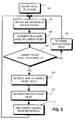
- a technique for selecting when to end a current interval and begin a new one is now described with reference to Figure 5.
- an initial value is assigned to a "sliding delay base" variable dm .
- This initial value is not critical because, as will become apparent below, after a short period of time its value will adjust to the properties of communications channel 2. Its value might be set, e.g., to the raw delay of the first packet received, to a function of such raw delay or to a value selected based on historical trends.
- the raw delay RawDelay i of a received packet i preferably is defined as the difference between the time that the packet is received by receiver 50 and the timestamp that was included within the packet by the transmitter.
- the raw delay of a packet generally does not have meaning as an absolute value; only the difference between raw delays does.
- the transmitter should add the same arbitrary value to all timestamps in the current session.
- the sliding delay base roughly can be defined as the minimum raw delay for some period of time.
- the recurrent way in which it is calculated in the preferred embodiments of the invention is discussed in more detail below.
- step 103 a new packet is received and its raw delay RawDelay i is identified. Again, this value preferably is determined by simply subtracting the embedded timestamp from the time that the packet was received.
- the sliding delay base is incremented based on the current packet.
- the increment in the sliding delay base is based on the difference between the reception time for the current packet and the reception time for the previously received packet. More preferably, the delay base increases linearly at a constant rate between received packets.
- dm i dT / TCr + dm i - 1 , where dm i is the new value of the delay base; dT is the difference in receive time (alternatively, the difference in transmit times may be used instead) between the current packet and a previous one that was the last used for updating the dm value; TCr is a behavioral parameter that defines the time interval needed for the sliding base dm to rise 1 ms if no smaller raw delay was encountered; and dm i-1 is the value of the previous delay base.
- the TCr value preferably is less than 1000 (assuming that dT is expressed in milliseconds) in order to accommodate possible differences between the transmit and receive clocks (which might be up to 0.1 % off).
- the better network condition the larger the value of TCr can be used. Values in the interval from 100 to 1000 appear to be reasonable.
- a value like 240 can be considered as a default value.
- step 107 a determination is made as to whether the new raw packet delay RawDelay i is less than or equal to the current delay base dm i . If not, then processing proceeds to step 108 in order to determine the relative packet delay for the new packet (discussed below), before returning to step 103 to receive and process of the next packet. On the other hand, if the determination in step 107 is answered in the affirmative, then the packet may be referred to as a "floor packet"; and processing proceeds to step 109 based on the identification of a new floor packet.
- the processing preferably is identical in steps 108 and 110. More preferably, the relative packet delay for the new packet RelativeDelay i is determined as the difference between the raw delay RawDelay i and the sliding delay base dm i for a given packet i . This calculation should be performed after the sliding delay base adjustment, if any, is done for the subject packet in step 109. As a result, the relative packet delay can never be negative. If the relative packet delay is 0, then the packet is referred to as a "floor packet".
- step 111 the current packet is deemed to be the last packet in the current interval (i.e., because of the determination made in step 107). That current interval can then be processed, e.g., in accordance with the technique described above in connection with Figure 4.
- a new interval is deemed to have begun, i.e., using the raw delay of the current packet as the initial delay base dm for the new interval. Thereafter, processing returns to step 103 in order to receive and process the first packet for the new interval.
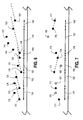
- Figure 6 shows a timeline of received packets 131-144, with the horizontal axis indicating the time of receipt for each of packets 131-144, and with the vertical axis indicating the raw packet delay for such packet.
- Figure 7 illustrates a timeline of recommended jitter buffer delays 171-177, with the horizontal axis indicating time and being aligned with the horizontal axis in Figure 6, and with the vertical axis indicating the recommended jitter buffer delay at that point in time.
- the sliding delay base dm begins at a point indicated by the raw delay of received packet 131 and increases linearly until it exceeds the raw delay of a subsequently received packet 133, at which point packet 133 is designated as a floor packet (marking the end of interval 151 and the beginning of the next interval 152), and the value of the sliding delay base dm is reset to the raw delay of packet 133. This process repeats over time, ultimately defining intervals 151-156.
- the recommended buffer delay Rdly is adjusted, as shown in Figure 7, starting from an initial value 171.
- the interval delay 181 (which in the present embodiment is the maximum relative delay during interval 151) is provided by packet 132.
- Interval delay 181 clearly is larger than the currently recommended buffer delay Rdly 171. Accordingly, recommended delay 171 is increased by RDLY_BIG_BUMP, to a value 172.
- interval delay 182 (provided by packet 134) is equal to the currently recommended buffer delay Rdly 172. Accordingly, recommended delay 172 is increased by RDLY_SMALL_BUMP, to a value 173.
- interval 153 the interval delay 183 (provided by packet 137) is less than the currently recommended buffer delay Rdly 173. Accordingly, recommended delay 173 is linearly decreased over the duration of interval 153, to a value 174. The process is repeated to provide subsequent recommended buffer delays Rdly 175-177.
- Interval selection tends to automatically provide updates to the recommended buffer delay at times when updates to the actual buffer delay would be appropriate. For instance, as shown in Figure 6, a new interval (e.g., interval 155) typically will start when there is a fairly sudden increase in the delay times of received packets. Because the sliding delay base increases over time, such a new interval will continue until the packet delays have dropped to a more typical value, until the increased packet delays have been continuing for a sufficiently long period of time, or some combination of the foregoing criteria. In either case, the jitter buffer 4 likely will be depleted or near depleted by the time that the recommended buffer delay is increased. As a result, increasing the actual buffer delay at that point typically will not provide significantly more degradation than already will be occurring as a result of the increased in delays in communications channel 2.
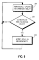
- the present invention also contemplates implementations in which the recommended delay does not become effective until a more appropriate time, such as when there is detected with a pause in the audio stream. Such a technique is described in more detail with reference to Figure 8.
- step 201 the recommended buffer delay periodically is updated. This step may be performed, e.g., in accordance with the techniques described above in connection with Figures 4 and 5 above.
- step 203 a determination is made as to whether or not the present time is appropriate for modifying the actual buffer delay.
- increasing buffer delay typically will result in a temporary pause in the output audio stream
- decreasing buffer delay typically will necessitate discarding some of the packets in the jitter buffer 4.
- neither case can be easily accommodated if there is a natural pause in the transmitted audio. That is, neither increasing the duration of such a pause (when increasing buffer delay) nor discarding audio data which is simply silence (when decreasing buffer delay) typically will be very noticeable during the occurrence of such a pause.
- increasing or decreasing buffer delay will not be very noticeable in the context of the surrounding circumstances, e.g., where the buffer 4 is already depleted of data packets to read out.
- periods of silence or pause may be indicated by the transmitter if it is operating in DTX mode.
- the receiver itself might detect such periods, e.g., by detecting a packet or a sequence of packets that have a volume level below a specified threshold.
- step 203 If the test of a step 203 is not satisfied, then processing returns to step 201 to continue updating the recommended buffer delay. On the other hand, if the test is satisfied then processing proceeds to step 204, in which the actual buffer delay is modified based upon the recommended delay. In certain embodiments of the invention, any such modification may be limited in scope. For example, if it is recommended to decrease the buffer delay in an amount equivalent to 80 packets and only 60 "silence" packets are detected, then adjustment of the actual delay might be limited to dropping only the 60 "silent" packets.
- Such a computer typically will include, for example, at least some of the following components interconnected with each other, e.g., via a common bus: one or more central processing units (CPUs), read-only memory (ROM), random access memory (RAM), input/output software and/or circuitry for interfacing with other devices and for connecting to one or more networks (which in turn may connect to the Internet or to any other networks), a display (such as a cathode ray tube display, a liquid crystal display, an organic light-emitting display, a polymeric light-emitting display or any other thin-film display), other output devices (such as one or more speakers, a headphone set and/or a printer), one or more input devices (such as a mouse, touchpad, tablet, touch-sensitive display or other pointing device; a keyboard, a microphone and/or a scanner), a mass storage unit (such as a hard disk drive), a real-
- CPUs central processing units
- ROM read-only memory
- RAM random access memory
- Suitable computers for use in implementing the present invention may be obtained from various vendors. Various types of computers, however, may be used depending upon the size and complexity of the tasks. Suitable computers include mainframe computers, multiprocessor computers, workstations, personal computers, and even smaller computers such as PDAs, wireless telephones or any other appliance or device, whether stand-alone, hard-wired into a network or wirelessly connected to a network.
- a general-purpose computer system has been described above, a special-purpose computer may also be used.
- any of the functionality described above can be implemented in software, hardware, firmware or any combination of these, with the particular implementation being selected based on known engineering tradeoffs.
- the present invention also relates to machine-readable media on which are stored program instructions for performing the methods of this invention.
- Such media include, by way of example, magnetic disks, magnetic tape, optically readable media such as CD ROMs and DVD ROMs, semiconductor memory such as PCMCIA cards, etc.
- the medium may take the form of a portable item such as a small disk, diskette, cassette, etc., or it may take the form of a relatively larger or immobile item such as a hard disk drive, ROM or RAM provided in a computer.
- parameters that define the behavior of the jitter buffer there are several parameters that define the behavior of the jitter buffer. These parameters preferably are selected based on the particular network conditions (e.g., the quality of the network or other communications channel 2). It does not appear that changing these parameters from the nominal values suggested above dramatically will improve the behavior of the jitter buffer, but undesirable results might be produced if such values are chosen unreasonably (e.g., significantly outside of the ranges indicated above).
- buffer delay is modified at discrete points in time.
- the embodiments described above contemplate a "discharging" of the jitter buffer delay, in which the recommended delay is effectively decreased on a continuous, monotonic and gradual basis until bumped up based upon a detection that an interval delay (or similar observation of packet delay) satisfies some specified criterion (e.g., an underflow condition).
- some specified criterion e.g., an underflow condition
- the technique for selecting intervals in the preferred embodiments of the invention often inherently tend to provide good time points for modifying the actual buffer delay. For example, by waiting until the increase in packet delay times has continued for a sufficient period of time, the packet delay times (according to any desired criteria) have decreased to an acceptable level, or any combination of the foregoing, the change often will occur when a pause would have happened anyway. Similar techniques that achieve similar results instead may be utilized.
- a decision might be made not to increase the recommended buffer delay at this time, but instead to store the information and make a decision later, e.g., if additional groups of packets with long delays are encountered. Then, if it is determined that groups of longer-delayed packets will continue to be received on a regular basis (e.g., because certain groups of packets take a different path through the communications channel 2), at that point the recommended buffer delay may be increased. Alternatively, if a determination ultimately is made that the single group of longer-delayed packets was a true anomaly, then the decision not to increase the jitter buffer delay at that time would have been the correct decision.
- functionality may be ascribed to a particular module or component. However, unless any particular functionality is described above as being critical to the referenced module or component, functionality may be redistributed as desired among any different modules or components, in some cases completely obviating the need for a particular component or module and/or requiring the addition of new components or modules.
- the precise distribution of functionality preferably is made according to known engineering tradeoffs, with reference to the specific embodiment of the invention, as will be understood by those skilled in the art.
Landscapes
- Engineering & Computer Science (AREA)
- Computer Networks & Wireless Communication (AREA)
- Signal Processing (AREA)
- Multimedia (AREA)
- Computer Hardware Design (AREA)
- Data Exchanges In Wide-Area Networks (AREA)
- Transmission Systems Not Characterized By The Medium Used For Transmission (AREA)
- Telephone Function (AREA)
- Communication Control (AREA)
Applications Claiming Priority (1)
| Application Number | Priority Date | Filing Date | Title |
|---|---|---|---|
| US10/981,163 US20060092918A1 (en) | 2004-11-04 | 2004-11-04 | Audio receiver having adaptive buffer delay |
Publications (2)
| Publication Number | Publication Date |
|---|---|
| EP1655911A2 true EP1655911A2 (de) | 2006-05-10 |
| EP1655911A3 EP1655911A3 (de) | 2006-06-07 |
Family
ID=35717709
Family Applications (1)
| Application Number | Title | Priority Date | Filing Date |
|---|---|---|---|
| EP05256493A Withdrawn EP1655911A3 (de) | 2004-11-04 | 2005-10-20 | Audioempfänger mit adaptiver Pufferverzögerung |
Country Status (3)
| Country | Link |
|---|---|
| US (1) | US20060092918A1 (de) |
| EP (1) | EP1655911A3 (de) |
| JP (1) | JP2006135974A (de) |
Cited By (5)
| Publication number | Priority date | Publication date | Assignee | Title |
|---|---|---|---|---|
| WO2007110692A1 (en) * | 2006-03-29 | 2007-10-04 | Sony Ericsson Mobile Communications Ab | Method and system for managing audio data |
| WO2008023302A1 (en) * | 2006-08-22 | 2008-02-28 | Nokia Corporation | Discontinuous transmission of speech signals |
| EP1919137A1 (de) * | 2006-10-30 | 2008-05-07 | Nokia Siemens Networks Gmbh & Co. Kg | Verfahren zur Leistungsbewertung von einem Jitter-Puffer |
| GB2518410A (en) * | 2013-09-20 | 2015-03-25 | Sony Comp Entertainment Europe | Entertainment Device and Method |
| US20190014050A1 (en) * | 2017-07-07 | 2019-01-10 | Qualcomm Incorporated | Apparatus and method for adaptive de-jitter buffer |
Families Citing this family (25)
| Publication number | Priority date | Publication date | Assignee | Title |
|---|---|---|---|---|
| TWI305101B (en) * | 2006-03-10 | 2009-01-01 | Ind Tech Res Inst | Method and apparatus for dynamically adjusting playout delay |
| US8121115B2 (en) * | 2006-07-10 | 2012-02-21 | Telefonaktiebolaget Lm Ericsson (Publ) | Compressed delay packet transmission scheduling |
| JP4629633B2 (ja) * | 2006-08-18 | 2011-02-09 | 三菱電機株式会社 | リアルタイム通話装置 |
| US20080170562A1 (en) * | 2007-01-12 | 2008-07-17 | Accton Technology Corporation | Method and communication device for improving the performance of a VoIP call |
| US8085803B2 (en) * | 2007-01-29 | 2011-12-27 | Intel Corporation | Method and apparatus for improving quality of service for packetized voice |
| US8566695B2 (en) * | 2007-03-30 | 2013-10-22 | Sandisk Technologies Inc. | Controlling access to digital content |
| US8027267B2 (en) * | 2007-11-06 | 2011-09-27 | Avaya Inc | Network condition capture and reproduction |
| CN101911550B (zh) * | 2008-03-27 | 2014-01-08 | 松下北美公司美国分部松下汽车系统公司 | 用于单调谐器系统的使fm调谐器灵敏度动态适应于本地环境的方法 |
| US8406715B2 (en) * | 2008-03-27 | 2013-03-26 | Panasonic Automotive Systems of America, division of Panasonic Corporation of North America | Method and apparatus for dynamically adapting FM tuner sensitivity to a local environment for a single-tuner system |
| JP5223444B2 (ja) * | 2008-05-01 | 2013-06-26 | 富士通株式会社 | 通信システム及び呼制御装置 |
| US8611337B2 (en) * | 2009-03-31 | 2013-12-17 | Adobe Systems Incorporated | Adaptive subscriber buffering policy with persistent delay detection for live audio streams |
| US9838784B2 (en) | 2009-12-02 | 2017-12-05 | Knowles Electronics, Llc | Directional audio capture |
| US9210503B2 (en) * | 2009-12-02 | 2015-12-08 | Audience, Inc. | Audio zoom |
| US8798290B1 (en) | 2010-04-21 | 2014-08-05 | Audience, Inc. | Systems and methods for adaptive signal equalization |
| US9558755B1 (en) | 2010-05-20 | 2017-01-31 | Knowles Electronics, Llc | Noise suppression assisted automatic speech recognition |
| US20140082504A1 (en) * | 2012-09-14 | 2014-03-20 | Kevin B. Stanton | Continuous data delivery with energy conservation |
| US9508345B1 (en) | 2013-09-24 | 2016-11-29 | Knowles Electronics, Llc | Continuous voice sensing |
| US9953634B1 (en) | 2013-12-17 | 2018-04-24 | Knowles Electronics, Llc | Passive training for automatic speech recognition |
| US9437188B1 (en) | 2014-03-28 | 2016-09-06 | Knowles Electronics, Llc | Buffered reprocessing for multi-microphone automatic speech recognition assist |
| WO2016040885A1 (en) | 2014-09-12 | 2016-03-17 | Audience, Inc. | Systems and methods for restoration of speech components |
| CN107210824A (zh) | 2015-01-30 | 2017-09-26 | 美商楼氏电子有限公司 | 麦克风的环境切换 |
| US10686897B2 (en) | 2016-06-27 | 2020-06-16 | Sennheiser Electronic Gmbh & Co. Kg | Method and system for transmission and low-latency real-time output and/or processing of an audio data stream |
| CN110351595B (zh) * | 2019-07-17 | 2023-08-18 | 北京百度网讯科技有限公司 | 一种缓冲处理方法、装置、设备和计算机存储介质 |
| CN110620793B (zh) * | 2019-10-31 | 2022-03-15 | 苏州浪潮智能科技有限公司 | 一种提高音频质量的方法、设备及介质 |
| GB2610801A (en) * | 2021-07-28 | 2023-03-22 | Stude Ltd | A system and method for audio recording |
Family Cites Families (8)
| Publication number | Priority date | Publication date | Assignee | Title |
|---|---|---|---|---|
| EP0921666A3 (de) * | 1997-12-02 | 1999-07-14 | Nortel Networks Corporation | Sprachempfang über eine Paketübertragungseinrichtung |
| US6859460B1 (en) * | 1999-10-22 | 2005-02-22 | Cisco Technology, Inc. | System and method for providing multimedia jitter buffer adjustment for packet-switched networks |
| US6683889B1 (en) * | 1999-11-15 | 2004-01-27 | Siemens Information & Communication Networks, Inc. | Apparatus and method for adaptive jitter buffers |
| US6862298B1 (en) * | 2000-07-28 | 2005-03-01 | Crystalvoice Communications, Inc. | Adaptive jitter buffer for internet telephony |
| US6757292B2 (en) * | 2001-07-11 | 2004-06-29 | Overture Networks, Inc. | Automatic adjustment of buffer depth for the correction of packet delay variation |
| US7006511B2 (en) * | 2001-07-17 | 2006-02-28 | Avaya Technology Corp. | Dynamic jitter buffering for voice-over-IP and other packet-based communication systems |
| US7079486B2 (en) * | 2002-02-13 | 2006-07-18 | Agere Systems Inc. | Adaptive threshold based jitter buffer management for packetized data |
| US20040129309A1 (en) * | 2003-01-07 | 2004-07-08 | Eckert Mark T. | Pneumatic wheel and tire overpressure protection method and apparatus |
-
2004
- 2004-11-04 US US10/981,163 patent/US20060092918A1/en not_active Abandoned
-
2005
- 2005-10-20 EP EP05256493A patent/EP1655911A3/de not_active Withdrawn
- 2005-11-01 JP JP2005318033A patent/JP2006135974A/ja active Pending
Cited By (9)
| Publication number | Priority date | Publication date | Assignee | Title |
|---|---|---|---|---|
| WO2007110692A1 (en) * | 2006-03-29 | 2007-10-04 | Sony Ericsson Mobile Communications Ab | Method and system for managing audio data |
| US7634227B2 (en) | 2006-03-29 | 2009-12-15 | Sony Ericsson Mobile Communications Ab | Method and system for controlling audio data playback in an accessory device |
| WO2008023302A1 (en) * | 2006-08-22 | 2008-02-28 | Nokia Corporation | Discontinuous transmission of speech signals |
| US7573907B2 (en) | 2006-08-22 | 2009-08-11 | Nokia Corporation | Discontinuous transmission of speech signals |
| EP1919137A1 (de) * | 2006-10-30 | 2008-05-07 | Nokia Siemens Networks Gmbh & Co. Kg | Verfahren zur Leistungsbewertung von einem Jitter-Puffer |
| GB2518410A (en) * | 2013-09-20 | 2015-03-25 | Sony Comp Entertainment Europe | Entertainment Device and Method |
| GB2518410B (en) * | 2013-09-20 | 2015-10-28 | Sony Comp Entertainment Europe | Entertainment Device and Method |
| US20190014050A1 (en) * | 2017-07-07 | 2019-01-10 | Qualcomm Incorporated | Apparatus and method for adaptive de-jitter buffer |
| US10616123B2 (en) * | 2017-07-07 | 2020-04-07 | Qualcomm Incorporated | Apparatus and method for adaptive de-jitter buffer |
Also Published As
| Publication number | Publication date |
|---|---|
| EP1655911A3 (de) | 2006-06-07 |
| JP2006135974A (ja) | 2006-05-25 |
| US20060092918A1 (en) | 2006-05-04 |
Similar Documents
| Publication | Publication Date | Title |
|---|---|---|
| EP1655911A2 (de) | Audioempfänger mit adaptiver Pufferverzögerung | |
| US7881284B2 (en) | Method and apparatus for dynamically adjusting the playout delay of audio signals | |
| US7630409B2 (en) | Method and apparatus for improved play-out packet control algorithm | |
| US8279884B1 (en) | Integrated adaptive jitter buffer | |
| US7162418B2 (en) | Presentation-quality buffering process for real-time audio | |
| EP1440375B1 (de) | Netzwerk-media-playout | |
| US7319703B2 (en) | Method and apparatus for reducing synchronization delay in packet-based voice terminals by resynchronizing during talk spurts | |
| US7499472B2 (en) | Jitter buffer management | |
| US7450601B2 (en) | Method and communication apparatus for controlling a jitter buffer | |
| US20020052967A1 (en) | Method and apparatus for providing continuous playback or distribution of audio and audio-visual streamed multimedia received over networks having non-deterministic delays | |
| JP4462996B2 (ja) | パケット受信方法及びパケット受信装置 | |
| US20050094622A1 (en) | Method and apparatus providing smooth adaptive management of packets containing time-ordered content at a receiving terminal | |
| CN103888381A (zh) | 用于控制抖动缓冲器的装置和方法 | |
| US20020064171A1 (en) | Dynamic delay compensation for packet-based voice network | |
| JP2007511939A5 (de) | ||
| US6785230B1 (en) | Audio transmission apparatus | |
| CN101002430B (zh) | 流数据接收播放装置及流数据接收播放方法 | |
| CN100512423C (zh) | 补偿报文分组时延变化的系统和方法 | |
| KR20040017228A (ko) | Ip 전화를 위한 동적 지연 관리 | |
| US7908147B2 (en) | Delay profiling in a communication system | |
| US7983309B2 (en) | Buffering time determination | |
| JP4376165B2 (ja) | 受信装置,クロック調整方法および放送システム | |
| US7650422B2 (en) | Audio playback apparatus for controlling pause and resume of audio | |
| KR20080012920A (ko) | 무선 통신 디바이스의 적응적 폴링을 위한 방법 및 장치 | |
| US7921242B1 (en) | Fibre channel elastic FIFO delay controller and loop delay method having a FIFO threshold transmission word adjuster for controlling data transmission rate |
Legal Events
| Date | Code | Title | Description |
|---|---|---|---|
| PUAI | Public reference made under article 153(3) epc to a published international application that has entered the european phase |
Free format text: ORIGINAL CODE: 0009012 |
|
| PUAL | Search report despatched |
Free format text: ORIGINAL CODE: 0009013 |
|
| AK | Designated contracting states |
Kind code of ref document: A2 Designated state(s): AT BE BG CH CY CZ DE DK EE ES FI FR GB GR HU IE IS IT LI LT LU LV MC NL PL PT RO SE SI SK TR |
|
| AX | Request for extension of the european patent |
Extension state: AL BA HR MK YU |
|
| AK | Designated contracting states |
Kind code of ref document: A3 Designated state(s): AT BE BG CH CY CZ DE DK EE ES FI FR GB GR HU IE IS IT LI LT LU LV MC NL PL PT RO SE SI SK TR |
|
| AX | Request for extension of the european patent |
Extension state: AL BA HR MK YU |
|
| AKX | Designation fees paid | ||
| REG | Reference to a national code |
Ref country code: DE Ref legal event code: 8566 |
|
| STAA | Information on the status of an ep patent application or granted ep patent |
Free format text: STATUS: THE APPLICATION IS DEEMED TO BE WITHDRAWN |
|
| 18D | Application deemed to be withdrawn |
Effective date: 20061208 |