EP1656511B1 - Interface entre le disque et la partie centrale de freins a disque - Google Patents
Interface entre le disque et la partie centrale de freins a disque Download PDFInfo
- Publication number
- EP1656511B1 EP1656511B1 EP04749210A EP04749210A EP1656511B1 EP 1656511 B1 EP1656511 B1 EP 1656511B1 EP 04749210 A EP04749210 A EP 04749210A EP 04749210 A EP04749210 A EP 04749210A EP 1656511 B1 EP1656511 B1 EP 1656511B1
- Authority
- EP
- European Patent Office
- Prior art keywords
- disc
- brake
- teeth
- central part
- tooth
- Prior art date
- Legal status (The legal status is an assumption and is not a legal conclusion. Google has not performed a legal analysis and makes no representation as to the accuracy of the status listed.)
- Expired - Lifetime
Links
- 238000006073 displacement reaction Methods 0.000 claims description 19
- 230000014509 gene expression Effects 0.000 description 8
- 238000004519 manufacturing process Methods 0.000 description 6
- 230000035945 sensitivity Effects 0.000 description 3
- 239000012141 concentrate Substances 0.000 description 1
- 230000007797 corrosion Effects 0.000 description 1
- 238000005260 corrosion Methods 0.000 description 1
- 230000001788 irregular Effects 0.000 description 1
- 239000000725 suspension Substances 0.000 description 1
Images





Classifications
-
- F—MECHANICAL ENGINEERING; LIGHTING; HEATING; WEAPONS; BLASTING
- F16—ENGINEERING ELEMENTS AND UNITS; GENERAL MEASURES FOR PRODUCING AND MAINTAINING EFFECTIVE FUNCTIONING OF MACHINES OR INSTALLATIONS; THERMAL INSULATION IN GENERAL
- F16D—COUPLINGS FOR TRANSMITTING ROTATION; CLUTCHES; BRAKES
- F16D65/00—Parts or details
- F16D65/02—Braking members; Mounting thereof
- F16D65/12—Discs; Drums for disc brakes
-
- F—MECHANICAL ENGINEERING; LIGHTING; HEATING; WEAPONS; BLASTING
- F16—ENGINEERING ELEMENTS AND UNITS; GENERAL MEASURES FOR PRODUCING AND MAINTAINING EFFECTIVE FUNCTIONING OF MACHINES OR INSTALLATIONS; THERMAL INSULATION IN GENERAL
- F16D—COUPLINGS FOR TRANSMITTING ROTATION; CLUTCHES; BRAKES
- F16D65/00—Parts or details
- F16D65/02—Braking members; Mounting thereof
- F16D2065/13—Parts or details of discs or drums
- F16D2065/134—Connection
- F16D2065/1356—Connection interlocking
- F16D2065/1368—Connection interlocking with relative movement both radially and axially
Definitions
- the present invention concerns disc brakes. Even though the disc brakes have been developed for heavy-duty vehicles, a person skilled in the art realises that they may be used for any type of vehicle.
- the present invention is primarily directed to the situation when the brake is in a released condition.
- the type of disc brakes for which the present invention is developed has one or more brake discs, of which at least one is sliding in an axial direction.
- the brake discs are received on a central part, which may be a sleeve received on a hub, the hub itself or any other means arranged in connection with a wheel axle or the like.
- the sliding discs are received in a rotationally fixed or interlocked way on the central part but slidable in axial direction:
- the interface between discs and said central part may be in the form of teeth, splines or the like.
- the rotational interlocking is needed in order to transfer the braking forces from brake pads acting on the discs, via the central part to the wheel axle or the like.
- wheel axle is use in a broad sense to facilitate the description. In many vehicles there is no literal wheel axle, at least not for non-driving wheels. The wheels are often supported by some kind of struts etc. of a wheel suspension. Often the wheel is received on an axle stud.
- the present disc brakes having one or more sliding discs often rattle in released condition. This is due to the fact that the teeth or the like of the brake discs and the central part have contact faces being either straight or curved in a not optimum way and that there has to be a clearance in the interface. To assure a reliable sliding function it is necessary to have a considerable clearance in the interface between the central part and the brake discs, due to the fact that brakes often are exposed to dirt and corrosion. The clearance produces a minor displacement of the rotational centres of sleeve and disc, mainly in a vertical direction. Thus, the discs may be displaced a short distance in radial direction relative the central part. During rotation the displacement will change intermittently, which may lead to generation of vibrations and noise.
- the number of teeth in simultaneous contact is often one or two at each side of a vertical centre line. This small number of contacts may cause vibrations and noise at teeth change over also for teeth designed to avoid the situation with a changing radial displacement, due to unavoidable manufacturing imperfections.
- straight as used in this description is meant that the teeth faces, or the like, are not curved seen in the direction of the wheel axis, even though they may have different angles in relation to the circumference of the disc or the central part.
- WO 89/05924 shows a disc brake comprising a disc hub adapted to be mounted to a wheel.
- the disc brace comprises a plurality of annularly shaped discs and means for mounting the discs to the disc hub.
- the disc brake of the present invention has one or more brake discs, of which at least one is sliding on a central part.
- the sliding brake discs are received on the central part in form of a sleeve, a hub or the like by means of teeth, splines or any other means, giving an interface which is rotationally interlocked but axially sliding.
- each disc and the central part should be as constant as possible during rotation in a released position, i.e. rotation when the brake is not actuated.
- at least two teeth of each disc should be in contact with at least two teeth of the central part at each side of a vertical centre line.
- the angular length of the parts of the teeth faces expected to make contact during rotation in released position should exceed a certain length, depending on the number of teeth. To facilitate this description these parts are often referred to as contact parts. If properly designed the teeth should be curved in such a way that the tangent at the point of contact between the teeth is substantially horizontal.
- the interface between the disc(s) and the central part should ideally be such that the mutual vertical positions of the disc(s) and the central part do not change during rotation.
- the displacement between each disc and the central part should be constant or almost constant in a released position of the brake. Due to production imperfections etc. displacement is not always exactly constant, and that is reflected above with the use of the expression "almost constant”.
- the teeth are arc-faced, i.e. the contact faces of the teeth have the form of arcs seen in the direction of the wheel axis. Furthermore, the nominal clearance between the contact faces of the teeth of the disc(s) and the central part is almost constant over a certain angular length, i.e. the curve form of the teeth of the discs and the central part are almost identical for that angular length. Said angular length is the length of the parts of the teeth expected to make contact during rotation in released position, or contact parts as stated above. As used here "nominal clearance" is determined in a position with zero displacement of the rotational centres between the disc and the central part.
- the parts expected to make contact relates to a released position of the brake.
- different parts of the teeth faces may be in contact in released position and in a braking position.
- the arcs may have constant or varying radii.
- An arc with a constant radius is a single circle arc, while an arc with varying radius will have a curve form differing from a single circle arc, thus it may have a regular or irregular curve form.
- the exact form of the curves of the teeth may vary as long as the desired conditions are satisfied.
- the angular length of the contact parts of each tooth of each disc and the central part, respectively is at least equal to the teeth pitch angle. If the angular length of the contact parts of each tooth is at least twice the teeth pitch angle, the number of teeth in simultaneous contact will be two or more at each side of a vertical centre line. The increased number of contacts reduces vibrations and noise at teeth change over, because the sensitivity to manufacturing imperfections is reduced.
- the angular length of the contact parts of the teeth exceeds 90°, preferably close to 180°, the theoretical number of simultaneous teeth contacts will be large and in the region of 25 to 50% of the total number of teeth. This large number of contacts reduces the vibrations and noise even more as the sensitivity to manufacturing imperfections will be very low. The wear resistance will be improved too.
- One object of the present invention is that the level of vibrations and thus, noise should be reduced in the released condition of the brake.
- a further object of the present invention is to improve the wear resistance in the interface between the brake discs and the central part. Still a further object is to reduce the sensitivity to manufacture tolerances and imperfections.
- a disc brake having a caliper receiving one or more brake pads and encircling one or more brake discs is arranged. At least one of the brake discs is received sliding on a central part in the form of a hub, a sleeve or the like. The central part is received on a wheel axle or the like.
- the discs are connected to the central part in a rotationally interlocked but axially sliding way by means of teeth, splines or the like. At least contact parts of the teeth and/or splines of the at least one disc and/or the central part have the form of arcs, seen in the direction of the wheel axis.
- the contact parts are the parts of the teeth faces expected to make contact with each other in a released position of the brake.
- Fig. 1 one example of a disc brake is shown.
- a person skilled in the art realises that the principles of the present invention apply for disc brakes having many different structures. Only parts important for the understanding of the present invention will be specifically referred to in the description below.
- the disc brake as shown has a caliper 1 surrounding two brake discs 2 received on a central part 3, here in the form of a hub.
- the brake discs 2 have teeth 4 on an inner circumference, which teeth 4 are to mesh with teeth 5 on the outer circumference of the central part 3.
- Brake pads 8 are received slidable in the caliper 1 in a normal way.
- the brake pads 8 are applied by means of a thrust plate 6 and a brake mechanism 7, received in the caliper 1.
- Braking torque is transferred from the discs 2 to the central part 3 by means of the teeth 4, 5 and/or splines of the brake discs 2 and central part 3, respectively.
- helical teeth or splines may be used.
- helical splines on a central part co-operates with brake disc(s) having straight-faced teeth.
- the discs 2 are received giving an interlocked interface in rotational direction but a sliding interface in axial direction.
- other number of discs 2 are used and one disc 2 may be fixed in axial direction.
- Brake pads 8 are placed on both sides of each brake discs 2. Also the brake pads 8 are received moveable in axial direction in the caliper 1, even though the brake pad 8 furthest from the thrust plate may be fixed. During braking the brake mechanism 7 will press the thrust plate 6 against the adjacent brake pad 8, which will be pressed against the brake disc 2 and so on. Braking will occur as the brake pads 8 and brake discs 2 are pressed against each other.
- the present invention is concerned with the situation when the brake is in a released condition.
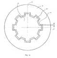
- the disc 9 With the rotating disc 9 and central part 10 in the position of Fig. 2a the disc 9 usually drop the distance s, corresponding to the clearance.
- the centres of rotation for the disc 9 and central part 10, respectively will usually be displaced mainly in a vertical direction, as shown in Fig. 2b .
- Said contact will normally be held until the disc 9 and central part 10 have rotated to a position in which the teeth in contact is at an angle of about 22,5° in relation to a horizontal line, as shown in Fig. 2c .
- the angle of 22.5° is due to the number of teeth in the shown example.
- the magnitude of said varying displacement might be reduced, by arranging the teeth and/or splines to be not parallel to the rotational axis of the disc, giving helical teeth and/or splines.
- the faces of the teeth and/or splines may be straight or arc formed. It enables a particular tooth or spline to provide a horizontal contact face during a determined interval of angular rotation of the disc. It concentrates the contact to a point moving axially along the tooth or spline during rotation.
- the most preferred design is the arc shaped contact faces described below, as they avoid the above varying displacement combined with maintaining a contact over a considerable length in axial direction.
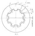
- the teeth 4, 5 and/or splines of the disc 2 and the central part 3 have contact faces in the form of arcs with constant or varying radii. Furthermore, the nominal clearance between the contact faces of the teeth of the disc(s) and the central part is almost constant over a certain angular length, i.e. the contact part. The nominal clearance is determined in a position with zero displacement of the rotational centres between the disc 2 and the central part 3, and in an angular position with approximately the same clearance on the right and left side of an individual tooth.
- the curved form may be a circle arc or be an arc with a spiral form, thus, having varying radii.
- the arc may go over the top with the same form or it may be two arcs merging into each other at the top. Thus, in some cases there is one arc form at the left tooth face and another arc form at the right tooth face.
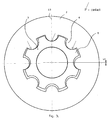
- the teeth 4, 5 of the disc 2 and central part 3, respectively, may have different combinations of convex and concave forms.
- the shown teeth forms are only some examples and a person skilled in the art realises that the form may vary in many further ways.
- parts of the teeth faces are straight, however the clearance must be big enough to avoid contact for the straight parts in a released position for the brake. In a braking position they may make contact.
- the parts of the teeth placed outside the contact parts in released position may have varying clearance.
- the form of the contact parts of the teeth is such that in each point of contact between the teeth 4, 5 of each disc 2 and the central part 3, respectively, the tangents of the arcs of the teeth 4, 5 are virtually horizontal.
- the number of teeth 4, 5 and/or splines does also influence the vibration and noise level.
- An increased number of teeth 4, 5 will give reduced vibrations and noise.
- the angular length of the contact parts having an arced shape and an almost constant nominal clearance at each tooth 4, 5, is of importance regarding reduction of vibrations and noise.
- each teeth 4, 5 of the discs 2 and the central part 3, respectively should have an accumulated angular length of the arced contact parts larger than 360°/Z, preferably larger than 2(360°/Z), where Z is the number of teeth 4, 5. If this angular length is even larger, the number of teeth in simultaneous contact increases.
- accumulated angular length refers to the angular length of the contact part of one tooth. If the arc has a varying radius said accumulated angular length is composed of several separate angular lengths, in principal one for each radius.
Landscapes
- Engineering & Computer Science (AREA)
- General Engineering & Computer Science (AREA)
- Mechanical Engineering (AREA)
- Braking Arrangements (AREA)
Claims (16)
- Frein à disque comportant un étrier (1) recevant une ou plusieurs plaquettes de frein (8) et encerclant un ou plusieurs disques de frein (2), dont au moins un disque de frein (2) est reçu coulissant sur une partie centrale (3) sous forme de moyeu, manchon ou analogue, laquelle partie centrale (3) est reçue sur un essieu de roue, l'au moins un disque de frein (2) étant relié à la partie centrale (3) de manière enclenchée en rotation mais coulissante axialement au moyen de dents (4, 5) ou cannelures, caractérisé en ce qu'au moins des parties de contact des dents (4, 5) ou cannelures de l'au moins un disque (2) et/ou de la partie centrale (3) présentent la forme d'arcs, vues dans la direction de l'axe de roue, lesquelles parties de contact sont les parties des dents prévues pour entrer en contact les unes avec les autres lors de la rotation dans une position relâchée du frein, et que les parties de contact des dents (4, 5) ou cannelures de chaque disque (2) et de la partie centrale (3) présentent un espace nominal entre le disque (2) et la partie centrale (3) qui est constant sans aucun déplacement entre le disque (2) et la partie centrale (3) et que les parties de contact sur chaque dent (4, 5) ou cannelure de chaque disque (2) et/ou de la partie centrale (3) présentent la forme d'arcs avec un angle d'arc accumulé supérieur à 360°/2, où Z est le nombre de dents (4, 5) du disque (2) et de la partie centrale (3), respectivement.
- Frein à disque selon la revendication 1, caractérisé en ce qu'au moins deux paires de dents ou cannelures de chaque disque (2) et la partie centrale (3) sont en contact, de chaque côté d'une ligne centrale verticale (13).
- Frein à disque selon la revendication 2, caractérisé en ce que la tangente de chaque point de contact (7) entre les dents (4, 5) ou cannelures du/des disque(s) de frein (2) et de la partie centrale (3) est sensiblement horizontale dans une position relâchée du frein.
- Frein à disque selon la revendication 1, caractérisé en ce que les arcs possèdent des rayons constants ou variés.
- Frein à disque selon la revendication 1, caractérisé en ce que les parties de contact sur chaque dent (4, 5) et/ou cannelure de chaque disque (2) et/ou de la partie centrale (3) présentent la forme d'arcs avec un angle d'arc accumulé supérieur à 2(360°/Z), où Z est le nombre de dents (4, 5) du disque (2) et de la partie centrale (3), respectivement.
- Frein à disque selon la revendication 1, caractérisé en ce que les parties de contact sur les dents (4, 5) de l'au moins un disque (2) et de la partie centrale (3) présentent la forme d'arcs avec un angle d'arc accumulé dépassant 20°, de préférence dépassant un angle d'arc de 30° et de façon préférée entre toutes dépassant un angle d'arc de 40°.
- Frein à disque selon la revendication 1, caractérisé en ce que la face de contact sur chaque dent (4, 5) est formée d'un arc allant du pied sur un côté de la dent (4, 5) au pied sur l'autre côté de la dent (4, 5).
- Frein à disque selon la revendication 1, caractérisé en ce que la face de contact sur chaque dent (4, 5) est formée de deux arcs, chaque arc allant du pied respectif sur des côtés opposés de la dent (4, 5) à la pointe de la dent (4, 5).
- Frein à disque selon la revendication 1, caractérisé en ce que les formes d'arc des dents (4, 5) sont identiques dans les parties de contact de chaque disque (2) et de la partie centrale (3), c'est-à-dire les parties qu'un point de contact suivra dans une position relâchée du frein.
- Frein à disque selon la revendication 1, caractérisé en ce que les dents et/ou cannelures du/des disque(s) et/ou de la partie centrale sont agencées de manière hélicoïdale, c'est-à-dire avec un angle contre l'axe de rotation desdites parties.
- Disque de frein (2) destiné à être utilisé dans un frein à disque selon l'une quelconque des revendications précédentes, caractérisé en ce qu'au moins des parties de contact des dents (4) ou cannelures du disque de frein (2) présentent la forme d'arcs, vues dans la direction d'un axe de roue, que les arcs possèdent des rayons constants ou variés et que les parties de contact sur chaque dent (4) ou cannelure du disque de frein (2) présentent la forme d'arcs avec un angle d'arc accumulé supérieur à 360°/Z, où Z est le nombre de dents (4) du disque de frein (2).
- Disque de frein (2) selon la revendication 11, caractérisé en ce que les parties de contact sur chaque dent (4) ou cannelure du disque de frein (2) présentent la forme d'arcs avec un angle d'arc accumulé supérieur à 2(360°/Z).
- Disque de frein (2) selon la revendication 11, caractérisé en ce que les parties de contact sur les dents (4, 5) ou cannelures du disque de frein (2) présentent la forme d'arcs avec un angle d'arc accumulé dépassant 20°, de préférence dépassant un angle d'arc de 30° et de façon préférée entre toutes dépassant un angle d'arc de 40°.
- Disque de frein (2) selon la revendication 11, caractérisé en ce que la face de contact sur chaque dent (4) ou cannelure est formée d'un arc allant du pied sur un côté de la dent (4) ou cannelure au pied sur l'autre côté de la dent (4) ou cannelure.
- Disque de frein (2) selon la revendication 11, caractérisé en ce que la face de contact sur chaque dent (4) ou cannelure est formée de deux arcs, chaque arc allant du pied respectif sur des côtés opposés de la dent (4) ou cannelure à la pointe de la dent (4) ou cannelure.
- Disque de frein (2) selon la revendication 11, caractérisé en ce que les dents ou cannelures du disque de frein (2) sont agencées de manière hélicoïdale, c'est-à-dire avec un angle contre l'axe de rotation du disque de frein (2).
Applications Claiming Priority (2)
| Application Number | Priority Date | Filing Date | Title |
|---|---|---|---|
| SE0302257A SE526555C2 (sv) | 2003-08-21 | 2003-08-21 | Gränssnitt mellan skiva och central del för skivbromsar |
| PCT/SE2004/001210 WO2005019678A1 (fr) | 2003-08-21 | 2004-08-18 | Interface entre le disque et la partie centrale de freins a disque |
Publications (2)
| Publication Number | Publication Date |
|---|---|
| EP1656511A1 EP1656511A1 (fr) | 2006-05-17 |
| EP1656511B1 true EP1656511B1 (fr) | 2009-10-07 |
Family
ID=28450271
Family Applications (1)
| Application Number | Title | Priority Date | Filing Date |
|---|---|---|---|
| EP04749210A Expired - Lifetime EP1656511B1 (fr) | 2003-08-21 | 2004-08-18 | Interface entre le disque et la partie centrale de freins a disque |
Country Status (9)
| Country | Link |
|---|---|
| US (1) | US7188711B2 (fr) |
| EP (1) | EP1656511B1 (fr) |
| CN (1) | CN100385135C (fr) |
| AT (1) | ATE445109T1 (fr) |
| BR (1) | BRPI0413612A (fr) |
| DE (1) | DE602004023520D1 (fr) |
| RU (1) | RU2349808C2 (fr) |
| SE (1) | SE526555C2 (fr) |
| WO (1) | WO2005019678A1 (fr) |
Cited By (2)
| Publication number | Priority date | Publication date | Assignee | Title |
|---|---|---|---|---|
| DE102009056075A1 (de) * | 2009-11-30 | 2011-06-09 | Iprotec Maschinen- Und Edelstahlprodukte Gmbh | Radbaugruppe |
| DE102017125867A1 (de) | 2017-11-06 | 2019-05-09 | Knorr-Bremse Systeme für Nutzfahrzeuge GmbH | Nachstelleinrichtung einer Scheibenbremse |
Families Citing this family (11)
| Publication number | Priority date | Publication date | Assignee | Title |
|---|---|---|---|---|
| SE526551C2 (sv) * | 2003-04-29 | 2005-10-04 | Haldex Brake Prod Ab | Placering av bromsok |
| EP1726517A1 (fr) * | 2005-05-27 | 2006-11-29 | Campagnolo Srl | Profile de couplage asymétrique entre un axe d'un pédalier d'une bicyclette et une manivelle de pédalier |
| DE602006002384D1 (de) * | 2006-07-05 | 2008-10-02 | Haldex Brake Prod Ab | Scheibenbremse und Abstandselement |
| US7854301B2 (en) * | 2007-06-22 | 2010-12-21 | Golden Lion Enterprise Co., Ltd. | Fixing and combining device for the brake disc of a remote-controlled model car |
| DE102008046546B4 (de) * | 2008-09-10 | 2013-01-17 | Daimler Ag | Bremsscheibe mit Bremsscheibentopf |
| DE102011011004A1 (de) * | 2011-02-11 | 2012-08-16 | Daimler Ag | Verbundbremsscheibe |
| USD771540S1 (en) * | 2015-06-15 | 2016-11-15 | Saf-Holland, Inc. | Brake spider |
| US9845861B1 (en) * | 2016-05-26 | 2017-12-19 | GM Global Technology Operations LLC | Rotatable assembly including a coupling interface |
| KR101897367B1 (ko) | 2016-12-01 | 2018-09-13 | 현대자동차주식회사 | 브레이크 디스크 |
| CN114370470B (zh) * | 2021-12-02 | 2023-02-03 | 河北艾斯特车桥有限公司 | 盘式制动器的导向传力结构 |
| CN116624528B (zh) * | 2023-01-12 | 2026-03-17 | 德翼高科(杭州)科技有限公司 | 碳陶制动盘及其制备方法 |
Citations (3)
| Publication number | Priority date | Publication date | Assignee | Title |
|---|---|---|---|---|
| FR1152328A (fr) * | 1956-06-13 | 1958-02-14 | Rech Etudes Production Sarl | Dispositif pour le montage des disques de frein sur leur moyeu d'entraînement |
| WO1989005924A1 (fr) * | 1987-12-18 | 1989-06-29 | Allied-Signal Inc. | Frein a double disque |
| WO2001098681A1 (fr) * | 2000-06-21 | 2001-12-27 | Haldex Brake Products Ab | Frein a disque(s) a contact ponctuel avec etrier fixe |
Family Cites Families (7)
| Publication number | Priority date | Publication date | Assignee | Title |
|---|---|---|---|---|
| SU889958A1 (ru) * | 1980-04-07 | 1981-12-15 | Воронежское Производственное Объединение По Выпуску Кузнечно-Прессового Оборудования Им.М.И.Калинина | Муфта-тормоз |
| FR2497307B1 (fr) * | 1980-12-29 | 1986-03-14 | Dba | Systeme de freinage du type a disque de freinage coulissant et disque de freinage pour un tel freinage |
| FR2548302B1 (fr) * | 1983-06-30 | 1985-10-25 | Dba | Frein multidisque perfectionne |
| US5213437A (en) * | 1988-12-10 | 1993-05-25 | Zahnradfabrik Friedrichshafen, Ag | Serrated-shaft connection |
| US5046596A (en) * | 1990-03-27 | 1991-09-10 | Harley-Davidson, Inc. | Methods and apparatus for controlling the frictional engagement between a hub and a shaft at a power transmission interface |
| SE504775C2 (sv) * | 1995-08-16 | 1997-04-21 | Volvo Ab | Hjulnav- och bromsskiveanordning för tunga motorfordon |
| GB9625862D0 (en) * | 1996-12-12 | 1997-01-29 | T & N Technology Ltd | Disc brake |
-
2003
- 2003-08-21 SE SE0302257A patent/SE526555C2/sv not_active IP Right Cessation
-
2004
- 2004-08-18 BR BRPI0413612-8A patent/BRPI0413612A/pt not_active IP Right Cessation
- 2004-08-18 RU RU2006108804/11A patent/RU2349808C2/ru not_active IP Right Cessation
- 2004-08-18 CN CNB2004800240743A patent/CN100385135C/zh not_active Expired - Fee Related
- 2004-08-18 WO PCT/SE2004/001210 patent/WO2005019678A1/fr not_active Ceased
- 2004-08-18 AT AT04749210T patent/ATE445109T1/de not_active IP Right Cessation
- 2004-08-18 DE DE602004023520T patent/DE602004023520D1/de not_active Expired - Lifetime
- 2004-08-18 EP EP04749210A patent/EP1656511B1/fr not_active Expired - Lifetime
- 2004-08-23 US US10/924,065 patent/US7188711B2/en not_active Expired - Fee Related
Patent Citations (3)
| Publication number | Priority date | Publication date | Assignee | Title |
|---|---|---|---|---|
| FR1152328A (fr) * | 1956-06-13 | 1958-02-14 | Rech Etudes Production Sarl | Dispositif pour le montage des disques de frein sur leur moyeu d'entraînement |
| WO1989005924A1 (fr) * | 1987-12-18 | 1989-06-29 | Allied-Signal Inc. | Frein a double disque |
| WO2001098681A1 (fr) * | 2000-06-21 | 2001-12-27 | Haldex Brake Products Ab | Frein a disque(s) a contact ponctuel avec etrier fixe |
Cited By (3)
| Publication number | Priority date | Publication date | Assignee | Title |
|---|---|---|---|---|
| DE102009056075A1 (de) * | 2009-11-30 | 2011-06-09 | Iprotec Maschinen- Und Edelstahlprodukte Gmbh | Radbaugruppe |
| DE102017125867A1 (de) | 2017-11-06 | 2019-05-09 | Knorr-Bremse Systeme für Nutzfahrzeuge GmbH | Nachstelleinrichtung einer Scheibenbremse |
| DE102017125867B4 (de) | 2017-11-06 | 2022-05-25 | Knorr-Bremse Systeme für Nutzfahrzeuge GmbH | Nachstelleinrichtung einer Scheibenbremse |
Also Published As
| Publication number | Publication date |
|---|---|
| RU2006108804A (ru) | 2006-07-10 |
| DE602004023520D1 (de) | 2009-11-19 |
| RU2349808C2 (ru) | 2009-03-20 |
| BRPI0413612A (pt) | 2006-10-17 |
| CN1839270A (zh) | 2006-09-27 |
| US7188711B2 (en) | 2007-03-13 |
| ATE445109T1 (de) | 2009-10-15 |
| SE526555C2 (sv) | 2005-10-04 |
| SE0302257L (sv) | 2005-02-22 |
| EP1656511A1 (fr) | 2006-05-17 |
| WO2005019678A1 (fr) | 2005-03-03 |
| CN100385135C (zh) | 2008-04-30 |
| US20050056498A1 (en) | 2005-03-17 |
| SE0302257D0 (sv) | 2003-08-21 |
Similar Documents
| Publication | Publication Date | Title |
|---|---|---|
| US7188711B2 (en) | Disc to central part interface for disc brakes | |
| CN1082459C (zh) | 用于重型汽车的轮毂与制动盘装置 | |
| US8474580B2 (en) | Floating brake disc | |
| TWI748054B (zh) | 用於自行車的制動盤 | |
| WO2015009821A2 (fr) | Rotor de frein à disque perfectionné pour véhicules utilitaires lourds | |
| JP5523329B2 (ja) | トルクを伝達するためのカップリングエレメント及び該カップリングエレメントを備える駆動ユニット | |
| TWI750366B (zh) | 自行車制動盤組件 | |
| EP1112919A2 (fr) | Disque de frein d'une bicyclette muni de bras reliant une partie annulaire intérieure à une partie annulaire extérieure et tangents à un cercle effectif | |
| US7681698B2 (en) | Disc brake | |
| US6330937B1 (en) | Wheel hub and brake disc arrangement for heavy vehicles | |
| EP0096553B1 (fr) | Assemblages de disque pour freins | |
| CN107571957B (zh) | 用于自行车的制动盘 | |
| EP3523551B1 (fr) | Agencement de frein de roue | |
| WO2000009907A1 (fr) | Systeme de frein a disque | |
| US20030165354A1 (en) | Device with a shaft and with at least one hub mounted on said shaft, and method for producing said device | |
| US20060213732A1 (en) | Brake rotor with rotational degrees of freedom | |
| CN100507303C (zh) | 盘式制动器的制动钳 | |
| US5909785A (en) | Twin ramp brake pad reaction member | |
| US20260098569A1 (en) | Shaped Brake Disc | |
| GB1589002A (en) | Expander for internal shoe drum brakes | |
| EP0641951B1 (fr) | Tambour de frein pour un frein de véhicule | |
| JP2009513888A (ja) | 変速機用可変装置構成 | |
| WO2003004896A1 (fr) | Raccordement de disque de frein |
Legal Events
| Date | Code | Title | Description |
|---|---|---|---|
| PUAI | Public reference made under article 153(3) epc to a published international application that has entered the european phase |
Free format text: ORIGINAL CODE: 0009012 |
|
| 17P | Request for examination filed |
Effective date: 20060209 |
|
| AK | Designated contracting states |
Kind code of ref document: A1 Designated state(s): AT BE BG CH CY CZ DE DK EE ES FI FR GB GR HU IE IT LI LU MC NL PL PT RO SE SI SK TR |
|
| DAX | Request for extension of the european patent (deleted) | ||
| RIN1 | Information on inventor provided before grant (corrected) |
Inventor name: GRIPEMARK, JOAKIM Inventor name: KAELL, PATRIK Inventor name: STENSSON, GOERAN |
|
| 17Q | First examination report despatched |
Effective date: 20080520 |
|
| GRAP | Despatch of communication of intention to grant a patent |
Free format text: ORIGINAL CODE: EPIDOSNIGR1 |
|
| GRAS | Grant fee paid |
Free format text: ORIGINAL CODE: EPIDOSNIGR3 |
|
| GRAA | (expected) grant |
Free format text: ORIGINAL CODE: 0009210 |
|
| AK | Designated contracting states |
Kind code of ref document: B1 Designated state(s): AT BE BG CH CY CZ DE DK EE ES FI FR GB GR HU IE IT LI LU MC NL PL PT RO SE SI SK TR |
|
| REG | Reference to a national code |
Ref country code: GB Ref legal event code: FG4D |
|
| REG | Reference to a national code |
Ref country code: CH Ref legal event code: EP |
|
| REG | Reference to a national code |
Ref country code: IE Ref legal event code: FG4D |
|
| REF | Corresponds to: |
Ref document number: 602004023520 Country of ref document: DE Date of ref document: 20091119 Kind code of ref document: P |
|
| PG25 | Lapsed in a contracting state [announced via postgrant information from national office to epo] |
Ref country code: SI Free format text: LAPSE BECAUSE OF FAILURE TO SUBMIT A TRANSLATION OF THE DESCRIPTION OR TO PAY THE FEE WITHIN THE PRESCRIBED TIME-LIMIT Effective date: 20091007 |
|
| NLV1 | Nl: lapsed or annulled due to failure to fulfill the requirements of art. 29p and 29m of the patents act | ||
| PG25 | Lapsed in a contracting state [announced via postgrant information from national office to epo] |
Ref country code: FI Free format text: LAPSE BECAUSE OF FAILURE TO SUBMIT A TRANSLATION OF THE DESCRIPTION OR TO PAY THE FEE WITHIN THE PRESCRIBED TIME-LIMIT Effective date: 20091007 Ref country code: PT Free format text: LAPSE BECAUSE OF FAILURE TO SUBMIT A TRANSLATION OF THE DESCRIPTION OR TO PAY THE FEE WITHIN THE PRESCRIBED TIME-LIMIT Effective date: 20100208 Ref country code: ES Free format text: LAPSE BECAUSE OF FAILURE TO SUBMIT A TRANSLATION OF THE DESCRIPTION OR TO PAY THE FEE WITHIN THE PRESCRIBED TIME-LIMIT Effective date: 20100118 Ref country code: SE Free format text: LAPSE BECAUSE OF FAILURE TO SUBMIT A TRANSLATION OF THE DESCRIPTION OR TO PAY THE FEE WITHIN THE PRESCRIBED TIME-LIMIT Effective date: 20091007 |
|
| PG25 | Lapsed in a contracting state [announced via postgrant information from national office to epo] |
Ref country code: PL Free format text: LAPSE BECAUSE OF FAILURE TO SUBMIT A TRANSLATION OF THE DESCRIPTION OR TO PAY THE FEE WITHIN THE PRESCRIBED TIME-LIMIT Effective date: 20091007 |
|
| PG25 | Lapsed in a contracting state [announced via postgrant information from national office to epo] |
Ref country code: BE Free format text: LAPSE BECAUSE OF FAILURE TO SUBMIT A TRANSLATION OF THE DESCRIPTION OR TO PAY THE FEE WITHIN THE PRESCRIBED TIME-LIMIT Effective date: 20091007 Ref country code: AT Free format text: LAPSE BECAUSE OF FAILURE TO SUBMIT A TRANSLATION OF THE DESCRIPTION OR TO PAY THE FEE WITHIN THE PRESCRIBED TIME-LIMIT Effective date: 20091007 |
|
| PG25 | Lapsed in a contracting state [announced via postgrant information from national office to epo] |
Ref country code: RO Free format text: LAPSE BECAUSE OF FAILURE TO SUBMIT A TRANSLATION OF THE DESCRIPTION OR TO PAY THE FEE WITHIN THE PRESCRIBED TIME-LIMIT Effective date: 20091007 Ref country code: EE Free format text: LAPSE BECAUSE OF FAILURE TO SUBMIT A TRANSLATION OF THE DESCRIPTION OR TO PAY THE FEE WITHIN THE PRESCRIBED TIME-LIMIT Effective date: 20091007 Ref country code: BG Free format text: LAPSE BECAUSE OF FAILURE TO SUBMIT A TRANSLATION OF THE DESCRIPTION OR TO PAY THE FEE WITHIN THE PRESCRIBED TIME-LIMIT Effective date: 20100107 Ref country code: NL Free format text: LAPSE BECAUSE OF FAILURE TO SUBMIT A TRANSLATION OF THE DESCRIPTION OR TO PAY THE FEE WITHIN THE PRESCRIBED TIME-LIMIT Effective date: 20091007 Ref country code: DK Free format text: LAPSE BECAUSE OF FAILURE TO SUBMIT A TRANSLATION OF THE DESCRIPTION OR TO PAY THE FEE WITHIN THE PRESCRIBED TIME-LIMIT Effective date: 20091007 |
|
| PLBE | No opposition filed within time limit |
Free format text: ORIGINAL CODE: 0009261 |
|
| STAA | Information on the status of an ep patent application or granted ep patent |
Free format text: STATUS: NO OPPOSITION FILED WITHIN TIME LIMIT |
|
| PG25 | Lapsed in a contracting state [announced via postgrant information from national office to epo] |
Ref country code: CZ Free format text: LAPSE BECAUSE OF FAILURE TO SUBMIT A TRANSLATION OF THE DESCRIPTION OR TO PAY THE FEE WITHIN THE PRESCRIBED TIME-LIMIT Effective date: 20091007 Ref country code: SK Free format text: LAPSE BECAUSE OF FAILURE TO SUBMIT A TRANSLATION OF THE DESCRIPTION OR TO PAY THE FEE WITHIN THE PRESCRIBED TIME-LIMIT Effective date: 20091007 |
|
| 26N | No opposition filed |
Effective date: 20100708 |
|
| PG25 | Lapsed in a contracting state [announced via postgrant information from national office to epo] |
Ref country code: GR Free format text: LAPSE BECAUSE OF FAILURE TO SUBMIT A TRANSLATION OF THE DESCRIPTION OR TO PAY THE FEE WITHIN THE PRESCRIBED TIME-LIMIT Effective date: 20100108 |
|
| PG25 | Lapsed in a contracting state [announced via postgrant information from national office to epo] |
Ref country code: IT Free format text: LAPSE BECAUSE OF FAILURE TO SUBMIT A TRANSLATION OF THE DESCRIPTION OR TO PAY THE FEE WITHIN THE PRESCRIBED TIME-LIMIT Effective date: 20091007 Ref country code: MC Free format text: LAPSE BECAUSE OF NON-PAYMENT OF DUE FEES Effective date: 20100831 |
|
| REG | Reference to a national code |
Ref country code: CH Ref legal event code: PL |
|
| GBPC | Gb: european patent ceased through non-payment of renewal fee |
Effective date: 20100818 |
|
| PG25 | Lapsed in a contracting state [announced via postgrant information from national office to epo] |
Ref country code: LI Free format text: LAPSE BECAUSE OF NON-PAYMENT OF DUE FEES Effective date: 20100831 Ref country code: CH Free format text: LAPSE BECAUSE OF NON-PAYMENT OF DUE FEES Effective date: 20100831 |
|
| REG | Reference to a national code |
Ref country code: FR Ref legal event code: ST Effective date: 20110502 |
|
| PG25 | Lapsed in a contracting state [announced via postgrant information from national office to epo] |
Ref country code: IE Free format text: LAPSE BECAUSE OF NON-PAYMENT OF DUE FEES Effective date: 20100818 Ref country code: FR Free format text: LAPSE BECAUSE OF NON-PAYMENT OF DUE FEES Effective date: 20100831 |
|
| PG25 | Lapsed in a contracting state [announced via postgrant information from national office to epo] |
Ref country code: GB Free format text: LAPSE BECAUSE OF NON-PAYMENT OF DUE FEES Effective date: 20100818 |
|
| PGFP | Annual fee paid to national office [announced via postgrant information from national office to epo] |
Ref country code: DE Payment date: 20110808 Year of fee payment: 8 |
|
| PG25 | Lapsed in a contracting state [announced via postgrant information from national office to epo] |
Ref country code: CY Free format text: LAPSE BECAUSE OF FAILURE TO SUBMIT A TRANSLATION OF THE DESCRIPTION OR TO PAY THE FEE WITHIN THE PRESCRIBED TIME-LIMIT Effective date: 20091007 |
|
| PG25 | Lapsed in a contracting state [announced via postgrant information from national office to epo] |
Ref country code: HU Free format text: LAPSE BECAUSE OF FAILURE TO SUBMIT A TRANSLATION OF THE DESCRIPTION OR TO PAY THE FEE WITHIN THE PRESCRIBED TIME-LIMIT Effective date: 20100408 Ref country code: LU Free format text: LAPSE BECAUSE OF NON-PAYMENT OF DUE FEES Effective date: 20100818 |
|
| PG25 | Lapsed in a contracting state [announced via postgrant information from national office to epo] |
Ref country code: TR Free format text: LAPSE BECAUSE OF FAILURE TO SUBMIT A TRANSLATION OF THE DESCRIPTION OR TO PAY THE FEE WITHIN THE PRESCRIBED TIME-LIMIT Effective date: 20091007 |
|
| PG25 | Lapsed in a contracting state [announced via postgrant information from national office to epo] |
Ref country code: DE Free format text: LAPSE BECAUSE OF NON-PAYMENT OF DUE FEES Effective date: 20130301 |
|
| REG | Reference to a national code |
Ref country code: DE Ref legal event code: R119 Ref document number: 602004023520 Country of ref document: DE Effective date: 20130301 |