EP1656544B1 - Dispositif de centrifugation - Google Patents
Dispositif de centrifugation Download PDFInfo
- Publication number
- EP1656544B1 EP1656544B1 EP04731200A EP04731200A EP1656544B1 EP 1656544 B1 EP1656544 B1 EP 1656544B1 EP 04731200 A EP04731200 A EP 04731200A EP 04731200 A EP04731200 A EP 04731200A EP 1656544 B1 EP1656544 B1 EP 1656544B1
- Authority
- EP
- European Patent Office
- Prior art keywords
- base
- back plate
- slide
- pressure plate
- microscope slide
- Prior art date
- Legal status (The legal status is an assumption and is not a legal conclusion. Google has not performed a legal analysis and makes no representation as to the accuracy of the status listed.)
- Expired - Lifetime
Links
- 238000005119 centrifugation Methods 0.000 title claims description 29
- 239000000523 sample Substances 0.000 claims description 27
- 239000012530 fluid Substances 0.000 claims description 14
- 239000012472 biological sample Substances 0.000 claims description 5
- 239000007788 liquid Substances 0.000 claims description 5
- 238000007789 sealing Methods 0.000 claims description 5
- 239000000725 suspension Substances 0.000 claims description 2
- 210000004027 cell Anatomy 0.000 description 11
- 239000011521 glass Substances 0.000 description 3
- 238000004519 manufacturing process Methods 0.000 description 3
- 239000000463 material Substances 0.000 description 3
- 239000004033 plastic Substances 0.000 description 3
- 229920003023 plastic Polymers 0.000 description 3
- 239000004743 Polypropylene Substances 0.000 description 2
- 239000002250 absorbent Substances 0.000 description 2
- 230000000295 complement effect Effects 0.000 description 2
- 239000010410 layer Substances 0.000 description 2
- 230000002093 peripheral effect Effects 0.000 description 2
- -1 polypropylene Polymers 0.000 description 2
- 229920001155 polypropylene Polymers 0.000 description 2
- 230000000903 blocking effect Effects 0.000 description 1
- 210000003850 cellular structure Anatomy 0.000 description 1
- 238000004140 cleaning Methods 0.000 description 1
- 238000011109 contamination Methods 0.000 description 1
- 230000008021 deposition Effects 0.000 description 1
- 238000006073 displacement reaction Methods 0.000 description 1
- 230000000694 effects Effects 0.000 description 1
- 210000003811 finger Anatomy 0.000 description 1
- 238000001746 injection moulding Methods 0.000 description 1
- 238000000034 method Methods 0.000 description 1
- 239000002991 molded plastic Substances 0.000 description 1
- 238000000465 moulding Methods 0.000 description 1
- 238000003825 pressing Methods 0.000 description 1
- 230000000717 retained effect Effects 0.000 description 1
- 239000002356 single layer Substances 0.000 description 1
- 210000003813 thumb Anatomy 0.000 description 1
- 238000003466 welding Methods 0.000 description 1
Images



Classifications
-
- G—PHYSICS
- G01—MEASURING; TESTING
- G01N—INVESTIGATING OR ANALYSING MATERIALS BY DETERMINING THEIR CHEMICAL OR PHYSICAL PROPERTIES
- G01N1/00—Sampling; Preparing specimens for investigation
- G01N1/28—Preparing specimens for investigation including physical details of (bio-)chemical methods covered elsewhere, e.g. G01N33/50, C12Q
- G01N1/2813—Producing thin layers of samples on a substrate, e.g. smearing, spinning-on
-
- G—PHYSICS
- G01—MEASURING; TESTING
- G01N—INVESTIGATING OR ANALYSING MATERIALS BY DETERMINING THEIR CHEMICAL OR PHYSICAL PROPERTIES
- G01N1/00—Sampling; Preparing specimens for investigation
- G01N1/28—Preparing specimens for investigation including physical details of (bio-)chemical methods covered elsewhere, e.g. G01N33/50, C12Q
- G01N1/2813—Producing thin layers of samples on a substrate, e.g. smearing, spinning-on
- G01N2001/2846—Cytocentrifuge method
-
- Y—GENERAL TAGGING OF NEW TECHNOLOGICAL DEVELOPMENTS; GENERAL TAGGING OF CROSS-SECTIONAL TECHNOLOGIES SPANNING OVER SEVERAL SECTIONS OF THE IPC; TECHNICAL SUBJECTS COVERED BY FORMER USPC CROSS-REFERENCE ART COLLECTIONS [XRACs] AND DIGESTS
- Y10—TECHNICAL SUBJECTS COVERED BY FORMER USPC
- Y10T—TECHNICAL SUBJECTS COVERED BY FORMER US CLASSIFICATION
- Y10T436/00—Chemistry: analytical and immunological testing
- Y10T436/25—Chemistry: analytical and immunological testing including sample preparation
- Y10T436/25375—Liberation or purification of sample or separation of material from a sample [e.g., filtering, centrifuging, etc.]
-
- Y—GENERAL TAGGING OF NEW TECHNOLOGICAL DEVELOPMENTS; GENERAL TAGGING OF CROSS-SECTIONAL TECHNOLOGIES SPANNING OVER SEVERAL SECTIONS OF THE IPC; TECHNICAL SUBJECTS COVERED BY FORMER USPC CROSS-REFERENCE ART COLLECTIONS [XRACs] AND DIGESTS
- Y10—TECHNICAL SUBJECTS COVERED BY FORMER USPC
- Y10T—TECHNICAL SUBJECTS COVERED BY FORMER US CLASSIFICATION
- Y10T436/00—Chemistry: analytical and immunological testing
- Y10T436/25—Chemistry: analytical and immunological testing including sample preparation
- Y10T436/25375—Liberation or purification of sample or separation of material from a sample [e.g., filtering, centrifuging, etc.]
- Y10T436/255—Liberation or purification of sample or separation of material from a sample [e.g., filtering, centrifuging, etc.] including use of a solid sorbent, semipermeable membrane, or liquid extraction
-
- Y—GENERAL TAGGING OF NEW TECHNOLOGICAL DEVELOPMENTS; GENERAL TAGGING OF CROSS-SECTIONAL TECHNOLOGIES SPANNING OVER SEVERAL SECTIONS OF THE IPC; TECHNICAL SUBJECTS COVERED BY FORMER USPC CROSS-REFERENCE ART COLLECTIONS [XRACs] AND DIGESTS
- Y10—TECHNICAL SUBJECTS COVERED BY FORMER USPC
- Y10T—TECHNICAL SUBJECTS COVERED BY FORMER US CLASSIFICATION
- Y10T436/00—Chemistry: analytical and immunological testing
- Y10T436/25—Chemistry: analytical and immunological testing including sample preparation
- Y10T436/2575—Volumetric liquid transfer
Definitions
- THIS INVENTION relates to a centrifugation device comprising a combined sample chamber and slide holder adapted to be mounted, with a microscope slide, in a centrifuge in a predetermined position, after placing, in the sample chamber, a fluid biological sample containing cells, the device being so-arranged that when the centrifuge is operated, a thin layer - ideally a monolayer - of cells is deposited from the fluid onto a predetermined deposition area on the glass microscope slide.
- a centrifugation device is herein referred to as being "of the kind specifies”.
- centrifugation device of the kind specified have been known in the past. Examples of such devices are disclosed, for example, in US Patents 4,391,710 ; 4,696,743 ; 4,853,188 and 4,874,582 and European Patents Nos. 0184374 and 0047840 . Some examples have been reusable, that is to say it was possible and intended that after the device had been used to deposit cells from a fluid sample onto a first microscope slide, and the slide removed, the device could be cleaned, a fresh slide fitted, a fresh fluid sample placed in the sample chamber and the device again placed into the centrifuge and so on indefinitely. In these arrangements the slide is, of course retained by a releasable and re-attachable clip of some description.
- a centrifugation device of the kind specified generally comprises a combined sample chamber and slide holder adapted to be mounted, with a microscope slide, in a pre-determined position in a centrifuge after placing, in the sample chamber, a fluid biological sample containing cells, the centrifugation device comprising a body affording a base adapted for engagement with such microscope slide, structure on one side of the base defining the sample chamber with an opening for the introduction of fluid to the sample chamber, the base including an aperture for communicating with the sample chamber and the base carrying means for sealing the edges of such aperture with respect to the surface of the microscope slide placed across the base, or for allowing the passage of liquid but obstructing the passage of cells.
- Such a centrifugation device further typically includes, a back plate hingedly connected with the base, or otherwise securable to the base.
- the Applicant's have proposed, in co-pending UK Patent Application No. 0301047.7 to use an elastomeric gasket around said aperture to effect a seal with respect to the slide.
- a centrifugation devices comprising a combined sample chamber and slide holder adapted to be mounted, with a microscope slide, in a centrifuge in a predetermined position, after placing, in the sample chamber, a fluid biological sample containing cells
- the centrifugation device comprising a body affording a base adapted for engagement with a microscope slide, structure on one side of the base defining a chamber for a fluid sample, with an opening for the introduction of fluid to said chamber, the base including an aperture and carrying a means for sealing the edges of such aperture with respect to the surface of a microscope slide placed across the base, or for allowing the passage of liquid but.obstructing the passage of cells
- the centrifugation device further including a back plate arranged, when the back plate is closed against the rear of a microscope slide engaged with the base, to locate the slide between the base and the back plate and to hold the cover plate in this closed position
- said base comprises a supporting frame and, within said supporting frame, a pressure plate provided with
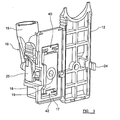
- a centrifugation device in accordance with the present invention comprises a body part 10 and a back plate 12 formed integrally with one another by moulding in a suitable plastics material such as polypropylene, the back plate 12 being connected with the body part 10 by way of an integral "living hinge" 22.
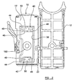
- the body part 10 comprises a base 14 which, as described below, comprises a frame 17 bounding a plate 19 which carries on its front side integral structure providing a sample chamber 16 which is closed at its end remote from the base 14 and which terminates, in the plane of the plate 19, in an aperture or port 18.
- a funnel 15 extends upwardly from an entrance opening in the sample chamber, whereby a fluid sample can be introduced into the sample chamber 16.
- the base 14 is generally rectangular, as is the back plate 12, and the living hinge 22 extends along one vertical edge of the base 14, more particularly along one vertical edge of the frame 17, and the adjacent vertical edge of the back plate 12.
- the vertical edge of the back plate 12 remote from the living hinge 22 carries a detent 24 for co-operating with elements 25 carried by the body 10 adjacent the edge of the base 14 remote from the living hinge 22 and which elements, together with detent 24, form a catch arrangement whereby the back plate may be secured in a closed position on the base 14 with a microscope slide, indicated at 26 in Figure 5, held between the base 14 and the back plate 12.
- a filter card 20 is fixed to the rear surface of frame 17 and extends over the plate 19.
- the filter card 20 comprises a sheet of liquid-absorbent card or paper, which is secured, for example, by ultrasonic welding, at its upper and lower ends, (as viewed in Figure 1) to the frame 17 and extends over the counter plate 19.
- the filter card 20 has an aperture 21 therein which corresponds in size, shape and position to the port 18 and is aligned therewith.
- a microscope slide 26 is located between the back plate 12 and the filter card on the base 14.
- Figures 1 to 3 show integral lugs 31 to support the lower end of a microscope slide 26 fitted against the front surface of the back plate 12 until the back plate 12, with the slide, is closed against the base 14).
- the device is then mounted in a centrifuge (not shown) in such a manner that bosses 30 projecting from the sides of the back plate act as journals receive in bearings provided by complementary slots in mounting structure within the centrifuge.
- a centrifuge (not shown)
- bosses 30 projecting from the sides of the back plate act as journals receive in bearings provided by complementary slots in mounting structure within the centrifuge.
- the device rests in the centrifuge in a position in which the slide 26 is at an angle.
- the device pivots about the axis of bosses 30, into a position in which the slide is vertical.
- the centrifugal force generated produces a rapid settling of the cells within the biological sample against the surface of the glass slide 26, within an area bounded by the edges of port 18 and the aperture 21 in the card 20 and these cells remain in a thin layer on the slide after the centrifuge is stopped.
- the centrifugation device is removed from the centrifuge, and the slide carefully removed after opening of the back plate.
- the catch arrangement 24,25 is preferably so devised, for example as described in our co-upending UK Patent Application GB0301047.7 , that the process of opening the back plate fractures part of the catch arrangement and ensures that the centrifugation device cannot be re-used.
- the base 14 comprises a peripheral frame 17 and a central panel or pressure plate 19 which is mounted with respect to the frame 17 in such a manner as to allow movement of the pressure plate 19 with respect to the frame 17:
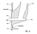
- Both the frame 17 and the pressure plate 19 have substantially planar rearwardly racing surfaces, i.e. surfaces which face away from the sample chamber 16, and in the unstressed condition of the pressure plate 19 and the mounting means therefor, the rear surface of the pressure plate is generally parallel with but spaced slightly rearwardly of the plane of the rear surface of the frame 17, as shown in Figure 4.
- the sample chamber 16 and funnel 15 are preferably substantially rigid with pressure plate 19 and can move slightly, with the pressure plate 19, relative to the peripheral frame 17.
- the slide in the closed condition of the device, in order to ensure that there is no gap between the filter card and the edge of the port 18 or between the filter card in the region around the aperture 21 and the slide 26, trough which the cell component of the sample as well as the liquid component might leak, the slide should bear evenly on the filter paper all around the periphery of apertures 21 and the part of the pressure plate around the aperture 18 should likewise bear evenly against the filter paper.
- the relevant parts of the pressure plate and the slide, and the portions of the back plate bearing against the slide should be substantially parallel with one another to achieve this condition.
- the pressure plate 19 is mounted within the frame 17 in such a way as to allow the pressure plate to "float" i.e. to adjust its position slightly in relation to the frame 17. As best shown in Figure 2, this is achieved as follows.
- the frame 17 takes the form of a generally rectangular plate which preferably has stiffening structures (not shown in detail), extending from and integral with the front of that plate, i.e. extending generally in the direction in which the sample chamber extends from the pressure plate.
- the pressure plate 19 and the support or suspension means therefor are mounted in a generally rectangular aperture 38 in the frame 17 by a respective torsion bar arrangement 40, 42 respectively at the upper or lower end of aperture 38, (as viewed in Figure 2), the pressure plate 19 having a profile complementary with that of the aperture 38 and being mounted with a generally uniform gap between the side edges of the pressure plate 19 and the adjacent edges of aperture 38 and with a larger gap, accommodating the respective torsion bar arrangement, between the upper edge of the plate 19 and the upper edge of the aperture 38 and between the lower edge of plate 19 and the lower edge of the aperture 38.
- each torsion bar arrangement comprises a first bar 44, adjacent the respective upper or lower edge of the aperture 38 and spanning the aperture 38 from one side edge of that aperture to the other, a second, parallel bar 46, spanning the space between two lugs 48 at the upper corners or two lugs 49 at the lower corners respectively of the pressure plate 19, and an intermediate web 50, much narrower than the pressure plate 19 and thus extending along only over a limited middle portion of the first and second bars 44, 46.
- the rear surface of the pressure plate 19 is, as previously noted, set rearwardly somewhat relatively to the rear surface of the frame 17. In this position, however, the rear surface of the pressure plate is still generally parallel with the rear surface of the frame 17.
- the pressure plate 19 is displaced forwardly relative to the frame 17 by the pressure applied by the back plate via the slide and the filter card, this displacement being permitted by resilient twisting and flexing of the torsion bars, particularly the longer torsion bars 44.
- Figure 6 illustrates a variant of the device of Figures 1 to 5 which differs from that of Figures 1 to 5 in that there are two sample chambers (not shown) terminating in respective apertures or ports 18a, 18b, in the pressure plate 19 and connected with respective funnels (defined by distinct and mutually isolated parts of a unitary funnel structure 15a).
- the variant of Figure 6 is intended to be used with a filter card (not shown) having respective apertures aligned with the ports 18a, 18b.
- the frame, pressure plate and torsion bar arrangements in the embodiments described are preferably formed in one piece, with the remainder of the centrifugation device, as a unitary injection moulding in a suitable plastics material such as polypropylene.
Landscapes
- General Health & Medical Sciences (AREA)
- Health & Medical Sciences (AREA)
- Life Sciences & Earth Sciences (AREA)
- Chemical & Material Sciences (AREA)
- Analytical Chemistry (AREA)
- Biochemistry (AREA)
- Physics & Mathematics (AREA)
- General Physics & Mathematics (AREA)
- Immunology (AREA)
- Pathology (AREA)
- Sampling And Sample Adjustment (AREA)
- Investigating Or Analysing Biological Materials (AREA)
- Centrifugal Separators (AREA)
Claims (3)
- Dispositif de centrifugation comprenant une chambre d'échantillon combinée (16) et un support coulissant adapté pour être monté, avec une lame porte-objet de microscope, dans une centrifugeuse dans une position prédéterminée, après mise en place, dans la chambre d'échantillon, d'un échantillon de fluide biologique contenant des cellules, le dispositif de centrifugation comprenant un corps (10) offrant une base (14) apte à la coopération avec une lame porte-objet de microscope, structure sur un côté de la base définissant une chambre (16) pour un échantillon de fluide, avec une ouverture pour l'introduction du fluide dans ladite chambre, la base comprenant une ouverture (18) et portant des moyens (20) pour rendre étanches les bords de sa couverture par rapport à la surface d'une lame porte-objet de microscope placée sur la base ou pour permettre le passage du liquide mais obstruant le passage des cellules, le dispositif de centrifugation comprenant de plus une plaque arrière (12) disposée, lorsque la plaque arrière (12) est fermée contre l'arrière d'une lame porte-objet de microscope coopérant avec la base (14), pour positionner la lame porte-objet entre la base et la plaque arrière (12) et pour maintenir la plaque arrière (12) dans cette position fermée, caractérisé en ce que ladite base (14) comprend un châssis de support (17) et, à l'intérieur dudit châssis de support (17), une plaque de pression (19) munie de ladite ouverture (18) et dans laquelle la plaque de pression (19) est supportée par ledit châssis (17) par des moyens élastiques souples (40, 42), de façon à permettre à la plaque de pression de "flotter" et de s'aligner sur une lame porte-objet de microscope située entre la plaque de pression (19) et la plaque arrière (12) lorsque la plaque arrière est fermée.
- Dispositif de centrifugation selon la revendication 1, dans lequel lesdits moyens de montage élastiques souples (40, 42) sont tels à permettre à la plaque de pression de basculer selon deux axes perpendiculaires entre eux, en général parallèles au plan du châssis (17), c'est-à-dire avec le plan des surfaces principales de cette lame porte-objet de microscope dans la position fermée du dispositif.
- Dispositif de centrifugation selon l'une quelconque des revendications précédentes, dans lequel lesdits moyens de suspension souples élastiques (40, 42) comprennent un agencement de barre de torsion moulée solidairement avec le reste du dispositif.
Applications Claiming Priority (2)
| Application Number | Priority Date | Filing Date | Title |
|---|---|---|---|
| GBGB0319709.2A GB0319709D0 (en) | 2003-08-21 | 2003-08-21 | A centrifugation device |
| PCT/GB2004/001904 WO2005019806A1 (fr) | 2003-08-21 | 2004-05-05 | Dispositif de centrifugation |
Publications (2)
| Publication Number | Publication Date |
|---|---|
| EP1656544A1 EP1656544A1 (fr) | 2006-05-17 |
| EP1656544B1 true EP1656544B1 (fr) | 2007-12-19 |
Family
ID=28460099
Family Applications (1)
| Application Number | Title | Priority Date | Filing Date |
|---|---|---|---|
| EP04731200A Expired - Lifetime EP1656544B1 (fr) | 2003-08-21 | 2004-05-05 | Dispositif de centrifugation |
Country Status (9)
| Country | Link |
|---|---|
| US (1) | US7575719B2 (fr) |
| EP (1) | EP1656544B1 (fr) |
| JP (1) | JP4393515B2 (fr) |
| CN (1) | CN100554923C (fr) |
| AU (1) | AU2004267535B2 (fr) |
| CA (1) | CA2534580C (fr) |
| DE (1) | DE602004010821T2 (fr) |
| GB (1) | GB0319709D0 (fr) |
| WO (1) | WO2005019806A1 (fr) |
Families Citing this family (7)
| Publication number | Priority date | Publication date | Assignee | Title |
|---|---|---|---|---|
| US7758816B2 (en) * | 2007-03-01 | 2010-07-20 | Wescor Inc. | Large area cytocentrifuge sample chamber |
| CN101246096B (zh) * | 2008-03-12 | 2010-08-11 | 郑明� | 离心制片机用吊篮及离心制片机 |
| US8257667B2 (en) | 2009-09-15 | 2012-09-04 | Biomedical Polymers, Inc. | Cytocentrifuge sample container holder and support device |
| US9739691B2 (en) | 2013-07-15 | 2017-08-22 | Cytogen Co., Ltd. | Slide assembly |
| CN109107775B (zh) * | 2017-06-26 | 2023-11-10 | 硅能光电半导体(广州)有限公司 | 一种led基板离心装置及其使用方法 |
| US11435267B1 (en) | 2022-06-14 | 2022-09-06 | Angle Europe Limited | Cell recovery method and device |
| JP2025520492A (ja) * | 2022-06-15 | 2025-07-03 | アングル・ユーロプ・リミテッド | 細胞回収方法および装置 |
Family Cites Families (4)
| Publication number | Priority date | Publication date | Assignee | Title |
|---|---|---|---|---|
| GB8514589D0 (en) * | 1985-06-10 | 1985-07-10 | Shandon Southern Prod | Centrifugation |
| US4853188A (en) * | 1985-11-14 | 1989-08-01 | Kabushiki Kaisha Tiyoda Seisakusho | Cell for placing solid matters on a slide glass under centrifugal force |
| US5470758A (en) * | 1994-12-14 | 1995-11-28 | Shandon, Inc. | Large cytology sample chamber for distributing material onto a microscope slide |
| US5952239A (en) * | 1997-06-12 | 1999-09-14 | Shandon, Inc. | Cytology chamber with port to receive collection bottle and method of use |
-
2003
- 2003-08-21 GB GBGB0319709.2A patent/GB0319709D0/en not_active Ceased
-
2004
- 2004-05-05 WO PCT/GB2004/001904 patent/WO2005019806A1/fr not_active Ceased
- 2004-05-05 AU AU2004267535A patent/AU2004267535B2/en not_active Expired
- 2004-05-05 CA CA2534580A patent/CA2534580C/fr not_active Expired - Lifetime
- 2004-05-05 JP JP2006523662A patent/JP4393515B2/ja not_active Expired - Lifetime
- 2004-05-05 US US10/569,705 patent/US7575719B2/en not_active Expired - Lifetime
- 2004-05-05 EP EP04731200A patent/EP1656544B1/fr not_active Expired - Lifetime
- 2004-05-05 DE DE602004010821T patent/DE602004010821T2/de not_active Expired - Lifetime
- 2004-05-05 CN CNB2004800239801A patent/CN100554923C/zh not_active Expired - Lifetime
Also Published As
| Publication number | Publication date |
|---|---|
| GB0319709D0 (en) | 2003-09-24 |
| US7575719B2 (en) | 2009-08-18 |
| JP2007502974A (ja) | 2007-02-15 |
| AU2004267535A1 (en) | 2005-03-03 |
| DE602004010821D1 (de) | 2008-01-31 |
| CA2534580A1 (fr) | 2005-03-03 |
| EP1656544A1 (fr) | 2006-05-17 |
| CA2534580C (fr) | 2014-04-22 |
| DE602004010821T2 (de) | 2008-04-10 |
| CN100554923C (zh) | 2009-10-28 |
| JP4393515B2 (ja) | 2010-01-06 |
| US20070003439A1 (en) | 2007-01-04 |
| WO2005019806A1 (fr) | 2005-03-03 |
| AU2004267535B2 (en) | 2009-01-22 |
| CN1839304A (zh) | 2006-09-27 |
Similar Documents
| Publication | Publication Date | Title |
|---|---|---|
| JP3459923B2 (ja) | 複数部位走化性試験装置及び方法 | |
| US4948564A (en) | Multi-well filter strip and composite assemblies | |
| US4895706A (en) | Multi-well filter strip and composite assemblies | |
| CA2817516C (fr) | Systeme multicompartiment pour le confinement de tissus a des fins de diagnostics moleculaires et histologiques | |
| EP1656544B1 (fr) | Dispositif de centrifugation | |
| EP0880021B1 (fr) | Assemblée de préparation centrifugale d'échantillons cytologiques | |
| EP0800571A2 (fr) | Dispositif d'analyse biologique a caracteristique de prevention de contamination amelioree | |
| JPH0418283B2 (fr) | ||
| KR20160061645A (ko) | 세포 도말장치용 멤브레인 필터용기 | |
| EP1380345B1 (fr) | Portoir à usage unique de récipients pour le traitement d'échantillons biologiques en cytocentrifuges | |
| US20080000827A1 (en) | Frameless, Plate-Shaped Filtering Member | |
| AU2003252996B2 (en) | Centrifugation device | |
| EP0205107B1 (fr) | Centrifugeuse | |
| CA2254119A1 (fr) | Analyseur d'echantillon | |
| JPS63202372A (ja) | 被検査体の瀘過装置 | |
| WO2025256966A1 (fr) | Cartouche microfluidique pour système de traitement d'échantillon biologique | |
| CN115916382A (zh) | 中空纤维膜组件 | |
| GB1596806A (en) | Chromatography tanks and tank inserts | |
| ITBO960337A1 (it) | Dispositivo per il supporto ed il contenimento di culture cellulari biologiche |
Legal Events
| Date | Code | Title | Description |
|---|---|---|---|
| PUAI | Public reference made under article 153(3) epc to a published international application that has entered the european phase |
Free format text: ORIGINAL CODE: 0009012 |
|
| 17P | Request for examination filed |
Effective date: 20060131 |
|
| AK | Designated contracting states |
Kind code of ref document: A1 Designated state(s): DE FR GB IT |
|
| DAX | Request for extension of the european patent (deleted) | ||
| RBV | Designated contracting states (corrected) |
Designated state(s): DE FR GB IT |
|
| 17Q | First examination report despatched |
Effective date: 20070302 |
|
| GRAP | Despatch of communication of intention to grant a patent |
Free format text: ORIGINAL CODE: EPIDOSNIGR1 |
|
| GRAS | Grant fee paid |
Free format text: ORIGINAL CODE: EPIDOSNIGR3 |
|
| GRAA | (expected) grant |
Free format text: ORIGINAL CODE: 0009210 |
|
| AK | Designated contracting states |
Kind code of ref document: B1 Designated state(s): DE FR GB IT |
|
| REG | Reference to a national code |
Ref country code: GB Ref legal event code: FG4D |
|
| REF | Corresponds to: |
Ref document number: 602004010821 Country of ref document: DE Date of ref document: 20080131 Kind code of ref document: P |
|
| ET | Fr: translation filed | ||
| PLBE | No opposition filed within time limit |
Free format text: ORIGINAL CODE: 0009261 |
|
| STAA | Information on the status of an ep patent application or granted ep patent |
Free format text: STATUS: NO OPPOSITION FILED WITHIN TIME LIMIT |
|
| 26N | No opposition filed |
Effective date: 20080922 |
|
| REG | Reference to a national code |
Ref country code: FR Ref legal event code: PLFP Year of fee payment: 12 |
|
| REG | Reference to a national code |
Ref country code: FR Ref legal event code: PLFP Year of fee payment: 13 |
|
| REG | Reference to a national code |
Ref country code: FR Ref legal event code: PLFP Year of fee payment: 14 |
|
| REG | Reference to a national code |
Ref country code: FR Ref legal event code: PLFP Year of fee payment: 15 |
|
| PGFP | Annual fee paid to national office [announced via postgrant information from national office to epo] |
Ref country code: IT Payment date: 20230519 Year of fee payment: 20 Ref country code: FR Payment date: 20230525 Year of fee payment: 20 Ref country code: DE Payment date: 20230530 Year of fee payment: 20 |
|
| PGFP | Annual fee paid to national office [announced via postgrant information from national office to epo] |
Ref country code: GB Payment date: 20230529 Year of fee payment: 20 |
|
| REG | Reference to a national code |
Ref country code: DE Ref legal event code: R071 Ref document number: 602004010821 Country of ref document: DE |
|
| REG | Reference to a national code |
Ref country code: GB Ref legal event code: PE20 Expiry date: 20240504 |
|
| PG25 | Lapsed in a contracting state [announced via postgrant information from national office to epo] |
Ref country code: GB Free format text: LAPSE BECAUSE OF EXPIRATION OF PROTECTION Effective date: 20240504 |
|
| PG25 | Lapsed in a contracting state [announced via postgrant information from national office to epo] |
Ref country code: GB Free format text: LAPSE BECAUSE OF EXPIRATION OF PROTECTION Effective date: 20240504 |