EP1656800B1 - System architecture method and computer program product for managing telecommunication networks - Google Patents
System architecture method and computer program product for managing telecommunication networks Download PDFInfo
- Publication number
- EP1656800B1 EP1656800B1 EP03818101A EP03818101A EP1656800B1 EP 1656800 B1 EP1656800 B1 EP 1656800B1 EP 03818101 A EP03818101 A EP 03818101A EP 03818101 A EP03818101 A EP 03818101A EP 1656800 B1 EP1656800 B1 EP 1656800B1
- Authority
- EP
- European Patent Office
- Prior art keywords
- architecture
- network
- layer
- management
- agents
- Prior art date
- Legal status (The legal status is an assumption and is not a legal conclusion. Google has not performed a legal analysis and makes no representation as to the accuracy of the status listed.)
- Expired - Lifetime
Links
- 238000000034 method Methods 0.000 title claims description 103
- 238000004590 computer program Methods 0.000 title claims description 3
- 230000008569 process Effects 0.000 claims description 79
- 238000007726 management method Methods 0.000 claims description 44
- 238000013499 data model Methods 0.000 claims description 18
- 230000009471 action Effects 0.000 claims description 15
- 230000006870 function Effects 0.000 claims description 15
- 238000005516 engineering process Methods 0.000 claims description 10
- 238000004891 communication Methods 0.000 claims description 6
- 238000012544 monitoring process Methods 0.000 claims description 6
- 238000012795 verification Methods 0.000 claims description 3
- 239000010410 layer Substances 0.000 description 56
- 101150012579 ADSL gene Proteins 0.000 description 15
- 102100020775 Adenylosuccinate lyase Human genes 0.000 description 15
- 108700040193 Adenylosuccinate lyases Proteins 0.000 description 15
- 238000010586 diagram Methods 0.000 description 9
- 230000000694 effects Effects 0.000 description 9
- 230000001419 dependent effect Effects 0.000 description 6
- 238000007792 addition Methods 0.000 description 5
- 238000013459 approach Methods 0.000 description 5
- 230000008859 change Effects 0.000 description 5
- 230000004048 modification Effects 0.000 description 5
- 238000012986 modification Methods 0.000 description 5
- 230000008901 benefit Effects 0.000 description 3
- 238000013461 design Methods 0.000 description 3
- 230000003993 interaction Effects 0.000 description 3
- 230000001360 synchronised effect Effects 0.000 description 3
- 102100035373 Cyclin-D-binding Myb-like transcription factor 1 Human genes 0.000 description 2
- 101000804518 Homo sapiens Cyclin-D-binding Myb-like transcription factor 1 Proteins 0.000 description 2
- 230000003542 behavioural effect Effects 0.000 description 2
- 238000011161 development Methods 0.000 description 2
- 230000018109 developmental process Effects 0.000 description 2
- 238000012545 processing Methods 0.000 description 2
- 238000001994 activation Methods 0.000 description 1
- 230000003044 adaptive effect Effects 0.000 description 1
- 238000004458 analytical method Methods 0.000 description 1
- 230000006399 behavior Effects 0.000 description 1
- 230000015556 catabolic process Effects 0.000 description 1
- 239000012141 concentrate Substances 0.000 description 1
- 238000005314 correlation function Methods 0.000 description 1
- 238000006731 degradation reaction Methods 0.000 description 1
- 230000001747 exhibiting effect Effects 0.000 description 1
- 238000000605 extraction Methods 0.000 description 1
- 238000009434 installation Methods 0.000 description 1
- 238000013507 mapping Methods 0.000 description 1
- 230000007246 mechanism Effects 0.000 description 1
- 230000005012 migration Effects 0.000 description 1
- 238000013508 migration Methods 0.000 description 1
- 230000007935 neutral effect Effects 0.000 description 1
- 238000005457 optimization Methods 0.000 description 1
- 230000000737 periodic effect Effects 0.000 description 1
- 230000002085 persistent effect Effects 0.000 description 1
- 230000001737 promoting effect Effects 0.000 description 1
- 230000009467 reduction Effects 0.000 description 1
- 238000009877 rendering Methods 0.000 description 1
- 230000011218 segmentation Effects 0.000 description 1
- 230000011664 signaling Effects 0.000 description 1
- 239000002356 single layer Substances 0.000 description 1
- 238000000638 solvent extraction Methods 0.000 description 1
- 230000002123 temporal effect Effects 0.000 description 1
- 230000001960 triggered effect Effects 0.000 description 1
Images




Classifications
-
- H—ELECTRICITY
- H04—ELECTRIC COMMUNICATION TECHNIQUE
- H04L—TRANSMISSION OF DIGITAL INFORMATION, e.g. TELEGRAPHIC COMMUNICATION
- H04L41/00—Arrangements for maintenance, administration or management of data switching networks, e.g. of packet switching networks
- H04L41/04—Network management architectures or arrangements
- H04L41/046—Network management architectures or arrangements comprising network management agents or mobile agents therefor
-
- H—ELECTRICITY
- H04—ELECTRIC COMMUNICATION TECHNIQUE
- H04L—TRANSMISSION OF DIGITAL INFORMATION, e.g. TELEGRAPHIC COMMUNICATION
- H04L41/00—Arrangements for maintenance, administration or management of data switching networks, e.g. of packet switching networks
- H04L41/04—Network management architectures or arrangements
- H04L41/042—Network management architectures or arrangements comprising distributed management centres cooperatively managing the network
-
- H—ELECTRICITY
- H04—ELECTRIC COMMUNICATION TECHNIQUE
- H04L—TRANSMISSION OF DIGITAL INFORMATION, e.g. TELEGRAPHIC COMMUNICATION
- H04L41/00—Arrangements for maintenance, administration or management of data switching networks, e.g. of packet switching networks
- H04L41/04—Network management architectures or arrangements
- H04L41/044—Network management architectures or arrangements comprising hierarchical management structures
-
- H—ELECTRICITY
- H04—ELECTRIC COMMUNICATION TECHNIQUE
- H04Q—SELECTING
- H04Q3/00—Selecting arrangements
- H04Q3/0016—Arrangements providing connection between exchanges
- H04Q3/0062—Provisions for network management
Definitions
- the invention relates to architectures for managing telecommunication networks and to services and tools for use in those architectures.
- FCAPS an acronym for Fault, Configuration, Accounting, Performance, Security
- US-A-6 243 396 proposes a multilayer architecture of authorities that includes agents. These agents are specialized for the various FCAPS functionalities as well as for representing network resources (proxy). This approach is quite flexible but fails to be truly satisfactory as regards the need of precisely identifying functionalities in the different layers and to avoid excessively layered structures likely to give rise to control and interfacing complexity.
- US-A-6 243 396 does describe distributed and hierarchical agents exchanging goals. However, layers are not specified in their functions.
- Process engines have also been proposed for use as workflow coordinators in distributed components each offering specific functionalities: see for example WO-A-01/02973 where the possibility is demonstrated of using a centralized workflow engine for coordinating distributed agents.
- the object of the present invention is thus to dispense with the intrinsic disadvantages of the prior art arrangements considered in the foregoing.
- the invention also relates to a corresponding method as well as computer program products loadable in the memory of at least one computer and comprising software code portions for performing the method of the invention.
- Reference to "at least one computer” is evidently intended to highlight the suitability for decentralized implementation of at least part of the arrangement of the invention.
- the arrangement described herein specifies a new platform for the distributed management of a telecommunication network and the services supported thereby as well as a manner for rendering the components very flexible and scalable.
- each layer will have a specific task: a first layer will support centralized/coordination functionalities, the second layer will support the distributed functionalities and the third layer proxies the network with the aim of decoupling network interfaces from management functions.
- the administrator of the platform will thus be in a position to generate any FCAPS functions by defining them in the data base, while the components involved will "learn” the new process definitions (workflow and rules) and run them when needed.
- Agent an agent is an independent and autonomous process with possible persistent state and requiring communication (e.g. collaboration or competition) with other agents in order to fulfill its tasks. This communication may be implemented through asynchronous message passing and by using well known languages (i.e. Agent Communication Language or ACL) with a well-defined and commonly agreed semantics.
- ACL Agent Communication Language
- Element Manager in a network management environment this is an application that manages a number of network elements.
- the element manager is developed by the network element vendor and includes functionalities like: configuration, alarm monitoring and service provisioning.
- OSS Operations Support System: in a network management environment this is the application that is in charge of running tasks like trouble ticketing, billing, order management. Typically OSSs support the service and network management applications.
- Network and service inventory this is the system that stores and makes inventory information available to the other OSSs or management applications.
- the inventory information may include network and computing equipment, logical resources, topology and services.
- This (sub)system keeps track of the physical and topology configuration of the network, equipment inventory (cards, ports, etc.), physical and logical connectivity of the different network layers.
- a portion of the inventory, usually called “catalog”, holds the descriptions of all entities stored in the inventory, both services and network entities.
- the Inventory keeps also track of planned, subscribed and provisioned services. Services are associated with the logical and physical network resources.
- Manager application this is an application running on a host and adapted to co-ordinate operation of one or more agents. It may include a graphical user interface (GUI) and is adapted to communicate with the distributed agents. For instance, it may distribute workflows, call the distributed agents to invoke an operation on a managed resource and perform administrative tasks.
- GUI graphical user interface
- Information model this is the collection of information related to all managed objects. This information is preferably arranged in information types (or categories), each of these being in turn related to a given type of managed object (e.g. a personal computer, and so on).
- a managed object is one of any number of specific characteristics of a managed device.
- managed devices are network elements and managed objects are entities like: cards, ports, physical and logical connections etc.
- Proxy a proxy object is a component mediating control of access to the actual object, for example a network element, on which a functionality lies.
- Rule engine is a system for separating business rules (logically and/or physically) from the control logic and sharing them across data stores, user interfaces and applications. Once the rules are separated out and shared, the rule engine allows the users to modify them without making changes to other application modules.
- a rule engine is basically a sophisticated if/then statement interpreter. The if/then statements that are interpreted are called rules. The 'if' portions of the rules contain conditions such as 'item.price > $100'. The 'then' portions of the rules contain actions such as "recommendDiscount (5%)'.
- the inputs to a rule engine are a rule set and some data objects. The outputs from a rule engine are determined by the inputs and may include the original input data objects with possible modifications, new data objects and side effects.
- a rule engine is used to decide, at runtime, which rules apply and how these are to be executed.
- a workflow is essentially the full or partial automation, e.g. of a business process, where documents, information or tasks are passed from one participant to another for action, according to a set of procedural rules.
- a workflow can be represented through a flowchart with a sequence of tasks and temporal and logical dependencies between tasks including alternative or parallel branches.
- a workflow can also be described as a finite state machine or with descriptive languages such as XPDL (XML Process Description Language).
- a workflow engine is the component in a workflow automation program that possesses all the information related to the procedures, steps in a procedure, and the rules for each step. The workflow engine determines whether the process is ready to move on to the next step.
- a workflow engine is a component adopted for executing workflows.
- the architecture in question (or platform) is adapted for managing a telecommunication network N including network equipments (not shown in detail but of any known type).
- control interfaces such as those indicated as if_N ⁇ , if_N w , if_N y , if_N t in figure 1 .
- the resource proxies RP1, ... ., RPn; RP1... ., RPm and the associated protocol adapters PA1, ...PAi; PA1, ... .Paj essentially comprise a base layer that proxies the interfaces if_N ⁇ , if_N w , if_N y , if_N t by decoupling them from management functions.
- the agents AAs in turn comprise a community of agents that co-ordinate operation of the base layer (RA, RP) in order to support distributed management functionalities.
- the base layer and the support layer constitute separated superposed layers in the architecture.
- the data base MDB is the single (logical) point of definition and storage of all the behavioral and functional aspects of the platform, workflows, rules, information models and schemes.
- the platform automatically distributes these definitions to the platform components.
- the model data base is strictly linked to the catalog part of the network inventory system.
- the MDB data base Being the source of all process and common data definition the MDB data base is inherently synchronized with the functionalities offered by the different components and the information models used to represent resources and services. This represents a major asset for the architecture operator who is not required to retrieve information from a huge amount of documentation provided by the different component vendors with the risk of failing to be aligned with all the operating components.
- processes are segmented into three layers with specific functions. This choice is intended to meet two needs: having the lowest possible number of layers (thus avoiding the complexity of conventional architectures) and allowing free allocation of processes between a distributed and a centralized implementation.
- a centralized layer 1 that corresponds to the manager application MA
- a fully distributed support layer 2 that corresponds to the agent applications - hereinafter, briefly, AAs
- one independent proxy layer 3 that decouples the network from the management platform.
- This segmentation also enables the provision of different service views, for example a business view by layer 1, a fulfillment view by layer 2 and an engineering view by layer 3. It will be appreciated that referring to the manager application MA and the layer comprised of the agent applications AAs does not exclude the possibility that the respective components may be at least partially arranged at the same geographical location.
- Protocol adapters are typically arranged in sets, each set being responsible for interfacing all the network equipments of a designated area that offer the same application programming interface (API) protocol, for example SNMP (Simple Network Management Protocol), Telnet, TL1, etc.
- API application programming interface
- Each PA offers, as a service rendered to the resource proxies RP, execution of basic operations on the equipment; example of services for a SNMP protocol adapter are: get(parameters), set(parameters).
- Each resource proxy (hereinafter, briefly, RP) is responsible for creating, maintaining and managing a so called "image" of a single equipment in the network N.
- the image is a representation of the configuration of the equipment according to a defined information model.
- the single equipment image can be enriched by element manager (EM) information such as e.g. inter-equipment information like topology, to give end-to-end view of services scattered across multiple equipments, and other information available on the EM.
- EM element manager
- PE process executor
- Examples of services offered by the RP are: configure port, create cross-connection, modify connection attribute; each of these can include sequences of basic commands to be sent and/or received to/by the equipments.
- Processes at the bottom of layer 3 use services offered by PAs.
- An example of a "layer 3" process is shown in figure 5 .
- the image handled by a RP is dynamically defined by the information model of the represented resource (e.g. a given network equipment).
- This model is defined by the GUI interface, stored in the data base MDB, then distributed by the manager application to the RPs. These load the model and finally instantiate it with values retrieved by the resource. Again the instantiation is performed in a flexible way using the PE.
- the network inventory CNI is arranged in two parts, namely: a distributed network inventory (DNI) and a centralized network inventory (CNI).
- DNI distributed network inventory
- CNI centralized network inventory
- the former i.e. the DNI
- the former is the collection of all virtualizations (images) contained in all the RPs; it is used for all real-time or almost real-time tasks as provisioning, assurance, performance, control, and so on, where updated information on the configuration and state of the network is necessary for the accuracy and effectiveness of the task.
- These real-time tasks are difficult to perform by relying upon a logically centralized database, as is the case in current implementations of network inventory.
- the latter part corresponds to the usual concept of a network inventory component. It is used for non real-time tasks where continuous updates are not possible for a centralized architecture. Example of such tasks are network design, network planning, capacity trend analysis.
- the centralized network inventory is periodically updated retrieving information from the RPs.
- Proxies can interact with one another directly for jobs that require simple inter-working. For example, in order to set up an end-to-end path, a given AA can use the topology information (which equipment is connected to which other) stored in the respective RPs.
- Each AA is responsible for coordination of a respective set of RPs and for the execution of processes typical of the agent layer by using a PE. These processes must be executed in a distributed way and can be structured in sub-layers. Processes at the top of this "layer 2" can be externally invoked; thus these are the services that an AA offers to the manager application MA. These services are characterized by being vendor and technology independent, for example "create a DSL service", resulting into different sequences of actions whether the network technology is ADSL or VDSL and whether the vendor is vendor XX or vendor YY. Processes at the bottom of layer 2 use services (that is, invoke processes) offered by RPs.
- Each AA does not require software update to support new services and technologies. This is due to the flexibility of the processes that are received by the manager application MA, loaded and executed by the AA layer.
- AAs interact with one another via a community protocol (a messaging passing mechanism) to support distributed execution of management functionalities, for example distributed circuit design.
- community protocol a messaging passing mechanism
- Each AA is responsible for local performance monitoring in order to inform the manager in respect of performance status.
- the manager application MA is responsible for the following tasks:
- Processes of such "layer 1" can be arranged in sub-layers and are characterized in order to provide functionalities that require interaction with external entities (other than AAs) or coordination among agents that cannot easily or efficiently be performed in a distributed way by AAs.
- the great flexibility of the architecture permits smooth evolution: for example, enhancement of the community protocol may enable migration of a process from layer 1 to layer 2.
- Process executors for any layer are intended to be a workflow (a flowchart), a rule engine, or a combination of the two.
- a provisioning process is better represented as a workflow while an alarm correlation is better represented as a combination of rules.
- This combination enables the administrator of the platform to set up any FCAPS functionality and let it evolve with a high degree of flexibility. Whenever possible and advisable, using workflows is preferred as this avoids the complexity of dealing with rule conflicts and rule management.
- the process engines are embedded within the MAs, AAs and RPs; in fact an external location would entail remote invocations likely to produce performance degradations.
- the various MAs, AAs and RPs show both a reactive and a proactive behaviour, as they are triggered on events but may also start processes.
- Each of the AAs and the RPs as well as the MA can support any FCAPS functionality. That enables task-customization of components and reallocation based on task priority and resource needs, e.g. by allotting a majority of agents during daytime to service provisioning and a majority of agents during nighttime to network optimization.
- Agent mobility is useful to move agent among machines in order to solve agent deployment as well as fault tolerance issues. If for any reason an agent "goes down", a new agent can be instantiated and moved toward another running machine in order to replace the non-available agent.
- the MA periodically monitors the presence of AA agents; if any of these "goes down” then MA may activate agent "resurrection" through mobility.
- Agent mobility is also useful in order to move agents among machines in order to solve load balancing problem. This can occur when, for instance, an AA continuously checked by a MA to run a process, e.g. an ADSL activation process, becomes a bottleneck leading to operation slowdown.
- a new AA agent can be instantiated and moved either toward the machine where the overloaded AA agent runs (in order to distribute process invocations coming from the MA) or toward a machine with a lower CPU load.
- the AA agent communicates the current load conditions to the MA, after which the MA executes the actions required e.g. by implementing agent mobility.
- the MA thus decides whether agents are to be moved or not, in order to keep control of agent dissemination.
- the architecture described is thus intrinsically adaptive and can detect and predict saturation.
- a preferred embodiment of the arrangement described herein uses JADE (Java Agent DEvelopment framework) for implementing agents with mobility features, the SID model (cited in the introductory portion of this description) to define the common model, BPML (Business Process Modeling Language) for process definition, and JESS (Java Expert System Shell) for PE implementation.
- JADE Java Agent DEvelopment framework
- SID Session ID
- BPML Business Process Modeling Language
- JESS Java Expert System Shell
- figure 2 depicts the setup of a service provisioning scenario showing the achieved flexibility and scalability.
- a broadband service "Offer 1" shall be delivered in a TLC network that includes access devices (ex. ADSL Equipment ADSL E), an ATM backbone and one or more broadband access servers BAS in order to achieve IP connectivity.
- AA1, AA2, AA3 are the agents that manage, respectively:
- the level 1 workflow ( figure 3a , left) consists of two steps or tasks.
- the first one (ADSL connectivity, designated 100) is exploded into a level 2 workflow that is executed at the AA level while a mailbox task (generally designated 102 but not detailed in this example) can be performed by an external OSS platform.
- the ADSL connectivity task is thus a level 2 workflow W2 as detailed in the right-hand portion of figure 3a that consists of a sequence of level 3 workflows, technology and vendor dependent, that are executed at resource proxy level as detailed in figure 3b .
- reference 104 denotes a step leading to a choice among vendors A, B, and C providing the ADSL equipment, the ATM switch, and the BAS of figure 2 , respectively.
- Steps 106a, 106b, 106c indicate the creation of respective ports for these vendors, that are subsequently provided respective virtual connections (VCC) in steps 108a, 108b, 108c.
- Step 110 designates the possible addition of an IP address to the VCC termination to Vendor C branch.
- level 3 workflows are sequences of the commands that must be performed on the equipment by the resource proxy through the suitable protocol adapters.
- Figure 4 shows the activity diagram of the various software components depicted in figure 2 except for the agent AA3 and the resource proxy RP3.
- the actions "Find agent” and “Find Proxy” are performed by the manager application MA or the distributed components (application agent AA or resource proxy RP) on the basis of distributed circuit design algorithm not detailed in this invention (any well known path finding algorithms can be used to that purpose). These actions, performed through a strict collaboration among application agents and resource proxies are necessary in order to find the path between the endpoint A and the endpoint Z of the circuit to be provisioned.
- Every change in the network view of the service e.g. some Vendor A ADSL equipment is substituted with Vendor D ADSL equipment
- Every change in the engineering view of the service e.g. a firmware upgrade on a node
- a firmware upgrade on a node is taken into account by just modifying in the MDB data base the layer 3 processes involved.
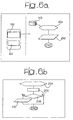
- Figure 6 illustrates an example of multilevel workflows mixed with rules engines that may cope with these circumstances.
- the level 1 process is again a workflow and requires that the alert message is displayed on a console of the MA when the ADSL connectivity 100 or the Mailbox sub-service 102 fails with additional information about fault reasons (see figure 6a , left).
- the level 2 process ( figure 6a , right) is rule-driven: the agent application KB (Knowledge Base) contains all relevant data (e.g. status of network resources, active alarms) collected from various events, from RPs but also from other AAs.
- the rule "Fault on ADSL path” is an example of alarm correlation (more precisely, fact correlation). For example, when the rule becomes true (step 200) it sends (in a step 202) a new event to the level 1 PE (inside the MA).
- the level 3 Process (shown in figure 6b in the case of check port fault, e.g. the equipment of Vendor A) is again rule-driven: a rule is executed (step 204) as soon as RP receives an event from PA, like a SNMP trap. This rule gets more information on port status (step 206) through PA interoperation. After checking in step 208 if port status is operative, it alerts the AA, if necessary, in step 210.
- Figure 7 shows the activity diagram for the various platform components.
- PA1 a SNMP protocol adapter
- PA1 receives a SNMP trap with information "Port X down" on a resource mirrored by RP1, along the ADSL path for "Offer 1" service.
- the rule engine on RP1 activates the rule “Check port fault”, then propagates the event to AA1.
- AA1 accept event and stores it in KB.
- a main advantage of the arrangement shown lies the reduction of network traffic due to alarm signaling. Every component (RP, AA and also MA) takes part in alarms processing on different abstraction levels. In that way the alarm correlation function can be implemented (e.g. at the level of the agents AAs) very close to the possible alarm sources. This approach reduces network traffic due to alarms having to be sent to a central system.
- the flexibility inherent in workflows and rules definition permits the introduction of new equipment with minimal effort (same advantage described in provisioning case).
- a third example highlights the flexibility of equipment management through level 3 workflow configuration.
- This example bears witness to the flexibility in data model handling: after the addition of a new equipment type in a network, by just redefining (e.g. by means of a GUI adapted to manage in a user-friendly manner XML files, for example) the mapping model, the proxy layer automatically creates and maintains a synchronized representation of the new equipment, while operation of all the FCAPS functionalities is the distributed layer is never discontinued.
- this example is intended to show how the arrangement disclosed can flexibly and easily handle a data model change for an equipment with its vendor and technology dependent features.
- the process of replacing a Vendor A equipment with a Vendor B equipment requires only updating the data model (if changed) and modifying of level 3 workflow processes.
- the RPs are able to recognize the new equipment and utilize the new data model and level 3 workflows to populate the data model.
- FIG 8 By way of example an ATM switch and the related scenario are shown in figure 8 .
- the common data model CMD (compliant with a common model like TMF's SID or DMTF's CIM) is specified using an XML schema file (xsd) stored in the MDB data base together with level 3 processes.
- the catalog data tables in the network inventory CNI hold the equipment catalog data (characteristic information needed to describe the network resources, often referred also as "metadata” or “templates”).
- the resource proxy RP represents the ATM Switch equipment of a vendor "A”. It holds the image EI of the ATM Switch equipment. Both the catalog data and the equipment image are validated using the common data model specified in the xsd file.
- This process includes a number of subtask that the operator O must carry out.
- a first subtask is to install the hardware equipment: this task deals with the physical installation of the new piece of equipment.
- a second subtask is to insert the new equipment in the catalog. Users have to insert the new equipment characteristic into the catalog (e.g. the new vendor name). It is assumed that the common catalog data are stored in a centralized network Inventory (CNI) OSS.
- CNI centralized network Inventory
- a third subtask is to rewrite the level 3 workflows. This is necessary in order to be able to manage the new equipment (using the new vendor dependent equipment commands) and to deal with the new equipment image (by means of the proper new commands to fill the Resource proxy memory image).
- FIG. 10 A portion of the level 3 workflows, involved in the resource proxy data model management, is shown in figures 10 .
- the workflow portions shown deal with the management of equipment card data.
- the workflow portion allows getting the various card attributes (named Attribute1, Attribute2, Attribute3) values from the equipment (step 308) and then to update (in a step 310) the resource proxy image with the values retrieved.
- Vendor B equipment card (Card B) contains only one attribute (named Attribute X). Therefore, the new workflow can be represented again with Figure 10 where step 308 and 310 contain commands to get only attribute X value from equipment and update the RP image consequently.
- the XML code below shows an XML version, compliant to the common data model, of the resource proxy image subsequent to the execution of the level 3 workflow for the vendor A equipment.
- the further XML code below shows an XML version, compliant to the common data model, of the resource proxy image subsequent to the execution of the level 3 Workflow for the vendor B equipment.
- FIG 11 shows the activity diagram of the various platform components involved in the resource proxy data model management.
- the GUI is intended to be the graphical user interface used by a human operator to work on the MDB and to control the MA.
- Eqpt stands for the equipment "ATM switch”.
- New equipment with their vendor dependent features is thus managed in a flexible and simple way.
- the process of replacing a Vendor A equipment with a vendor B equipment involves only the configuration of the network inventory catalog data and of the new level 3 workflow.
- the agents are able to recognize the new equipment in the catalog and the associated new level 3 workflow and to use these to manage the new equipment and its resource proxy image.
- the arrangement described can be extended for a number of layers greater than three, where the agent layer can be structured in a hierarchy.
- the proxy layer is not split in order to avoid introducing bottlenecks in the network interactions; also, evolution of equipment may result in the proxy layer being arranged in the equipments, when they will offer standard interfaces with a unified data model. If all functionalities can be implemented as distributed, a separate manager/coordinator layer can be dispensed with by promoting some agents to external communication tasks.
Landscapes
- Engineering & Computer Science (AREA)
- Computer Networks & Wireless Communication (AREA)
- Signal Processing (AREA)
- Computer And Data Communications (AREA)
- Management, Administration, Business Operations System, And Electronic Commerce (AREA)
- Data Exchanges In Wide-Area Networks (AREA)
Applications Claiming Priority (1)
| Application Number | Priority Date | Filing Date | Title |
|---|---|---|---|
| PCT/IT2003/000511 WO2005018249A1 (en) | 2003-08-19 | 2003-08-19 | System architecture method and computer program product for managing telecommunication networks |
Publications (2)
| Publication Number | Publication Date |
|---|---|
| EP1656800A1 EP1656800A1 (en) | 2006-05-17 |
| EP1656800B1 true EP1656800B1 (en) | 2009-07-15 |
Family
ID=34179283
Family Applications (1)
| Application Number | Title | Priority Date | Filing Date |
|---|---|---|---|
| EP03818101A Expired - Lifetime EP1656800B1 (en) | 2003-08-19 | 2003-08-19 | System architecture method and computer program product for managing telecommunication networks |
Country Status (10)
| Country | Link |
|---|---|
| US (1) | US8468228B2 (pt) |
| EP (1) | EP1656800B1 (pt) |
| CN (1) | CN1820514B (pt) |
| AU (1) | AU2003264870A1 (pt) |
| BR (2) | BR0318466A (pt) |
| CA (1) | CA2535440C (pt) |
| DE (1) | DE60328420D1 (pt) |
| ES (1) | ES2329570T3 (pt) |
| IL (1) | IL173543A (pt) |
| WO (1) | WO2005018249A1 (pt) |
Families Citing this family (22)
| Publication number | Priority date | Publication date | Assignee | Title |
|---|---|---|---|---|
| US7797459B1 (en) * | 2003-02-11 | 2010-09-14 | At&T Intellectual Property Ii, L.P. | Access independent common architecture for real-time communications services for networking environments |
| US8705518B1 (en) * | 2003-02-24 | 2014-04-22 | At&T Intellectual Property Ii, L.P. | Apparatus and method for controlling services and operations in converged communications networks |
| US20050091093A1 (en) * | 2003-10-24 | 2005-04-28 | Inernational Business Machines Corporation | End-to-end business process solution creation |
| US7346888B1 (en) * | 2004-03-01 | 2008-03-18 | Sprint Communications Company L.P. | Use case integration |
| EP1900144B1 (en) | 2005-07-06 | 2012-02-29 | Telecom Italia S.p.A. | Method and system for identifying faults in communication networks |
| CN101268656B (zh) | 2005-07-29 | 2010-12-08 | 意大利电信股份公司 | 用于生成指令信号以在通信网络中执行干预的方法和系统 |
| EP1932079A1 (en) | 2005-09-30 | 2008-06-18 | Telecom Italia S.p.A. | A method and system for automatically testing performance of applications run in a distributed processing structure and corresponding computer program product |
| US10027554B2 (en) * | 2005-11-18 | 2018-07-17 | Amdocs Systems Limited | Architecture for operational support system |
| US8141125B2 (en) * | 2005-11-30 | 2012-03-20 | Oracle International Corporation | Orchestration of policy engines and format technologies |
| US9558298B2 (en) | 2005-12-28 | 2017-01-31 | Telecom Italia S.P.A. | Method for the approximate matching of regular expressions, in particular for generating intervention workflows in a telecommunication network |
| KR101214195B1 (ko) | 2005-12-28 | 2012-12-24 | 텔레콤 이탈리아 소시에떼 퍼 아찌오니 | 특히, 전기통신 네트워크에서 중재를 위한 작업흐름 모델의 자동 생성 방법 |
| US8725674B1 (en) * | 2006-06-30 | 2014-05-13 | At&T Intellectual Property Ii, L.P. | Method and apparatus for providing a product metadata driven operations support system |
| US8051330B2 (en) | 2006-06-30 | 2011-11-01 | Telecom Italia S.P.A. | Fault location in telecommunications networks using bayesian networks |
| WO2008075122A1 (en) * | 2006-12-19 | 2008-06-26 | Telecom Italia S.P.A. | Method and system for providing teleassistance services based on software agents executing workflows |
| CN101557314A (zh) * | 2009-05-07 | 2009-10-14 | 中兴通讯股份有限公司 | 一种分布式网管系统及数据配置管理方法 |
| CN102402776A (zh) * | 2010-09-09 | 2012-04-04 | 姜怀臣 | 保险业视频网络培训互动平台 |
| CN102739450A (zh) * | 2012-06-29 | 2012-10-17 | 深圳市博瑞得科技有限公司 | 信令监测系统分布式平台架构及其处理方法 |
| WO2015101393A1 (en) | 2013-12-30 | 2015-07-09 | Telecom Italia S.P.A. | Augmented reality for supporting intervention of a network apparatus by a human operator |
| CN104811331B (zh) * | 2014-01-29 | 2018-07-03 | 华为技术有限公司 | 一种可视化网络运维方法和装置 |
| US9389901B2 (en) | 2014-09-09 | 2016-07-12 | Vmware, Inc. | Load balancing of cloned virtual machines |
| US9871702B2 (en) * | 2016-02-17 | 2018-01-16 | CENX, Inc. | Service information model for managing a telecommunications network |
| CN106502809B (zh) * | 2016-11-08 | 2019-10-08 | 上海基连网络科技有限公司 | 一种多平台应用程序适配方法、装置及终端设备 |
Family Cites Families (10)
| Publication number | Priority date | Publication date | Assignee | Title |
|---|---|---|---|---|
| US5522042A (en) * | 1994-01-28 | 1996-05-28 | Cabletron Systems, Inc. | Distributed chassis agent for distributed network management |
| IE77337B1 (en) * | 1995-08-15 | 1997-12-03 | Broadcom Eireann Research Limi | A communication network management system |
| JP3369445B2 (ja) * | 1997-09-22 | 2003-01-20 | 富士通株式会社 | ネットワークサービスサーバ負荷調整装置、方法および記録媒体 |
| WO2001002973A1 (en) | 1999-07-02 | 2001-01-11 | Covad Communications Group, Inc. | Process fulfillment systems and methods using distributed workflow management architecture |
| US7337209B1 (en) | 2000-04-28 | 2008-02-26 | Sheer Networks, Inc. | Large-scale network management using distributed autonomous agents |
| CA2368627A1 (en) * | 2000-04-28 | 2001-11-08 | Sharon Barkai | Network management method and system |
| US7225250B1 (en) * | 2000-10-30 | 2007-05-29 | Agilent Technologies, Inc. | Method and system for predictive enterprise resource management |
| US6968553B1 (en) * | 2001-03-01 | 2005-11-22 | Alcatel | Element manager common gateway architecture system and method |
| US20040001449A1 (en) * | 2002-06-28 | 2004-01-01 | Rostron Andy E. | System and method for supporting automatic protection switching between multiple node pairs using common agent architecture |
| US7209963B2 (en) * | 2002-07-11 | 2007-04-24 | International Business Machines Corporation | Apparatus and method for distributed monitoring of endpoints in a management region |
-
2003
- 2003-08-19 WO PCT/IT2003/000511 patent/WO2005018249A1/en not_active Ceased
- 2003-08-19 ES ES03818101T patent/ES2329570T3/es not_active Expired - Lifetime
- 2003-08-19 DE DE60328420T patent/DE60328420D1/de not_active Expired - Lifetime
- 2003-08-19 AU AU2003264870A patent/AU2003264870A1/en not_active Abandoned
- 2003-08-19 CN CN038269244A patent/CN1820514B/zh not_active Expired - Lifetime
- 2003-08-19 CA CA2535440A patent/CA2535440C/en not_active Expired - Lifetime
- 2003-08-19 BR BRPI0318466-8A patent/BR0318466A/pt active IP Right Grant
- 2003-08-19 US US10/568,688 patent/US8468228B2/en not_active Expired - Fee Related
- 2003-08-19 EP EP03818101A patent/EP1656800B1/en not_active Expired - Lifetime
- 2003-08-19 BR BRPI0318466-8A patent/BRPI0318466B1/pt unknown
-
2006
- 2006-02-05 IL IL173543A patent/IL173543A/en active IP Right Grant
Also Published As
| Publication number | Publication date |
|---|---|
| WO2005018249A1 (en) | 2005-02-24 |
| BRPI0318466B1 (pt) | 2017-06-20 |
| US8468228B2 (en) | 2013-06-18 |
| AU2003264870A1 (en) | 2005-03-07 |
| IL173543A (en) | 2011-02-28 |
| CA2535440A1 (en) | 2005-02-24 |
| CN1820514B (zh) | 2012-03-28 |
| US20060203732A1 (en) | 2006-09-14 |
| CN1820514A (zh) | 2006-08-16 |
| IL173543A0 (en) | 2006-07-05 |
| CA2535440C (en) | 2012-10-09 |
| BR0318466A (pt) | 2006-09-12 |
| DE60328420D1 (de) | 2009-08-27 |
| EP1656800A1 (en) | 2006-05-17 |
| ES2329570T3 (es) | 2009-11-27 |
Similar Documents
| Publication | Publication Date | Title |
|---|---|---|
| EP1656800B1 (en) | System architecture method and computer program product for managing telecommunication networks | |
| US8201180B2 (en) | System and method for defining associations between applications | |
| US7418513B2 (en) | Method and system for network management with platform-independent protocol interface for discovery and monitoring processes | |
| Szabo et al. | Elastic network functions: opportunities and challenges | |
| EP2815346B1 (en) | Coordination of processes in cloud computing environments | |
| EP1551129B1 (en) | Generic interface for subscription management | |
| US20020078213A1 (en) | Method and system for management of resource leases in an application framework system | |
| US20010027470A1 (en) | System, method and computer program product for providing a remote support service | |
| US10715457B2 (en) | Coordination of processes in cloud computing environments | |
| Somers | Hybrid: unifying centralised and distributed network management using intelligent agents | |
| Romanov et al. | Principles of building modular control plane in software-defined network | |
| WO2003034338A2 (en) | Management platform and environment | |
| Boutaba et al. | An architectural approach for integrated network and systems management | |
| Ecklund et al. | Dynamic end-to-end QoS management middleware for distributed multimedia systems | |
| van der Meer et al. | Ubiquitous Smart Space Management | |
| Liotta | Towards flexible and scalable distributed monitoring with mobile agents | |
| Pinard et al. | Issues In Using an Agent Framework For Converged Voice and Data Application. | |
| Deliverable | Overall Concepts and Principles of TINA | |
| Kutvonen | Management of Application Federations. | |
| de la Fuente et al. | Application of TINA-C architecture to management services | |
| van der Meer | Middleware and Management | |
| Kramp et al. | Descriptive-procedural configuration of communication bindings | |
| Popescu-Zeletin et al. | Y-Architecture for the integration of autonomous components | |
| Fokus et al. | MOBILE INTELLIGENT AGENTS IN ACTIVE VIRTUAL PIPES SUPPORT FOR VIRTUAL ENTERPRISES | |
| ARSENIS | In this paper, recently concluded work on the development of a communication support tool kit is reported. The analysis, design and implementation steps of this project follow closely the |
Legal Events
| Date | Code | Title | Description |
|---|---|---|---|
| PUAI | Public reference made under article 153(3) epc to a published international application that has entered the european phase |
Free format text: ORIGINAL CODE: 0009012 |
|
| 17P | Request for examination filed |
Effective date: 20060123 |
|
| AK | Designated contracting states |
Kind code of ref document: A1 Designated state(s): AT BE BG CH CY CZ DE DK EE ES FI FR GB GR HU IE IT LI LU MC NL PT RO SE SI SK TR |
|
| 17Q | First examination report despatched |
Effective date: 20060712 |
|
| DAX | Request for extension of the european patent (deleted) | ||
| 17Q | First examination report despatched |
Effective date: 20060712 |
|
| GRAP | Despatch of communication of intention to grant a patent |
Free format text: ORIGINAL CODE: EPIDOSNIGR1 |
|
| GRAS | Grant fee paid |
Free format text: ORIGINAL CODE: EPIDOSNIGR3 |
|
| GRAA | (expected) grant |
Free format text: ORIGINAL CODE: 0009210 |
|
| AK | Designated contracting states |
Kind code of ref document: B1 Designated state(s): AT BE BG CH CY CZ DE DK EE ES FI FR GB GR HU IE IT LI LU MC NL PT RO SE SI SK TR |
|
| REG | Reference to a national code |
Ref country code: CH Ref legal event code: EP Ref country code: GB Ref legal event code: FG4D |
|
| REG | Reference to a national code |
Ref country code: IE Ref legal event code: FG4D |
|
| REF | Corresponds to: |
Ref document number: 60328420 Country of ref document: DE Date of ref document: 20090827 Kind code of ref document: P |
|
| REG | Reference to a national code |
Ref country code: ES Ref legal event code: FG2A Ref document number: 2329570 Country of ref document: ES Kind code of ref document: T3 |
|
| NLV1 | Nl: lapsed or annulled due to failure to fulfill the requirements of art. 29p and 29m of the patents act | ||
| PG25 | Lapsed in a contracting state [announced via postgrant information from national office to epo] |
Ref country code: SE Free format text: LAPSE BECAUSE OF FAILURE TO SUBMIT A TRANSLATION OF THE DESCRIPTION OR TO PAY THE FEE WITHIN THE PRESCRIBED TIME-LIMIT Effective date: 20090715 Ref country code: FI Free format text: LAPSE BECAUSE OF FAILURE TO SUBMIT A TRANSLATION OF THE DESCRIPTION OR TO PAY THE FEE WITHIN THE PRESCRIBED TIME-LIMIT Effective date: 20090715 Ref country code: AT Free format text: LAPSE BECAUSE OF FAILURE TO SUBMIT A TRANSLATION OF THE DESCRIPTION OR TO PAY THE FEE WITHIN THE PRESCRIBED TIME-LIMIT Effective date: 20090715 |
|
| PG25 | Lapsed in a contracting state [announced via postgrant information from national office to epo] |
Ref country code: SI Free format text: LAPSE BECAUSE OF FAILURE TO SUBMIT A TRANSLATION OF THE DESCRIPTION OR TO PAY THE FEE WITHIN THE PRESCRIBED TIME-LIMIT Effective date: 20090715 Ref country code: NL Free format text: LAPSE BECAUSE OF FAILURE TO SUBMIT A TRANSLATION OF THE DESCRIPTION OR TO PAY THE FEE WITHIN THE PRESCRIBED TIME-LIMIT Effective date: 20090715 |
|
| PG25 | Lapsed in a contracting state [announced via postgrant information from national office to epo] |
Ref country code: MC Free format text: LAPSE BECAUSE OF NON-PAYMENT OF DUE FEES Effective date: 20090831 Ref country code: BG Free format text: LAPSE BECAUSE OF FAILURE TO SUBMIT A TRANSLATION OF THE DESCRIPTION OR TO PAY THE FEE WITHIN THE PRESCRIBED TIME-LIMIT Effective date: 20091015 Ref country code: PT Free format text: LAPSE BECAUSE OF FAILURE TO SUBMIT A TRANSLATION OF THE DESCRIPTION OR TO PAY THE FEE WITHIN THE PRESCRIBED TIME-LIMIT Effective date: 20091115 |
|
| REG | Reference to a national code |
Ref country code: CH Ref legal event code: PL |
|
| PG25 | Lapsed in a contracting state [announced via postgrant information from national office to epo] |
Ref country code: LI Free format text: LAPSE BECAUSE OF NON-PAYMENT OF DUE FEES Effective date: 20090831 Ref country code: DK Free format text: LAPSE BECAUSE OF FAILURE TO SUBMIT A TRANSLATION OF THE DESCRIPTION OR TO PAY THE FEE WITHIN THE PRESCRIBED TIME-LIMIT Effective date: 20090715 Ref country code: CH Free format text: LAPSE BECAUSE OF NON-PAYMENT OF DUE FEES Effective date: 20090831 Ref country code: CZ Free format text: LAPSE BECAUSE OF FAILURE TO SUBMIT A TRANSLATION OF THE DESCRIPTION OR TO PAY THE FEE WITHIN THE PRESCRIBED TIME-LIMIT Effective date: 20090715 Ref country code: RO Free format text: LAPSE BECAUSE OF FAILURE TO SUBMIT A TRANSLATION OF THE DESCRIPTION OR TO PAY THE FEE WITHIN THE PRESCRIBED TIME-LIMIT Effective date: 20090715 Ref country code: EE Free format text: LAPSE BECAUSE OF FAILURE TO SUBMIT A TRANSLATION OF THE DESCRIPTION OR TO PAY THE FEE WITHIN THE PRESCRIBED TIME-LIMIT Effective date: 20090715 |
|
| PLBE | No opposition filed within time limit |
Free format text: ORIGINAL CODE: 0009261 |
|
| STAA | Information on the status of an ep patent application or granted ep patent |
Free format text: STATUS: NO OPPOSITION FILED WITHIN TIME LIMIT |
|
| PG25 | Lapsed in a contracting state [announced via postgrant information from national office to epo] |
Ref country code: SK Free format text: LAPSE BECAUSE OF FAILURE TO SUBMIT A TRANSLATION OF THE DESCRIPTION OR TO PAY THE FEE WITHIN THE PRESCRIBED TIME-LIMIT Effective date: 20090715 Ref country code: BE Free format text: LAPSE BECAUSE OF FAILURE TO SUBMIT A TRANSLATION OF THE DESCRIPTION OR TO PAY THE FEE WITHIN THE PRESCRIBED TIME-LIMIT Effective date: 20090715 |
|
| 26N | No opposition filed |
Effective date: 20100416 |
|
| PG25 | Lapsed in a contracting state [announced via postgrant information from national office to epo] |
Ref country code: IE Free format text: LAPSE BECAUSE OF NON-PAYMENT OF DUE FEES Effective date: 20090819 |
|
| PG25 | Lapsed in a contracting state [announced via postgrant information from national office to epo] |
Ref country code: GR Free format text: LAPSE BECAUSE OF FAILURE TO SUBMIT A TRANSLATION OF THE DESCRIPTION OR TO PAY THE FEE WITHIN THE PRESCRIBED TIME-LIMIT Effective date: 20091016 |
|
| PG25 | Lapsed in a contracting state [announced via postgrant information from national office to epo] |
Ref country code: LU Free format text: LAPSE BECAUSE OF NON-PAYMENT OF DUE FEES Effective date: 20090819 |
|
| PG25 | Lapsed in a contracting state [announced via postgrant information from national office to epo] |
Ref country code: HU Free format text: LAPSE BECAUSE OF FAILURE TO SUBMIT A TRANSLATION OF THE DESCRIPTION OR TO PAY THE FEE WITHIN THE PRESCRIBED TIME-LIMIT Effective date: 20100116 |
|
| PG25 | Lapsed in a contracting state [announced via postgrant information from national office to epo] |
Ref country code: TR Free format text: LAPSE BECAUSE OF FAILURE TO SUBMIT A TRANSLATION OF THE DESCRIPTION OR TO PAY THE FEE WITHIN THE PRESCRIBED TIME-LIMIT Effective date: 20090715 |
|
| PG25 | Lapsed in a contracting state [announced via postgrant information from national office to epo] |
Ref country code: CY Free format text: LAPSE BECAUSE OF FAILURE TO SUBMIT A TRANSLATION OF THE DESCRIPTION OR TO PAY THE FEE WITHIN THE PRESCRIBED TIME-LIMIT Effective date: 20090715 |
|
| REG | Reference to a national code |
Ref country code: FR Ref legal event code: PLFP Year of fee payment: 14 |
|
| REG | Reference to a national code |
Ref country code: FR Ref legal event code: PLFP Year of fee payment: 15 |
|
| REG | Reference to a national code |
Ref country code: FR Ref legal event code: PLFP Year of fee payment: 16 |
|
| PGFP | Annual fee paid to national office [announced via postgrant information from national office to epo] |
Ref country code: IT Payment date: 20220819 Year of fee payment: 20 Ref country code: GB Payment date: 20220829 Year of fee payment: 20 Ref country code: ES Payment date: 20220901 Year of fee payment: 20 Ref country code: DE Payment date: 20220829 Year of fee payment: 20 |
|
| PGFP | Annual fee paid to national office [announced via postgrant information from national office to epo] |
Ref country code: FR Payment date: 20220825 Year of fee payment: 20 |
|
| P01 | Opt-out of the competence of the unified patent court (upc) registered |
Effective date: 20230528 |
|
| P02 | Opt-out of the competence of the unified patent court (upc) changed |
Effective date: 20230601 |
|
| REG | Reference to a national code |
Ref country code: DE Ref legal event code: R071 Ref document number: 60328420 Country of ref document: DE |
|
| REG | Reference to a national code |
Ref country code: ES Ref legal event code: FD2A Effective date: 20230825 |
|
| REG | Reference to a national code |
Ref country code: GB Ref legal event code: PE20 Expiry date: 20230818 |
|
| PG25 | Lapsed in a contracting state [announced via postgrant information from national office to epo] |
Ref country code: GB Free format text: LAPSE BECAUSE OF EXPIRATION OF PROTECTION Effective date: 20230818 Ref country code: ES Free format text: LAPSE BECAUSE OF EXPIRATION OF PROTECTION Effective date: 20230820 |