EP1656869A2 - Distributeur pour papier enroulé - Google Patents
Distributeur pour papier enroulé Download PDFInfo
- Publication number
- EP1656869A2 EP1656869A2 EP05024560A EP05024560A EP1656869A2 EP 1656869 A2 EP1656869 A2 EP 1656869A2 EP 05024560 A EP05024560 A EP 05024560A EP 05024560 A EP05024560 A EP 05024560A EP 1656869 A2 EP1656869 A2 EP 1656869A2
- Authority
- EP
- European Patent Office
- Prior art keywords
- turret
- tissue
- dispenser
- dispensing
- spindles
- Prior art date
- Legal status (The legal status is an assumption and is not a legal conclusion. Google has not performed a legal analysis and makes no representation as to the accuracy of the status listed.)
- Withdrawn
Links
Images






Classifications
-
- A—HUMAN NECESSITIES
- A47—FURNITURE; DOMESTIC ARTICLES OR APPLIANCES; COFFEE MILLS; SPICE MILLS; SUCTION CLEANERS IN GENERAL
- A47K—SANITARY EQUIPMENT; ACCESSORIES THEREFOR, e.g. TOILET ACCESSORIES
- A47K10/00—Body-drying implements; Toilet paper; Holders therefor
- A47K10/24—Towel dispensers; Toilet paper dispensers
- A47K10/32—Dispensers for paper towels or toilet paper
- A47K10/34—Dispensers for paper towels or toilet paper dispensing from a web, e.g. with mechanical dispensing means
- A47K10/38—Dispensers for paper towels or toilet paper dispensing from a web, e.g. with mechanical dispensing means the web being rolled-up
-
- A—HUMAN NECESSITIES
- A47—FURNITURE; DOMESTIC ARTICLES OR APPLIANCES; COFFEE MILLS; SPICE MILLS; SUCTION CLEANERS IN GENERAL
- A47K—SANITARY EQUIPMENT; ACCESSORIES THEREFOR, e.g. TOILET ACCESSORIES
- A47K10/00—Body-drying implements; Toilet paper; Holders therefor
- A47K10/24—Towel dispensers; Toilet paper dispensers
- A47K10/32—Dispensers for paper towels or toilet paper
- A47K2010/3206—Coreless paper rolls
-
- A—HUMAN NECESSITIES
- A47—FURNITURE; DOMESTIC ARTICLES OR APPLIANCES; COFFEE MILLS; SPICE MILLS; SUCTION CLEANERS IN GENERAL
- A47K—SANITARY EQUIPMENT; ACCESSORIES THEREFOR, e.g. TOILET ACCESSORIES
- A47K10/00—Body-drying implements; Toilet paper; Holders therefor
- A47K10/24—Towel dispensers; Toilet paper dispensers
- A47K10/32—Dispensers for paper towels or toilet paper
- A47K2010/3253—Dispensers for paper towels or toilet paper with one or more reserve rolls
Definitions
- the present invention relates generally to dispensers for rolls of tissue.
- a preferred embodiment is a four-roll, gravity-feed roll dispenser for tissue rolls.
- Dispensers for tissue rolls are well known in the art. There is shown, for example, in United States Patent No. 6,752,349 to Moody et al. a tissue dispenser for two rolls of coreless tissue.
- the dispenser includes a support sled for mounting the rolls.
- the support sled is provided with latch dog assemblies which are biased towards a release position such that a second roll will become available when a first coreless tissue roll is depleted.
- the dispenser of the '349 patent accommodates two rolls; in many cases more capacity is desired.
- dispensers have been proposed for three or more rolls.
- the dispenser includes a support having a housing with an opening.
- a roll holder is rotatably mounted on the support and has three spaced roll support shafts or spindles which are inserted into rolls.
- the roll holder and rolls are maintained in an unbalanced condition to sequentially present the rolls at a dispensing position under the influence of gravity.
- High capacity dispensers are especially desirable for commercial establishments.
- Three roll dispensers inherently require incomplete loading for reliable operation by way of gravity.
- One existing solution is the use of very high capacity, large diameter (up to 1 ft or so in diameter) single rolls; however these rolls are difficult to handle and load into the dispenser.
- large roll dispensers are either without reserve rolls or are difficult to operate and re-load; a condition leading to the unavailability of tissue when needed.
- a gravity-feed tissue roll dispenser for a plurality of tissue rolls includes: (a) a housing; (b) a supply turret with a plurality of spindles for mounting a plurality of tissue rolls for dispensing; (c) means for rotatably mounting the supply turret in the housing about a center of rotation such that a vertical line through the center of rotation of the turret defines a biasing sector of the dispenser and the spindles rotate between upper and lower positions, the dispenser also having a dispensing sector adjacent the biasing sector; (d) stop means adapted for securing a loaded spindle in an elevated dispensing position in the dispensing sector of the tissue dispenser, the dispensing position being elevated with respect to a lower limit of travel of the spindle upon rotation of the turret; wherein the
- the stop means include a plurality of release arms which are mounted on the turret and biased toward a release position, the release arms being further adapted to be compressed to a locking position when the spindle is loaded with a coreless or other suitable tissue roll.
- the release arms are pivotally mounted and adapted to engage the end of a tissue roll loaded onto an associated spindle whereby the arms are compressed to their locking positions; to this end the release arms have terminal portions gapped with an associated spindle a predetermined distance such that the release arm will assume its release position upon depletion of a tissue roll loaded onto its associated spindle.
- the terminal portions of the release arms are generally arcuate such that a gap between a release arm and its associated spindle is of generally uniform width in the locking position of the release arm.
- the release arms have latch projections mounted thereon configured to cooperate with a locking shoulder on a back plate upon which the supply turret is mounted in order to secure the turret in the dispensing position.
- the dispenser further comprises means for manually advancing the turret in a dispensing direction, such as wherein the turret has gear teeth about its periphery and the means for manually advancing the turret include a geared advancing wheel which engages the gear teeth of the turret.
- the advancing wheel is mounted on a one-way bearing and has a molded-in direction indicator.
- the dispenser typically includes means for preventing rotation of the turret in a direction opposite the dispensing direction.
- the housing of the dispenser includes a back plate, a cover hinged thereto and optionally locking means for securing the cover to the back plate in a locking position.
- the locking means may include a latch member mounted in a cavity in the back plate and the latch member may be an injection-molded part which includes integrally formed biasing projections bearing upon surfaces of the cavity to urge the latch member to a locking position.
- a line from the spindle secured in the dispensing position to an opposed spindle in the biasing sector of the dispenser typically makes an angle, ⁇ , of from about 10° to about 30° with a vertical passing through the center of rotation of the turret.
- the means for rotatably mounting the supply turret in the housing comprises a mandrel with a stepped profile and the supply turret comprises a mounting wheel and a retaining plate each of which have molded-in features for securing them to each other.
- the mounting wheel and retaining plate may be rotationally lockable to each other along a relative locking direction co-directional with a dispensing direction in which the turret rotates to supply additional product.
- the mounting plate has a plurality of release arms provided with biasing means and the retaining plate is adapted to secure the biasing means of the release arms to the mounting plate of the turret, thereby eliminating the need for additional hardware.
- a preferred construction is a gravity-feed tissue roll dispenser for tissue rolls comprising: (a) a housing; (b) a supply turret with four equally spaced of spindles for mounting tissue rolls for dispensing; (c) a back plate for rotatably mounting the supply turret in the housing about a center of rotation such that a vertical line through the center of rotation of the turret divides the dispenser into a biasing sector and a dispensing sector, the spindles being mounted to rotate between upper and lower positions ; and (d) stop means adapted for securing a loaded spindle in an elevated dispensing position in the dispensing sector of the tissue dispenser, the dispensing position being elevated with respect to a lower limit of travel of the spindle upon rotation of the turret; wherein the stop means are responsive to depletion of the loaded spindle so as to allow rotation of the turret upon depletion of a roll of tissue mounted thereabout; the dispensing position of a loaded spindle being further
- a gravity-feed tissue roll dispenser for a plurality of tissue rolls comprising: (a) a housing with a dispensing opening for allowing access to tissue contained in the dispenser; (b) a supply turret with a plurality of spindles for mounting a plurality of tissue rolls for dispensing; (c) means for rotatably mounting the supply turret in the housing; (d) stop means adapted for securing a loaded spindle in a dispensing position, the stop means being responsive to depletion of the loaded spindle so as to allow rotation of the turret upon depletion of a roll of tissue mounted thereabout; and (e) a plurality of sequestering members mounted on the turret and associated with the spindles, each sequestering member being adapted to cooperate with the housing in order to hinder access to a tissue roll on its associated spindle until the spindle is in the dispensing position.
- the means for rotatably mounting the supply turret in the housing are configured to mount the turret about a center of rotation such that a vertical line through the center of rotation of the turret defines a biasing sector of the dispenser and the spindles rotate between upper and lower positions, the dispenser also having a dispensing sector adjacent the biasing sector, and wherein the dispensing position is elevated with respect to a lower limit of travel of the spindle upon rotation of the turret.
- the turret and stop means are configured such that when a loaded spindle is secured in the elevated dispensing position: (i) at least two spindles are in the biasing sector of the dispenser and (ii) the number of spindles in the biasing sector is equal to or greater than the number of other spindles in the dispensing sector, such that when the dispenser is fully loaded with a plurality of like tissue rolls, depletion of a roll in the elevated dispensing position distributes the weight of tissue in the dispenser so as to bias the turret in a dispensing direction.
- the sequestering members have plates are curved plates and may be discrete components or the sequestering plates are injection-molded as part of a unitary structure.
- Another aspect of the invention involves (a) dispensing a plurality of tissue rolls in a dispenser of the invention and (b) withdrawing the tissue from the dispenser.
- a preferred embodiment is a dispenser for four rolls of tissue arranged at equally spaced intervals on a circular turret.
- This offset from vertical places more weight on the right side (biasing sector) of the dispenser as viewed from the front which provides for gravity to automatically advance the rolls in a clockwise manner when the roll in use is consumed. That is to say, when a roll is fully consumed a release arm raises from its compressed position to travel over a stop shoulder on the back plate.
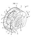
- Dispenser 10 including a housing 12 with a cover 14.
- Dispenser 10 has a back plate 16 with a mandrel 18 for mounting a turret 20.
- Turret 20 has a cylindrical support 19 for mounting the turret on mandrel 18 of back plate 16 as well as four spindles, spindle 22, spindle 24, spindle 26, and spindle 28. Each spindle has a release arm such as release arms 30, 32, 34, and 36 associated therewith. Operation of the release arms will be further appreciated from the discussion below.
- Other features of the dispenser generally include an advancing wheel 38 for manually advancing turret 20 along a dispensing direction 40. To this end, advancing wheel 38 has gear teeth 42 which engage another set of gear teeth 44 on turret 20. Advancing wheel 38 is mounted on a one way bearing indicated at 46 which prevents the turret from rotating opposite dispensing direction 40.
- advancing wheel 38 is rotated in direction 48 i.e., a counter-clockwise direction in order to advance turret 20 in the dispensing direction. Otherwise, the one-way bearing indicatect at 46 will prevent unwanted rotation of supply turret 20 as noted above by way of inter-engagement of the gear teeth.
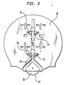
- Latching member 50 having two arcuate spring portions 52 and 54.
- Latching member 50 is adapted to be mounted in a cavity of back plate 16 as shown having a plurality of surfaces adapted to engage springs 52 and 54 so that the latching member is urged to a locking position by action of springs 52, 54 on surfaces such as surfaces 58 and 60.
- Latching member 50 is preferably of unitary construction; such as being injection molded and may be made from an engineering resin such as polyacetal, nylon, polyester or the like.
- the release arms are pivotably mounted in turret 20 by way of a hinge 62 ( Figure 5) and each include a spring 64 to bias the release arms to an unlocked position such as is shown on the lower portion of Figure 10 at 66.
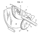
- the release arms generally have the features shown in Figures 4, 5, 7 and 8. It can be seen from the various figures that each release arm has an arcuate terminal portion 68 as well as a latch projection 70 adapted to cooperate with a locking shoulder 72 of back plate 16 ( Figure 6).
- the release arms have an arcuate end 68 as noted above such that it is gapped with its associated spindle as is seen in Figures 4 and 5.
- the dispenser when fully loaded, is adapted to hold four rolls on spindles 22, 24, 26 and 28, for example, roll 74, roll 76, roll 78, and roll 80 as is shown in the various Figures.
- a roll When a roll is in the dispensing position, indicated at 90 in Figures 1 and 9, two of the rolls of a fully loaded dispenser rolls 78 and 80 are mounted on spindles in a biasing sector 92 of the dispenser while rolls 74 and 76 are mounted in a dispensing sector 94 of the dispenser.
- the various sectors are defined by a vertical line 96 passing through the centre of mandrel 18 that is to say, passing through the center of rotation of turret 20.
- the sector of the dispenser to the right of line 96 maybe thought of as the biasing sector and the area to the left of line 96 may be thought of as the dispensing sector of the dispenser. See Figure 9.
- a line 97 between spindles 22 and 26 defines an angle ⁇ with line 96 where ⁇ may be anywhere from about 10 to about 30° in preferred embodiments.
- release arm 30 springs from its locking position, i.e., compressed position, as in Figure 1 and as shown at 98 in the upper part of Figure 10 to a release or unlocked position shown at 66 in Figure 10.
- latch projection 70 no longer engages locking shoulder 72 of back plate 16 when the release arm is in its unlocked or release position.
- the turret 20 is now free to rotate in dispensing direction 40 under the influence of gravity due to the weight distribution of tissue in the dispenser.
- turret 20 advances automatically under the influence of gravity until roll 80 is locked into position by virtue of its release arm interacting with locking shoulder 72.
- dispensing position 90 is elevated with respect to the lower limit of travel of spindle 22, i.e., that is, when spindle 22 is coincident with vertical line 96.
- the biasing force that is the weight of tissue in the biasing sector has a magnified effect on inducing rotation of turret 20 in the desired direction.
- a salient feature of the invention is a plurality of rolls mounted in the biasing sector for distributing the weight of tissue for automatic advancement along the dispensing direction.
- FIG. 11-19 there is shown another dispenser 110 including a housing 112 with a cover 114.
- Dispenser 110 has a back plate 116 with a mandrel 118 for mounting a turret 120.
- Turret 120 has a cylindrical support 119 for mounting the turret on mandrel 118 of back plate 116 as well as four sleeved spindles, spindle 122, spindle 124, spindle 126, and spindle 128.
- Each sleeved spindle has a release arm such as release arms 130, 132, 134, and 136 associated therewith. Operation of the release arms will be appreciated from the discussion above with respect to corresponding parts of dispenser 10.
- advancing wheel 138 for manually advancing turret 120 along a dispensing direction 140.
- advancing wheel 138 has gear teeth 142 which engage another set of gear teeth 144 on turret 120.
- Advancing wheel 138 is mounted on a one way bearing indicated at 146 which prevents the turret from rotating opposite dispensing direction 140.
- advancing wheel 138 is rotated in direction 148 i.e., a counter-clockwise direction in order to advance turret 120 in the dispensing direction. Otherwise, the one-way bearing indicated at 146 will prevent unwanted rotation of supply turret 120 as noted above by way of inter-engagement of the gear teeth.
- Latching member 150 having two arcuate spring portions 152 and 154.
- Latching member 50 is adapted to be mounted in a cavity of back plate 116 as shown having a plurality of surfaces adapted to engage springs 152 and 154 so that the latching member is urged to a locking position by action of springs 152, 154 on surfaces such as surfaces 158 and 160.
- Latching member 150 is preferably of unitary construction; such as being injection molded and may be made from an engineering resin such as polyacetal, nylon, polyester or the like.
- the release arms are pivotably mounted in turret 120 by way of a hinge and each include a spring to bias the release arms to an unlocked position such as is shown on the lower portion of Figure 10 at 66.
- the release arms generally have the features shown and described above in connection with
- Dispenser 110 operates generally as described above in connection with dispenser 10 of Figures 1-10.
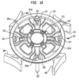
- Various improvements include a plurality of sequestering members 180, 182, 184, 186 associated respectively with spindles 122, 124, 126, 128.
- the members include curved plates and are configured and disposed on turret 120 to cooperate with housing 112 in order to hinder access to rolls of tissue disposed on the spindles until the spindles are in a dispensing position indicated at 190. That is to say, the members 180-186 block access through opening 195 in housing 112 to tissue rolls when they are not in dispensing position 190, such as when they are in biasing sector 192.
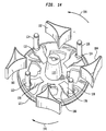
- the sequestering plates have curved plates and may be discrete components as shown in Figures 12, 13 and 15.
- the plates may be put on an injection-molded unitary structure as is shown in Figure 20.
- Plate 116 includes a cavity 117 provided with shoulders 119a, 119b, 123, 125 to limit travel of latching member 150 such that it does not interfere with wheel 138, especially in the home position when the latch member is urged outwardly by springs 152, 154.
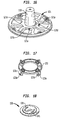
- Plate 116 also preferably includes a plurality of curved ribs such as ribs 131, 133 ( Figure 19) for spring release arms 130, 132 and from plate 116 so that they will not bend against plate.
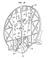
- mandrel 118 also includes a stepped profile with segments 118a, 18b, 118c, 118d to reduce friction or binding between mandrel 118 and cylindrical support 119.
- FIG. 11 A still further feature is shown in Figures 11, 12 and 18 wherein the face of wheel 138 is provided with a pair of directional arrows 139, 141 to show the direction of rotation of the wheel to manually advance turret 120 when necessary in order to dispense more product.
- the arrows project upwardly away from the adjacent surface 0.010 inches or so.
- the inventive dispenser is made from injection-molded parts which reduce the need for additional hardware and reduce or avoid the need for molding or drilling holes, especially in areas which might have relatively high molded-in stress such as at the base of cylindrical support 119.
- turret 120 includes a mounting wheel 121 with a plurality of molded-in directional shelves such as shelves 121a, 121b and 121c which project along dispensing direction 140.
- the shelves are provided with cavities such as cavities 121d, 121e.
- a retaining plate 123 includes a plurality of L-shaped, molded-in brackets 123a, 123b and so forth provided with projections 123c, 123d and so forth.
- the brackets, shelves, projections and cavities cooperate to secure retaining plate 123 to mounting plate 120 in order to secure springs 164a, 164b, 164c, 164d of release arms 130, 132, 134 and 136 to the turret.
- wheel 121 and plate 123 are thus lockable to each other by relative rotation in dispensing direction 140.
- their relative motion In order to unlock the plates, their relative motion must be opposite the direction of rotation in normal operation such that in normal use, separation does not occur. That is to say, mounting plate 121 needs to be rotated counterclockwise (191, Figure 14; 148, Figure 11) with respect to plate 123 in order to separate them.
- Figure 20 shows a unitary member 281 defining sequestering plates 280, 282, 284 and 286 having generally the configuration and blocking functions of plates 180-186 of Figures 12, 14 and 15.
- Member 281 is mounted on a turret 220 which is then placed in a dispenser such as dispenser 10 or 110 as described above.
- Figure 21 shows a preferred construction of a turret 320 for use in connection with the inventive dispenser.
- Turret 320 has a cylindrical support 319 for mounting the turret on the mandrel of the back plate. There is also provided four sleeved spindles, spindle 322, spindle 324, spindle 326, and spindle 328. Each sleeve spindle has a release arm such as release arms 330, 332, 334, and 336 associated therewith. Operation of the release arms is appreciated from the discussion above with respect to the corresponding parts of dispenser 10 and the corresponding parts of dispenser 110.
- Turret 320 includes a plurality of sequestering members 380, 382, 384, and 386 associated respectively with spindles 322, 324, 326 and 328.
- Each of the sequestering members includes first and second panels as is shown in Figure 21. That is to say, sequestering member 380 has curved panels 380a and 380b, while sequestering member 382 has panels 382a and 382b.
- Sequestering member 384 has panel 384a and 384b while panel 386 has panel 386a and 386b.
- the curved panels are joined where the sequestering members are mounted on turret 320 and flare outwardly from that point away from each other as shown in Figure 21.
- sequestering members are thus configured and disposed in order to hinder access to the rolls of tissue disposed on the spindles until the spindles are in the dispensing position. That is to say, sequestering members 380, 382, 384, and 386 are adapted to hinder access to a roll not in the dispensing position as tissue is dispensed from the inventive dispenser.
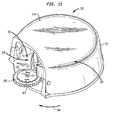
- FIG 22 shows yet another embodiment 410 of the inventive dispenser, wherein the housing is at least partially transparent so that tissue inventory may be observed.
- Dispenser 410 includes a turret 420 as noted above in connection with other embodiments wherein the turret has four spindles 422, 424, 426 and 428. Mounted on the turret is a plurality of tissue rolls 474, 476, 478, and 480. Note that roll 474 is in the dispensing position.
- dispenser 410 has an outer housing front cover 414 made of plastic.
- cover 414 is integrally formed by way of injection molding of a thermoplastic resin composition including an acrylic resin (poly(methyl methacrylate) for example) or polycarbonate resin, or the like such that cover 414 has a unitary structure.
- Cover 414 has a front 442 provided with polished areas 444 and textured areas 446.
- cover 414 is made from a transparent or lightly pigmented resin composition such that polished or smooth areas 444 are relatively transparent and textured areas 446 are translucent or relatively opaque depending on desired effect.
- the polished areas define an arcuate region 450 extending substantially around the entire periphery of turret 420.
- the polished transparent area is adapted to allow viewing of the tissue area at each of spindles 422, 424, 426 and 428. This may be accomplished by having an arcuate structure extending over about 300 degrees or more of a circular turret, for example as is shown in Figure 22.
- Smooth or polished areas can be provided by polishing the mold, while textured areas can be produced by texturing the surface of the mold by way of sandblasting, vapor honing or any other suitable technique.
- the smooth (polished), relatively transparent areas 444 of cover 414 are shown in oblique lines, while the textured areas 446 are stippled.
- a logo area 452 conveniently achieved by way of molding in the logo with a textured suface while molding the rest of the logo area with a polished mold surface.
- an embossment depth or molded in depth of about half that of the cover i.e. for a 120 mil thick cover
- a suitable molded in depth for the logo is about 60 mils, that is to say the cover is about half thickness in the textured area of the logo.
- relatively transparent area of the front cover includes a plurality of discrete relatively transparent areas.
- the relatively transparent area of the front cover is adapted and positioned to facilitate simultaneous viewing of roll inventory on all of the spindles of the dispenser disposed in a position other than the dispensing position. It is not necessary to view the inventory of the spindle in the dispensing position through the front cover since the spindle is exposed in any event; however in a preferred construction the spindle inventory of the spindle in the dispensing position is also simultaneously viewable with the inventory of the other spindles.
- a relatively transparent area of the front cover is ring-shaped, wherein the ring-shaped area is sized and positioned to facilitate simultaneous viewing of roll inventory on at least two spindles of the dispenser.
Landscapes
- Health & Medical Sciences (AREA)
- Public Health (AREA)
- Details Of Rigid Or Semi-Rigid Containers (AREA)
- Branching, Merging, And Special Transfer Between Conveyors (AREA)
- Replacement Of Web Rolls (AREA)
Applications Claiming Priority (3)
| Application Number | Priority Date | Filing Date | Title |
|---|---|---|---|
| US62707104P | 2004-11-12 | 2004-11-12 | |
| US69027305P | 2005-06-14 | 2005-06-14 | |
| US11/270,005 US7461810B2 (en) | 2004-11-12 | 2005-11-09 | Tissue roll dispenser |
Publications (2)
| Publication Number | Publication Date |
|---|---|
| EP1656869A2 true EP1656869A2 (fr) | 2006-05-17 |
| EP1656869A3 EP1656869A3 (fr) | 2009-10-21 |
Family
ID=40086474
Family Applications (1)
| Application Number | Title | Priority Date | Filing Date |
|---|---|---|---|
| EP05024560A Withdrawn EP1656869A3 (fr) | 2004-11-12 | 2005-11-10 | Distributeur pour papier enroulé |
Country Status (2)
| Country | Link |
|---|---|
| US (2) | US7461810B2 (fr) |
| EP (1) | EP1656869A3 (fr) |
Cited By (2)
| Publication number | Priority date | Publication date | Assignee | Title |
|---|---|---|---|---|
| CN107773138A (zh) * | 2017-11-08 | 2018-03-09 | 魏凡 | 一种生活用纸存取装置 |
| EP3695765A3 (fr) * | 2019-02-13 | 2020-11-11 | San Jamar, Inc. | Distributeur de type carrousel |
Families Citing this family (27)
| Publication number | Priority date | Publication date | Assignee | Title |
|---|---|---|---|---|
| KR100954857B1 (ko) * | 2007-08-28 | 2010-04-28 | 오태용 | 멀티 롤 화장지 장착용 보관 용기 |
| US8356767B2 (en) * | 2009-12-15 | 2013-01-22 | Sca Tissue North America Llc | Dispenser for multiple rolls of web material with automatic roll transfer, and method of loading same |
| USD818737S1 (en) | 2015-12-10 | 2018-05-29 | Gpcp Ip Holdings Llc | Dispenser |
| DE202016102766U1 (de) | 2016-04-26 | 2016-06-30 | Kawa Abdul Sharif | Toilettenpapier-Spender |
| CN106821110B (zh) * | 2016-12-28 | 2019-03-15 | 重庆一锄商贸有限公司 | 卷筒纸抽纸装置 |
| US10952569B2 (en) | 2017-05-10 | 2021-03-23 | Gpcp Ip Holdings Llc | Premature replacement prevention or deterrence for multiple roll sheet product dispensers |
| USD850145S1 (en) | 2017-05-15 | 2019-06-04 | Gpcp Ip Holdings Llc | Sheet product dispenser |
| USD878078S1 (en) * | 2017-07-13 | 2020-03-17 | Kimberly-Clark Worldwide, Inc. | Paper product dispenser |
| CN107713882A (zh) * | 2017-11-07 | 2018-02-23 | 昆明理工大学 | 一种风扇形厕纸盒装置及其使用方法 |
| CA179934S (en) | 2018-02-23 | 2020-03-05 | Cascades Canada Ulc | Dispenser |
| CA179935S (en) | 2018-02-23 | 2020-03-05 | Cascades Canada Ulc | Dispenser |
| CA3035709C (fr) | 2018-03-09 | 2025-09-23 | Cascades Canada Ulc | Distributeur de materiau en bande et methode |
| CN108553011A (zh) * | 2018-04-23 | 2018-09-21 | 佛山市旅行青蛙科技有限公司 | 一种智能出纸系统 |
| CA181664S (en) | 2018-05-29 | 2021-03-08 | Cascades Canada Ulc | Paper dispenser |
| CA181663S (en) | 2018-05-29 | 2021-03-08 | Cascades Canada Ulc | Paper dispenser |
| CA181854S (en) | 2018-06-07 | 2020-03-05 | Cascades Canada Ulc | Paper dispenser |
| US11825993B2 (en) | 2018-07-09 | 2023-11-28 | Gpcp Ip Holdings Llc | Spindle and cover components for sheet product dispensers and dispenser systems including such components |
| US11072513B2 (en) | 2019-03-28 | 2021-07-27 | San Jamar, Inc. | Rolled web material dispenser material lockout systems |
| USD1009613S1 (en) | 2019-03-28 | 2024-01-02 | San Jamar, Inc | Roll towel dispenser lockout |
| US11224316B2 (en) | 2019-03-28 | 2022-01-18 | San Jamar, Inc. | Rolled web material dispenser material lockout systems |
| US11071417B2 (en) | 2019-03-28 | 2021-07-27 | San Jamar, Inc. | Rolled web material dispenser material lockout systems |
| USD899806S1 (en) | 2019-03-28 | 2020-10-27 | San Jamar, Inc. | Roll towel dispenser lockout |
| US11083348B2 (en) | 2019-03-28 | 2021-08-10 | San Jamar, Inc. | Rolled web material dispenser material lockout systems |
| US12507839B2 (en) | 2019-11-22 | 2025-12-30 | Gpcp Ip Holdings Llc | Frictional features for rolled sheet product dispensers |
| USD1027485S1 (en) | 2020-03-24 | 2024-05-21 | San Jamar, Inc. | Rolled material dispenser lockout |
| US11447355B2 (en) | 2020-06-03 | 2022-09-20 | San Jamar, Inc. | Rolled web material feed assembly |
| AU2024200967A1 (en) * | 2023-02-20 | 2024-09-05 | Hysential Pty Ltd | A Carousel Tissue Dispenser |
Citations (9)
| Publication number | Priority date | Publication date | Assignee | Title |
|---|---|---|---|---|
| US2930664A (en) | 1957-03-18 | 1960-03-29 | American Linen Supply Company | Towel dispensing apparatus and method |
| US4108513A (en) | 1976-12-17 | 1978-08-22 | Cepasy Ag | Paper dispenser, especially toilet paper dispenser |
| US4557426A (en) | 1984-06-28 | 1985-12-10 | Siciliano Stephen J | Dispenser for toilet paper and the like |
| US4989800A (en) | 1989-10-03 | 1991-02-05 | Tritch Kim M | Tissue roll dispenser |
| GB2245882A (en) | 1990-06-12 | 1992-01-15 | Crisp & Wilson Ltd | Dispenser for disposable sheet supplied in roll form |
| US5310129A (en) | 1993-05-17 | 1994-05-10 | James River Paper Company, Inc. | System for sequentially dispensing web material from a plurality of rolls |
| US5636182A (en) | 1995-01-18 | 1997-06-03 | Fuji Ultrasonic Engineering Co., Ltd. | Portable ultrasonic underwater sensor |
| US6648267B2 (en) | 2000-03-09 | 2003-11-18 | Bay West Paper Corporation | Double core tissue roll, dispenser and method |
| US6752349B2 (en) | 2001-12-20 | 2004-06-22 | Fort James Corporation | Support sled for rolls of absorbent sheet and dispenser incorporating same |
Family Cites Families (15)
| Publication number | Priority date | Publication date | Assignee | Title |
|---|---|---|---|---|
| US543745A (en) * | 1895-07-30 | John j | ||
| US556482A (en) * | 1896-03-17 | Baling-press | ||
| US543402A (en) * | 1895-07-23 | Valborg emmilie poppen-s | ||
| US1456790A (en) * | 1920-09-18 | 1923-05-29 | Albert C Grunwald | Toilet-paper cabinet |
| US1462333A (en) * | 1921-08-26 | 1923-07-17 | Girard John | Roll fabric holder |
| US4651910A (en) * | 1986-01-17 | 1987-03-24 | Bud Antle, Inc. | Tape dispenser |
| US4872601A (en) * | 1987-09-04 | 1989-10-10 | Scott Paper Company | Two large roll toilet tissue dispenser |
| US5265816A (en) * | 1992-08-07 | 1993-11-30 | Fort Howard Corporation | Double roll tissue dispenser with sliding door |
| CA2171491C (fr) | 1995-03-10 | 2005-09-27 | John Michael Conner | Appareil distributeur |
| US6364245B1 (en) * | 2000-03-28 | 2002-04-02 | Alwin Manufacturing Co., Inc. | Toilet roll dispenser for different diameter core rolls |
| US6616087B1 (en) * | 2002-07-26 | 2003-09-09 | Shyue Jinn Chern | Rotary tape dispenser |
| US7014140B2 (en) * | 2004-01-30 | 2006-03-21 | Bay West Paper Corporation | Three roll tissue dispenser |
| USD543745S1 (en) * | 2005-11-09 | 2007-06-05 | Georgia-Pacific Consumer Products Lp | Tissue roll dispenser |
| USD556482S1 (en) * | 2005-11-09 | 2007-12-04 | Georgia-Pacific Consumer Products Lp | Tissue roll dispenser cover |
| USD543402S1 (en) * | 2005-11-09 | 2007-05-29 | Georgia-Pacific Consumer Products Lp | Tissue roll dispenser |
-
2005
- 2005-11-09 US US11/270,005 patent/US7461810B2/en active Active
- 2005-11-10 EP EP05024560A patent/EP1656869A3/fr not_active Withdrawn
-
2008
- 2008-11-07 US US12/266,629 patent/US20090065627A1/en not_active Abandoned
Patent Citations (9)
| Publication number | Priority date | Publication date | Assignee | Title |
|---|---|---|---|---|
| US2930664A (en) | 1957-03-18 | 1960-03-29 | American Linen Supply Company | Towel dispensing apparatus and method |
| US4108513A (en) | 1976-12-17 | 1978-08-22 | Cepasy Ag | Paper dispenser, especially toilet paper dispenser |
| US4557426A (en) | 1984-06-28 | 1985-12-10 | Siciliano Stephen J | Dispenser for toilet paper and the like |
| US4989800A (en) | 1989-10-03 | 1991-02-05 | Tritch Kim M | Tissue roll dispenser |
| GB2245882A (en) | 1990-06-12 | 1992-01-15 | Crisp & Wilson Ltd | Dispenser for disposable sheet supplied in roll form |
| US5310129A (en) | 1993-05-17 | 1994-05-10 | James River Paper Company, Inc. | System for sequentially dispensing web material from a plurality of rolls |
| US5636182A (en) | 1995-01-18 | 1997-06-03 | Fuji Ultrasonic Engineering Co., Ltd. | Portable ultrasonic underwater sensor |
| US6648267B2 (en) | 2000-03-09 | 2003-11-18 | Bay West Paper Corporation | Double core tissue roll, dispenser and method |
| US6752349B2 (en) | 2001-12-20 | 2004-06-22 | Fort James Corporation | Support sled for rolls of absorbent sheet and dispenser incorporating same |
Cited By (4)
| Publication number | Priority date | Publication date | Assignee | Title |
|---|---|---|---|---|
| CN107773138A (zh) * | 2017-11-08 | 2018-03-09 | 魏凡 | 一种生活用纸存取装置 |
| CN107773138B (zh) * | 2017-11-08 | 2021-01-26 | 张凤 | 一种生活用纸存取装置 |
| EP3695765A3 (fr) * | 2019-02-13 | 2020-11-11 | San Jamar, Inc. | Distributeur de type carrousel |
| US11122942B2 (en) | 2019-02-13 | 2021-09-21 | San Jamar, Inc. | Carousel style dispenser |
Also Published As
| Publication number | Publication date |
|---|---|
| US7461810B2 (en) | 2008-12-09 |
| EP1656869A3 (fr) | 2009-10-21 |
| US20060102770A1 (en) | 2006-05-18 |
| US20090065627A1 (en) | 2009-03-12 |
Similar Documents
| Publication | Publication Date | Title |
|---|---|---|
| EP1656869A2 (fr) | Distributeur pour papier enroulé | |
| US6007019A (en) | Toilet tissue and paper towel holder | |
| US11766154B2 (en) | Premature replacement prevention or deterrence for multiple roll sheet product dispensers | |
| US4205802A (en) | Multiple roll toilet tissue dispenser | |
| US6138939A (en) | Coreless adapter for dispensers of cored rolls of material | |
| US20240317523A1 (en) | Dispensing assembly for selectively dispensing a plurality of supplies of rolled sheet material | |
| US6644499B2 (en) | Cartridge for dispensing controlled amounts of paper products | |
| US7984829B2 (en) | Interchangeable access device for a dispenser | |
| US5366175A (en) | Apparatus for dispensing web material from a coreless roll having anti-theft device | |
| US6386479B1 (en) | Coreless roll carriage unit adapter for dispensers | |
| US5601253A (en) | Dispenser for rolled sheet material | |
| US7648044B2 (en) | Sheet product dispenser | |
| US6382553B1 (en) | Stackable coreless roll carriage unit adapter for dispensers | |
| US12402734B2 (en) | Secure product dispenser | |
| CA2526662A1 (fr) | Distributeur de rouleaux de papier hygienique | |
| US7374128B2 (en) | Multiple toilet paper holder and dispenser | |
| US7152757B2 (en) | Can and bottle dispenser | |
| US5377866A (en) | Multiple-roll toilet paper dispenser rack | |
| US11825993B2 (en) | Spindle and cover components for sheet product dispensers and dispenser systems including such components | |
| CA2366698A1 (fr) | Support a plusieurs rouleaux | |
| AU598478B2 (en) | Restricted feed locking roll dispenser | |
| CA3122097C (fr) | Ensemble de distribution destine a distribuer selectivement une pluralite de reserves de materiau en feuille roule | |
| WO2009075950A1 (fr) | Distributeur de matériau en tissu | |
| GB2305660A (en) | Toilet roll dispenser |
Legal Events
| Date | Code | Title | Description |
|---|---|---|---|
| PUAI | Public reference made under article 153(3) epc to a published international application that has entered the european phase |
Free format text: ORIGINAL CODE: 0009012 |
|
| AK | Designated contracting states |
Kind code of ref document: A2 Designated state(s): AT BE BG CH CY CZ DE DK EE ES FI FR GB GR HU IE IS IT LI LT LU LV MC NL PL PT RO SE SI SK TR |
|
| AX | Request for extension of the european patent |
Extension state: AL BA HR MK YU |
|
| RIN1 | Information on inventor provided before grant (corrected) |
Inventor name: MOODY, JOHN R. Inventor name: KIRKPATRICK, ANDY L. Inventor name: KISSINGER, KARL D. Inventor name: KILGORE, MICHAEL R. Inventor name: BUDZ, GREGORY D. Inventor name: GOEKING, HAROLD J. |
|
| RAP1 | Party data changed (applicant data changed or rights of an application transferred) |
Owner name: GEORGIA-PACIFIC CONSUMER PRODUCTS LP |
|
| PUAL | Search report despatched |
Free format text: ORIGINAL CODE: 0009013 |
|
| AK | Designated contracting states |
Kind code of ref document: A3 Designated state(s): AT BE BG CH CY CZ DE DK EE ES FI FR GB GR HU IE IS IT LI LT LU LV MC NL PL PT RO SE SI SK TR |
|
| AX | Request for extension of the european patent |
Extension state: AL BA HR MK YU |
|
| 17P | Request for examination filed |
Effective date: 20100324 |
|
| 17Q | First examination report despatched |
Effective date: 20100511 |
|
| AKX | Designation fees paid |
Designated state(s): AT BE BG CH CY CZ DE DK EE ES FI FR GB GR HU IE IS IT LI LT LU LV MC NL PL PT RO SE SI SK TR |
|
| AXX | Extension fees paid |
Extension state: YU Payment date: 20100324 Extension state: MK Payment date: 20100324 Extension state: HR Payment date: 20100324 Extension state: BA Payment date: 20100324 Extension state: AL Payment date: 20100324 |
|
| STAA | Information on the status of an ep patent application or granted ep patent |
Free format text: STATUS: THE APPLICATION IS DEEMED TO BE WITHDRAWN |
|
| 18D | Application deemed to be withdrawn |
Effective date: 20100922 |