EP1656893A2 - Outil de préhension et de coupe combiné - Google Patents
Outil de préhension et de coupe combiné Download PDFInfo
- Publication number
- EP1656893A2 EP1656893A2 EP05253156A EP05253156A EP1656893A2 EP 1656893 A2 EP1656893 A2 EP 1656893A2 EP 05253156 A EP05253156 A EP 05253156A EP 05253156 A EP05253156 A EP 05253156A EP 1656893 A2 EP1656893 A2 EP 1656893A2
- Authority
- EP
- European Patent Office
- Prior art keywords
- gripping
- shear body
- shear
- tool
- cutting edge
- Prior art date
- Legal status (The legal status is an assumption and is not a legal conclusion. Google has not performed a legal analysis and makes no representation as to the accuracy of the status listed.)
- Withdrawn
Links
Images


Classifications
-
- A—HUMAN NECESSITIES
- A61—MEDICAL OR VETERINARY SCIENCE; HYGIENE
- A61B—DIAGNOSIS; SURGERY; IDENTIFICATION
- A61B17/00—Surgical instruments, devices or methods
- A61B17/32—Surgical cutting instruments
- A61B17/3201—Scissors
-
- A—HUMAN NECESSITIES
- A61—MEDICAL OR VETERINARY SCIENCE; HYGIENE
- A61B—DIAGNOSIS; SURGERY; IDENTIFICATION
- A61B17/00—Surgical instruments, devices or methods
- A61B17/04—Surgical instruments, devices or methods for suturing wounds; Holders or packages for needles or suture materials
- A61B17/0467—Instruments for cutting sutures
-
- A—HUMAN NECESSITIES
- A61—MEDICAL OR VETERINARY SCIENCE; HYGIENE
- A61B—DIAGNOSIS; SURGERY; IDENTIFICATION
- A61B17/00—Surgical instruments, devices or methods
- A61B17/28—Surgical forceps
- A61B17/2812—Surgical forceps with a single pivotal connection
- A61B17/282—Jaws
-
- A—HUMAN NECESSITIES
- A61—MEDICAL OR VETERINARY SCIENCE; HYGIENE
- A61B—DIAGNOSIS; SURGERY; IDENTIFICATION
- A61B17/00—Surgical instruments, devices or methods
- A61B17/56—Surgical instruments or methods for treatment of bones or joints; Devices specially adapted therefor
- A61B17/58—Surgical instruments or methods for treatment of bones or joints; Devices specially adapted therefor for osteosynthesis, e.g. bone plates, screws or setting implements
- A61B17/88—Osteosynthesis instruments; Methods or means for implanting or extracting internal or external fixation devices
- A61B17/8863—Apparatus for shaping or cutting osteosynthesis equipment by medical personnel
Definitions
- suture scissors Another, preferred, example of a situation in which it would be desirable to be able to grip the object being cut is in the use of suture scissors.
- sutures are removed by first cutting the suture with one instrument (scissors), and then removing the cut suture via a second instrument (i.e. a pair of tweezers) Suture removal therefore requires two actions, using two different instruments.
- Preferable embodiment of this device involve the provision of a Gripcut tool that both cuts and grips one of the two cut ends of the suture at the same time, allowing suture removal in a single action, single-handedly and with a single Instrument, as the Gripcut tool gripping one cut end of the suture is removed from the field of operation, thereby saving clinical time and effort, and also the expense of having to use, and sterilise, two separate tools.
- a grip-cut tool having two mutually co-acting component shear bodies (wherein each shear body incorporates a cutting edge blade and a gripping surface on a jaw/shank, and a lever arm with a loop handle, or other means of handling), pivotally connected together by a means of motion (e.g.
- a hinge wherein the plane containing the longitudinal axis of the upper border (bearing and containing then cutting edge) of the jaw/shank of the first shear body traverses/intersects the gripping surface of the first shear body, and where the plane containing the longitudinal axis of the upper border (bearing and containing the cutting edge) of the jaw/shank of the second shear body does not traverse or intersect with the gripping surface of the second shear body but instead extends at an angle to the plane of the shear body, such that when the device is in the closed position, the gripping surfaces of the co-acting shear bodies fit together, and are complementary to one another, facilitating gripping and cutting when the tool is moved from the open position to the closed position.
- the device is designed such that the two co-acting gripping surfaces face towards one another.
- the form of the device is such that the active gripping surface of the first shear body fits against and is complementary to the active gripping surface of the second opposing, co-acting shear body (the two active gripping surfaces coming into contact when the tool is in the closed position),
- the gripping surfaces of the gripping members exist on curving or rounded planes, so that the gripping surface on one gripping member is convex, and fits into and against the concavity bearing the second gripping surface located on the second gripping member.
- the gripping surfaces may also be flat, rectilinear, non-rectilinear or rounded, or a combination of these types.
- the preferable form of this invention would involve part of the length of one shear body acting as (at least in part) the gripping member, such that the gripping surface on that shear body exists along the upper, cutting edge border of the shear body, and wherein the boundary of that gripping surface of that shear body comprises part or all of the following: - the cutting/blade edge blade side of the upper border of the shear body, the non-cutting edge blade side of the upper border of the shear body (or an extension there from), and having a tip-end and a rear-end
- the depth between the non-cutting edge side and the cutting edge side of the upper border of the jaw of one of the shear bodies may contain all or part of the gripping surface of that shear body; whilst the co-acting, second shear body bears a gripping member that extends at an angle from the longitudinal plane of the second shear body, designed to fit into and against the gripping surface located, at least in part, in the upper border of the first shear body.
- the longitudinal axis of one shear body extends through the gripping surface of its associated gripping part, whilst the longitudinal axis of the second shear body does not extend through the gripping surface of its associated gripping member.
- the level of the first shear body's gripping surface intersects with, at least in part, the level of the cutting edge in the first shear body, whilst the plane and level of the second shear body's gripping surface is separate and different from the level of the cutting edge of the second shear body.
- the gripping surface is located along part of the upper border of the shear body, whilst in the second shear body the gripping surface is located at some point or level below the upper (cutting edge) border and above the lower (non-cutting edge) border.
- one shear body contains a notch or other feature bearing a gripping surface
- the other, opposing shear body carries a gripping member complementary to and designed to fit into and against that notch when the tool is closed.
- Another preferred example of the device could use a triangular shaped tooth that fits into a V-shaped notch or recess.
- Other shapes or styles of gripping 'tooth' on one gripping member can be designed to fit into complementary shaped recesses in the second gripping member.
- FIG. 1 may provide more than one gripping surfaces on each gripping member wherein each gripping surface may have parts that exist in different planes, and at an angle to one another. In all cases, the gripping surfaces fit snugly against one another when the device is in the closed position.
- Both parts of the cut object may be gripped if gripping surfaces are provided on both planar sides of the tool, i.e. mounting gripping members on both sides of the longitudinal plane containing the plane of the shear bodies) device and on either side of the blade edge axial length.
- gripping surfaces are provided on both planar sides of the tool, i.e. mounting gripping members on both sides of the longitudinal plane containing the plane of the shear bodies) device and on either side of the blade edge axial length.
- the blade edges are arranged to operate against each other to action a cutting action, as exemplified in the cutting action performed by a pair of scissors as the lever arms are brought to a closed position.
- the pair of lever arms may be rotatably joined via a pivot to allow the shear bodies to move from an open position to a closed position via an arcuate path.
- the two gripping members may be also being incorporated into a resilient, tweezers-like tool.
- Such a tool may also find further use in the food world, as the actions of knife and fork are combined into one.
- This arrangement allows the simultaneous cutting and gripping of an object in a single closing action with a single tool, single-handedly.
- the blades may pivot about a common pivot point.
- a pair of co-acting gripping jaws mounted to one side of and not in the same plane as the plane containing the longitudinal axis as the blade edges (but where the axis of the length of the gripping members may be parallel to the axis of the length of the blade edges), each gripping jaw being mounted on all or part of the shear body such that the gripper components/jaws and the cutting edge blades are brought together when the shear bodies are moved from the open position to the closed position.
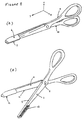
- the Grip-cut tool 1 of Figure 1(A) has component bodies 2 and 3 with cutting edge blades 4 and 5 respectively, with body 2 mounting gripping member 6 and body 3 mounting gripping member 7.
- Contact of element 11 of member 6 against member 7 actions the gripping when the tool is placed in the closed position.
- This closing action also causes the blades 4 and 5 to co-act in a cutting motion that will cause any material placed between the blades 4 and 5 to be cut.
- Opening and closure of handles 9 and 10 causes an arcuate movement of bodies 2 and 3 respectively, with resultant opening and closure of 2 and 3 and also 6 and 7.
- Figure 1(B) shows the tool in the open position, whereas 1(A) showed the tool in the closed position.
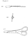
- Figure 2 shows a second embodiment of the invention, with it closed in Fig 2(A) and open at Fig 2(B), of the type that can be used to cut flex, steel wire, etc.
- Fig 2(A) has like reference numerals to the embodiment shown in Figure 1.
- This tool also opens and closes via a pivoting hinge.
- Figure 3 shows a preferred embodiment of the invention for suture removal.
- 3(A) shows the tool in the closed position, and at (B) in the open position, with the serrated area 12 being the grip surface against which element 11 comes into contact when the tool is in the closed position, allowing the object being cut to be gripped firmly during and after cutting.
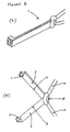
- Figure 4 shows at (A), (B) and (C) views of the embodiment shown in Figure 3(A) from each of the three mutually orthogonal directions X, Y and Z that are marked in Fig. 3(A).
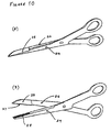
- Figure 5 shows a stylised embodiment of the invention in the closed position at (A) and in the open position at (B).
- Figure 6 shows yet another stylised embodiment of the invention wherein there are provided two pairs of gripping members 6 and 7 on either planar side of the invention, so that gripping surfaces 11 and 12 exist on both sides of the longitudinal axis of the cutting blades 4 and 5, allowing both cut ends of the object being cut to be gripped.
- Figure 7 shows a plan view of yet another, preferred, embodiment of the invention (wit 7A, 7B and 7C showing views of this embodiment from one side, from above, and from the front respectively) when incorporated into a notched style of suture scissors 14.
- the concave notch 15 borne on the upper, cutting-edge, border of one shear body 17 is modified to bear a gripping surface (such that the gripping surface existing in a concave plane), with a complementary convex gripping element 16 (with a gripping surface arranged on a curved and convex plane) incorporated into the other, opposing, co-acting, shear body 18.
- a further embodiment of this invention when part of a notched suture scissors manifestation requires only one gripping member 16, on the non-notched shear body 18, as the upper border of the notch 15 on the notch-bearing shear body 17, acts as the opposing gripping element, as shown in Figure 7.
- the gripping element located on the non-notched shear body has a gripping surface that grips against the upper border of the notch and the non-adjacent blade side of the shear body.
- the gripping surfaces on the notched shear body are the surfaces of the upper border of the notch and part of the side of the shear body that does not touch with or contact with the opposing co-acting shear body (the side of the shear body that is not adjacent to the other co-acting shear body).
- both shear bodies have gripping elements in which the gripping surfaces of each exist in two or more planes. This is shown in Figure 10.
- gripping elements may incorporate gripping members with rounded or domed gripping surfaces that fit into a complementary dish-like hollow, a V-shaped notch bearing gripping surfaces designed to accept and be complementary to the gripping surfaces on a triangular tooth that intimately engages with the V-shaped notch, other types and styles of toothed elements complementary to and designed to fit into complementary recesses, or other types of gripping, co-acting, member.
- a plurality of co-acting blades and gripping member arrangements may be provided on a single device.
Landscapes
- Health & Medical Sciences (AREA)
- Surgery (AREA)
- Life Sciences & Earth Sciences (AREA)
- Medical Informatics (AREA)
- Animal Behavior & Ethology (AREA)
- Engineering & Computer Science (AREA)
- Biomedical Technology (AREA)
- Heart & Thoracic Surgery (AREA)
- Veterinary Medicine (AREA)
- Molecular Biology (AREA)
- Nuclear Medicine, Radiotherapy & Molecular Imaging (AREA)
- General Health & Medical Sciences (AREA)
- Public Health (AREA)
- Orthopedic Medicine & Surgery (AREA)
- Pathology (AREA)
- Ophthalmology & Optometry (AREA)
- Scissors And Nippers (AREA)
Applications Claiming Priority (1)
| Application Number | Priority Date | Filing Date | Title |
|---|---|---|---|
| GB0411520A GB2412344B (en) | 2004-02-05 | 2004-05-24 | Gripcut tool |
Publications (2)
| Publication Number | Publication Date |
|---|---|
| EP1656893A2 true EP1656893A2 (fr) | 2006-05-17 |
| EP1656893A3 EP1656893A3 (fr) | 2006-06-07 |
Family
ID=35735251
Family Applications (1)
| Application Number | Title | Priority Date | Filing Date |
|---|---|---|---|
| EP05253156A Withdrawn EP1656893A3 (fr) | 2004-05-24 | 2005-05-23 | Outil de préhension et de coupe combiné |
Country Status (2)
| Country | Link |
|---|---|
| US (1) | US20060260135A1 (fr) |
| EP (1) | EP1656893A3 (fr) |
Cited By (5)
| Publication number | Priority date | Publication date | Assignee | Title |
|---|---|---|---|---|
| CN101313866B (zh) * | 2008-07-17 | 2010-04-14 | 成都峻峰科技开发有限公司 | 夹拉式手术剪 |
| WO2010030832A3 (fr) * | 2008-09-12 | 2010-07-15 | Dr. Slick Company | Appareil d'articulation d'outil à main à poignée décalée |
| ITBZ20110011A1 (it) * | 2011-03-31 | 2012-10-01 | Walter Bellini | Strumento per l'estrazione di fili di suture chirurgiche perfezionato. |
| CN104382621A (zh) * | 2014-12-15 | 2015-03-04 | 雷钧皓 | 用于拆除伤口缝合线的外科拆线剪 |
| US20220395916A1 (en) * | 2018-04-10 | 2022-12-15 | Hubbell Incorporated | Portable in-line cutting tool with stabilizer |
Families Citing this family (7)
| Publication number | Priority date | Publication date | Assignee | Title |
|---|---|---|---|---|
| CN102599950A (zh) * | 2012-03-15 | 2012-07-25 | 马光元 | 存留线头自动测量剪 |
| US10123605B2 (en) * | 2014-12-10 | 2018-11-13 | Linda Luu | Hair cutting device |
| US10456126B2 (en) * | 2015-10-05 | 2019-10-29 | Chris Geiger | Forceps with integrated blade |
| CN106037887A (zh) * | 2016-07-04 | 2016-10-26 | 宋养荣 | 一种食道癌手术用剪切刀 |
| KR102142644B1 (ko) * | 2018-11-07 | 2020-08-07 | 한림대학교 산학협력단 | 의료용 강선 제거장치 |
| US10730194B2 (en) * | 2019-01-08 | 2020-08-04 | Diana Jean Marble | Sewer's multi-tool assembly |
| CN116035645A (zh) * | 2022-11-10 | 2023-05-02 | 贵州省黔南布依族苗族自治州中医医院 | 一种用于脊柱手术的黄韧带刨削刀及其使用方法 |
Family Cites Families (5)
| Publication number | Priority date | Publication date | Assignee | Title |
|---|---|---|---|---|
| US2865099A (en) * | 1956-07-03 | 1958-12-23 | Robert C Blackwood | Scissor instrument |
| US3443313A (en) * | 1967-07-03 | 1969-05-13 | Profy Albert T | Hemostat for cutting and removing sutures |
| US4428374A (en) * | 1978-12-20 | 1984-01-31 | Auburn Robert M | Umbilical cord clamping assembly |
| US4246698A (en) * | 1979-07-20 | 1981-01-27 | Laschal Instruments Corp. | Suture remover |
| GB2345857B (en) * | 1999-01-23 | 2000-12-06 | Ahmad Fahmi Juanroyee | Scissors-clip diathermy (SCD) |
-
2005
- 2005-05-23 EP EP05253156A patent/EP1656893A3/fr not_active Withdrawn
- 2005-09-21 US US11/330,991 patent/US20060260135A1/en not_active Abandoned
Cited By (6)
| Publication number | Priority date | Publication date | Assignee | Title |
|---|---|---|---|---|
| CN101313866B (zh) * | 2008-07-17 | 2010-04-14 | 成都峻峰科技开发有限公司 | 夹拉式手术剪 |
| WO2010030832A3 (fr) * | 2008-09-12 | 2010-07-15 | Dr. Slick Company | Appareil d'articulation d'outil à main à poignée décalée |
| US8272300B2 (en) | 2008-09-12 | 2012-09-25 | Dr. Slick Company | Hand tool articulating apparatus with offset handle |
| ITBZ20110011A1 (it) * | 2011-03-31 | 2012-10-01 | Walter Bellini | Strumento per l'estrazione di fili di suture chirurgiche perfezionato. |
| CN104382621A (zh) * | 2014-12-15 | 2015-03-04 | 雷钧皓 | 用于拆除伤口缝合线的外科拆线剪 |
| US20220395916A1 (en) * | 2018-04-10 | 2022-12-15 | Hubbell Incorporated | Portable in-line cutting tool with stabilizer |
Also Published As
| Publication number | Publication date |
|---|---|
| EP1656893A3 (fr) | 2006-06-07 |
| US20060260135A1 (en) | 2006-11-23 |
Similar Documents
| Publication | Publication Date | Title |
|---|---|---|
| US4246698A (en) | Suture remover | |
| US4669470A (en) | Surgical forceps/scissors | |
| EP1353783B1 (fr) | Outil de coupe universel pourvu d'un mecanisme d'articulation demultipliee | |
| US5015252A (en) | Surgical forceps with suture cutters | |
| US7458160B2 (en) | Ergonomic handle for scissors and other tools | |
| EP1656893A2 (fr) | Outil de préhension et de coupe combiné | |
| US3659343A (en) | Suture cutter | |
| EP2160273B1 (fr) | Paire de ciseaux à usages multiples | |
| CA2596078A1 (fr) | Organe effecteur destine a un instrument chirurgical, instrument chirurgical, et procede de formation de cet organe effecteur | |
| CN1160008C (zh) | 指甲钳 | |
| US5119561A (en) | Pivoted sqeeze tool | |
| US3287751A (en) | Plier-type cutting and gripping tool | |
| US5881461A (en) | Nail cutter/clipper for treating ingrown nails and hang nails and/or preventing ingrown nails | |
| GB2412344A (en) | Grip-cut tool | |
| US6733508B1 (en) | Umbilical cord clamp cutter | |
| US20170080584A1 (en) | Scissors | |
| US11778952B2 (en) | Shearing device providing a pair of pincers for securing the sheared object | |
| CN214712695U (zh) | 一种弹簧锤骨剪 | |
| EP4197461B1 (fr) | Instrument médical | |
| CN106455522A (zh) | 动物爪子修剪设备及其使用方法 | |
| GB2410689A (en) | Dental luxator | |
| WO1995015078A9 (fr) | Outil de coupe | |
| JP3130425U (ja) | 鋸歯と切刃とを併せもつ剪定鋏 | |
| WO1995015078A2 (fr) | Outil de coupe | |
| JP4041533B2 (ja) | 爪整形具 |
Legal Events
| Date | Code | Title | Description |
|---|---|---|---|
| PUAI | Public reference made under article 153(3) epc to a published international application that has entered the european phase |
Free format text: ORIGINAL CODE: 0009012 |
|
| PUAL | Search report despatched |
Free format text: ORIGINAL CODE: 0009013 |
|
| AK | Designated contracting states |
Kind code of ref document: A2 Designated state(s): AT BE BG CH CY CZ DE DK EE ES FI FR GB GR HU IE IS IT LI LT LU MC NL PL PT RO SE SI SK TR |
|
| AX | Request for extension of the european patent |
Extension state: AL BA HR LV MK YU |
|
| AK | Designated contracting states |
Kind code of ref document: A3 Designated state(s): AT BE BG CH CY CZ DE DK EE ES FI FR GB GR HU IE IS IT LI LT LU MC NL PL PT RO SE SI SK TR |
|
| AX | Request for extension of the european patent |
Extension state: AL BA HR LV MK YU |
|
| RIC1 | Information provided on ipc code assigned before grant |
Ipc: A61B 17/04 20060101ALI20060421BHEP Ipc: A61B 17/32 20060101ALI20060421BHEP Ipc: A61B 17/28 20060101AFI20060214BHEP |
|
| AKX | Designation fees paid |
Designated state(s): AT BE BG CH LI |
|
| REG | Reference to a national code |
Ref country code: DE Ref legal event code: 8566 |
|
| STAA | Information on the status of an ep patent application or granted ep patent |
Free format text: STATUS: THE APPLICATION IS DEEMED TO BE WITHDRAWN |
|
| 18D | Application deemed to be withdrawn |
Effective date: 20061208 |