EP1656973A1 - Vorrichtung zur Montage der Teile einer Sicherheitsbindung auf einem Ski - Google Patents
Vorrichtung zur Montage der Teile einer Sicherheitsbindung auf einem Ski Download PDFInfo
- Publication number
- EP1656973A1 EP1656973A1 EP05300825A EP05300825A EP1656973A1 EP 1656973 A1 EP1656973 A1 EP 1656973A1 EP 05300825 A EP05300825 A EP 05300825A EP 05300825 A EP05300825 A EP 05300825A EP 1656973 A1 EP1656973 A1 EP 1656973A1
- Authority
- EP
- European Patent Office
- Prior art keywords
- platform
- ski
- rigid platform
- rear plate
- plate
- Prior art date
- Legal status (The legal status is an assumption and is not a legal conclusion. Google has not performed a legal analysis and makes no representation as to the accuracy of the status listed.)
- Granted
Links
- 230000027455 binding Effects 0.000 title claims description 15
- 238000009739 binding Methods 0.000 title claims description 15
- 239000013536 elastomeric material Substances 0.000 claims description 5
- 238000005452 bending Methods 0.000 description 5
- 238000013016 damping Methods 0.000 description 4
- 230000000694 effects Effects 0.000 description 4
- 238000006073 displacement reaction Methods 0.000 description 3
- 230000000903 blocking effect Effects 0.000 description 2
- 230000000295 complement effect Effects 0.000 description 2
- 238000001804 debridement Methods 0.000 description 2
- 239000000463 material Substances 0.000 description 2
- 230000000284 resting effect Effects 0.000 description 2
- 239000003190 viscoelastic substance Substances 0.000 description 2
- 229910001008 7075 aluminium alloy Inorganic materials 0.000 description 1
- 229910045601 alloy Inorganic materials 0.000 description 1
- 239000000956 alloy Substances 0.000 description 1
- 229910052782 aluminium Inorganic materials 0.000 description 1
- XAGFODPZIPBFFR-UHFFFAOYSA-N aluminium Chemical compound [Al] XAGFODPZIPBFFR-UHFFFAOYSA-N 0.000 description 1
- 238000004873 anchoring Methods 0.000 description 1
- 230000006835 compression Effects 0.000 description 1
- 238000007906 compression Methods 0.000 description 1
- 239000000835 fiber Substances 0.000 description 1
- 238000003754 machining Methods 0.000 description 1
- 229910052751 metal Inorganic materials 0.000 description 1
- 239000002184 metal Substances 0.000 description 1
- 238000000034 method Methods 0.000 description 1
- 239000004033 plastic Substances 0.000 description 1
- 229920003023 plastic Polymers 0.000 description 1
- 230000000630 rising effect Effects 0.000 description 1
- XLYOFNOQVPJJNP-UHFFFAOYSA-N water Substances O XLYOFNOQVPJJNP-UHFFFAOYSA-N 0.000 description 1
Images


Classifications
-
- A—HUMAN NECESSITIES
- A63—SPORTS; GAMES; AMUSEMENTS
- A63C—SKATES; SKIS; ROLLER SKATES; DESIGN OR LAYOUT OF COURTS, RINKS OR THE LIKE
- A63C9/00—Ski bindings
- A63C9/003—Non-swivel sole plate fixed on the ski
-
- A—HUMAN NECESSITIES
- A63—SPORTS; GAMES; AMUSEMENTS
- A63C—SKATES; SKIS; ROLLER SKATES; DESIGN OR LAYOUT OF COURTS, RINKS OR THE LIKE
- A63C9/00—Ski bindings
- A63C9/005—Ski bindings with means for adjusting the position of a shoe holder or of the complete binding relative to the ski
Definitions
- the invention relates to the field of snow sports, especially Alpine skiing. It relates more specifically to a mounting device on a ski elements of a safety binding, namely the heel and the stop.
- the intermediate devices also make it possible to raise the fastening, and to facilitate tilting from one edge to the other, as described in document EP 0 409 749.
- these intermediate devices are also used to ensure debridement, that is to say, to limit the influence of the stiffness of the sole of the boot on the behavior of the ski
- a part of the platform can be made movable relative to the upper face of the ski, being mounted with a sliding capacity with respect to a fixed point integral with the upper face of the ski.
- the invention therefore relates to a device for mounting the elements of a safety binding on a ski.
- the heel of the binding is mounted on the rear plate which itself rests on the upper face of the platform by stepping laterally thereof, and thus allowing the entire platform / back plate to move longitudinally by compared to skiing.
- This movement is however limited by the presence of stops, including the rear stop, which prevents the excessive sliding of the platform to the rear.
- this rear plate may comprise portions extending downwardly on each side of the platform, and intended to come into close contact with the upper face of the ski. These characteristic portions thus define between them a channel inside which is embedded the rigid platform.
- the rigid platform may include lateral recesses, interrupting the slideways, so as to allow the passage of the portions of the rear plate which extend downwardly and which come into close contact with the upper face of the ski. These recesses thus allow the introduction of this back plate above the platform, while allowing the longitudinal displacement of the back plate relative to the holding elements.
- the abutment of the fastener can be secured either directly on the rigid platform, or advantageously on a front plate, secured to the rigid platform by arrangements provided for this purpose.
- this front plate can be made slidable relative to the rigid platform, to allow the attachment to the platform in different longitudinal adjustment positions. In this way, the adjustment of the position of the stop is done by moving the front plate, and blocking it on the platform in the desired position.
- This front plate can advantageously come into contact with the upper face of the ski by stepping laterally rigid platform, so as to transmit the support exerted on the stop to the board. This eliminates the damping effect generated by the presence of the elastomeric material element located under the rigid platform.
- This element of elastomeric material may advantageously comprise a protruding zone interposed between the rear end of the rigid platform and the rear stop.
- This area thus rising between the fixed point of the rear stop and the platform provides a damping effect when moving the rigid platform following the bending of the ski.
- the platform may advantageously have a tubular structure, defining longitudinal channels so as to maintain good torsional stiffness while limiting the overall weight.
- the platform may have in the central part transverse recesses formed on its underside, and intended to reduce its stiffness in flexion.
- Figure 1 illustrates the assembly of the device (1) for mounting the elements of the binding (not shown) on the ski (2).
- the mounting device (1) comprises a rigid platform (3), which rests on a member (4) of viscoelastic material, itself resting on the upper face of the ski (2).
- the front (6) and rear (5) stops cooperate with the ends of the rigid platform (3).
- This rigid platform receives on its upper face a rear plate (7) for receiving the heel (not shown), while a front plate (8) is provided to receive the stop (not shown) of the binding.
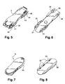
- the rigid platform (3) has a tubular structure, and comprises channels (10, 11) extending over the entire length of the platform and thus allowing the latter to be made from of a profile.
- This profile can be made of metal, for example aluminum-based alloy such as Zicral® , or else based on fiber-filled plastics material.
- the platform (3) has laterally two rails formed by a groove (12) extending longitudinally on the side of the platform (3).
- these slides can be made differently, and in particular by a narrowing of the width of the platform defining a rail adapted to receive protruding areas of the member intended to slide on the platform.
- the platform (3) has recesses (15) for reducing the bending stiffness of the rigid platform (3). These recesses are made by machining the profile forming the platform (3). These recesses (15) are intended to be filled by bosses (16) made on the upper face of the elastomeric element (4). These bosses (16) are intended to be compressed during bending movements of the platform (3), and to confer damping or spring properties depending on the material used.
- the platform (3) In its front part, the platform (3) has holes for receiving the mounting screws (18) on the upper face of the board.
- the platform (3) also comprises a plurality of central bores (19) for receiving the locking screw (20) of the front plate (8).
- a plurality of holes (19) makes it possible to adjust the longitudinal position of the front plate (8) as a function of the length of the boot.
- the rigid platform (3) On its underside, the rigid platform (3) has grooves (21), arranged laterally and intended to receive ribs (22) formed on the upper face of the elastomeric layer (4).
- These ribs make it possible in particular to limit the passage of snow and water, and especially avoid the lateral escape of the elastomeric layer (4).
- These ribs (22) also constitute a compressible zone capable of providing a damping effect.
- the elastomeric layer (4) has a bulge (25) for receiving on its front face the supports and the rear ends of the platform (3).
- This bulge (25) is pierced longitudinally by an opening (26) for receiving a portion (28) facing the front of the rear stop (5).
- this portion (28) passes through the recess (26), and penetrates inside the central channel (27). ) of the rigid platform (3). The lateral movement of the platform is avoided.
- the longitudinal deflection of the platform is limited by the compression of the protruding zone (25) between the rear end of the platform (3) and the rear stop (5) itself secured to the upper face of the ski by the screw ( 30).
- the rear part of the platform (3) has a longitudinal displacement capacity conferred by the architecture of the rear plate (7).
- this rear plate (7) has an upper face (32) for receiving the heel via screwings in the holes (33).
- the rear plate (7) has downwardly extending portions (34,35) on its underside so as to come into close contact with the upper face of the ski (2). There is thus a small clearance between the rear plate and the upper face of the ski, to avoid excessive friction during bending of the ski. Between these two sides of the rear plate (7), these portions (35, 36) define a channel inside which the platform (3) is inserted. As shown in FIG. 6, the internal faces of these portions (34, 35) comprise bulges (36, 37) intended to fit into the recesses (38, 39) made on the sides of the rigid platform (3, 3). ).
- the back plate is secured to the platform for longitudinal movements.
- This blocking is completed by the presence of the stud (48) prominent under the underside of the back plate, and which fits into the housing (58) formed on the upper face of the rigid platform.
- the back plate (7) has recesses (40, 41) receiving complementary pieces (42, 44).
- the parts (42, 44) disposed at the rear of the plate (7) comprise in the lower part a gun (45) adapted to receive the fixing screws (47).
- This barrel (45) penetrates inside a recess (46) which has larger longitudinal dimensions, so that the rear plate (7) can move longitudinally with respect to the fixed point constituted by the mounting screw ( 47), under the effect of the displacement of the platform (3).
- the shapes of the attachment piece (42, 44), including the recess (49) are provided to allow this longitudinal movement.
- the barrels (50) of the complementary piece (43) have a length in the longitudinal direction which is less than that of the recess (51) which receives them.
- the device according to the invention comprises an abutment (6) closing off the channels (10, 11) of the platform (3), and constitute a piece of appearance resting on the front of the elastomeric layer (4).
- This abutment (6) is held in position by embedding with a prominent region (59) of the elastomeric layer (4).
- the front plate (8) has lateral portions (55, 56) which extend vertically and extend in contact with the upper face of the board.
- lateral portions (55, 56) have on the inner face guides (57) intended to cooperate with the slide (12) of the rigid platform (3) during the adjustment in longitudinal position of the front plate on said platform (3) .
- the rigid platform (3) is firmly fixed by its front end on the upper face of the ski (2).
- the rear part of the platform is slidable relative to the upper face of the ski.
- the rear plate (7) has a longitudinal sliding capacity relative to the fixed point constituted by the mounting screws (47), thanks to the elongate shape of the recesses (46). It follows that during bending, the rear plate is slightly offset backwards by the movement of the platform whose deformations are significantly lower than those of the ski.
- the behavior of the skis equipped with the invention is particularly improved. Indeed, it was observed that by moving the rear plate / platform assembly, the ski deforms at best to fit into the curve of the turn. The hooking power and the pressure on the sidecut are thus increased, regardless of the type of turn.
Landscapes
- Footwear And Its Accessory, Manufacturing Method And Apparatuses (AREA)
- Fittings On The Vehicle Exterior For Carrying Loads, And Devices For Holding Or Mounting Articles (AREA)
- Motorcycle And Bicycle Frame (AREA)
- Portable Nailing Machines And Staplers (AREA)
Applications Claiming Priority (1)
| Application Number | Priority Date | Filing Date | Title |
|---|---|---|---|
| FR0452602A FR2877850B1 (fr) | 2004-11-12 | 2004-11-12 | Dispositif de montage des elements d'une fixation de securite sur un ski |
Publications (2)
| Publication Number | Publication Date |
|---|---|
| EP1656973A1 true EP1656973A1 (de) | 2006-05-17 |
| EP1656973B1 EP1656973B1 (de) | 2008-03-19 |
Family
ID=34950519
Family Applications (1)
| Application Number | Title | Priority Date | Filing Date |
|---|---|---|---|
| EP05300825A Expired - Lifetime EP1656973B1 (de) | 2004-11-12 | 2005-10-14 | Vorrichtung zur Montage der Teile einer Sicherheitsbindung auf einem Ski |
Country Status (5)
| Country | Link |
|---|---|
| US (1) | US7513509B2 (de) |
| EP (1) | EP1656973B1 (de) |
| AT (1) | ATE389443T1 (de) |
| DE (1) | DE602005005420T2 (de) |
| FR (1) | FR2877850B1 (de) |
Families Citing this family (7)
| Publication number | Priority date | Publication date | Assignee | Title |
|---|---|---|---|---|
| FR2901486A1 (fr) * | 2006-05-24 | 2007-11-30 | Salomon Sa | Ensemble comprenant une planche de glisse et un dispositif de retenue d'un article chaussant sur la planche |
| AT11239U1 (de) * | 2008-11-03 | 2010-07-15 | Atomic Austria Gmbh | Schibindung mit einer positionier- und fixiervorrichtung für deren backenkörper |
| AT507579B1 (de) * | 2008-12-11 | 2011-01-15 | Atomic Austria Gmbh | Schi oder snowboard mit einem plattenartigen kraftübertragungselement |
| USD733243S1 (en) * | 2013-09-20 | 2015-06-30 | Rottefella As | Ski binding |
| US20170173443A1 (en) * | 2014-03-31 | 2017-06-22 | Vist Tech S.R.L. | Ski binding |
| NO342933B1 (no) | 2017-05-30 | 2018-09-03 | Rottefella As | Festemekanisme for et låseorgan som skal festes til en monteringsplate på en langrennsski |
| JP7577397B1 (ja) | 2024-06-20 | 2024-11-05 | 株式会社小賀坂スキー製作所 | ガイド部材及びスキー板用剛性調節装置 |
Citations (8)
| Publication number | Priority date | Publication date | Assignee | Title |
|---|---|---|---|---|
| EP0409749A1 (de) | 1989-07-18 | 1991-01-23 | Skis Rossignol S.A. | Zusatzvorrichtung zum Ski zur Montage eines Paares Skibindungen auf dem Ski |
| FR2664823A1 (fr) | 1990-07-19 | 1992-01-24 | Rossignol Sa | Ski alpin. |
| FR2695041A1 (fr) * | 1992-08-31 | 1994-03-04 | Anesi Tullio | Elément de liaison adaptable entre ski et fixation de ski. |
| FR2713101A1 (fr) * | 1993-11-30 | 1995-06-09 | Rossignol Sa | Accessoire pour plaque montée sur la face supérieure d'un ski alpin et destinée à recevoir la fixation d'une chaussure. |
| FR2731358A1 (fr) * | 1995-03-10 | 1996-09-13 | Salomon Sa | Dispositif destine a modifier la repartition naturelle d'un ski sur sa surface de glisse |
| FR2809634A1 (fr) | 2000-05-31 | 2001-12-07 | Rossignol Sa | Dispositif de rehaussement destine a etre monte sur une planche de glisse |
| US20020047250A1 (en) * | 2000-09-11 | 2002-04-25 | Max Luitz | Binding support plate and board-type runner for same |
| FR2820335A1 (fr) | 2001-02-02 | 2002-08-09 | Rossignol Sa | Plaque interface destinee a etre solidarisee a la face superieure d'un ski |
Family Cites Families (4)
| Publication number | Priority date | Publication date | Assignee | Title |
|---|---|---|---|---|
| FR2698013B1 (fr) * | 1992-11-19 | 1994-12-16 | Rossignol Sa | Dispositif de montage d'une chaussure sur un ski alpin. |
| US5785342A (en) * | 1996-07-30 | 1998-07-28 | Bronson; Henry D. | Ski binding dampening assembly |
| FR2785823B1 (fr) * | 1998-11-13 | 2001-03-02 | Salomon Sa | Engin de glisse comprenant un dispositif d'interface de fixations relie a un ski |
| EP1314458A1 (de) * | 2001-11-23 | 2003-05-28 | HTM Sport- und Freizeitgeräte Aktiengesellschaft | Anordnung für eine auf einem Ski positionierbare Skibindung |
-
2004
- 2004-11-12 FR FR0452602A patent/FR2877850B1/fr not_active Expired - Fee Related
-
2005
- 2005-10-14 EP EP05300825A patent/EP1656973B1/de not_active Expired - Lifetime
- 2005-10-14 AT AT05300825T patent/ATE389443T1/de not_active IP Right Cessation
- 2005-10-14 DE DE602005005420T patent/DE602005005420T2/de not_active Expired - Lifetime
- 2005-11-14 US US11/271,958 patent/US7513509B2/en not_active Expired - Fee Related
Patent Citations (8)
| Publication number | Priority date | Publication date | Assignee | Title |
|---|---|---|---|---|
| EP0409749A1 (de) | 1989-07-18 | 1991-01-23 | Skis Rossignol S.A. | Zusatzvorrichtung zum Ski zur Montage eines Paares Skibindungen auf dem Ski |
| FR2664823A1 (fr) | 1990-07-19 | 1992-01-24 | Rossignol Sa | Ski alpin. |
| FR2695041A1 (fr) * | 1992-08-31 | 1994-03-04 | Anesi Tullio | Elément de liaison adaptable entre ski et fixation de ski. |
| FR2713101A1 (fr) * | 1993-11-30 | 1995-06-09 | Rossignol Sa | Accessoire pour plaque montée sur la face supérieure d'un ski alpin et destinée à recevoir la fixation d'une chaussure. |
| FR2731358A1 (fr) * | 1995-03-10 | 1996-09-13 | Salomon Sa | Dispositif destine a modifier la repartition naturelle d'un ski sur sa surface de glisse |
| FR2809634A1 (fr) | 2000-05-31 | 2001-12-07 | Rossignol Sa | Dispositif de rehaussement destine a etre monte sur une planche de glisse |
| US20020047250A1 (en) * | 2000-09-11 | 2002-04-25 | Max Luitz | Binding support plate and board-type runner for same |
| FR2820335A1 (fr) | 2001-02-02 | 2002-08-09 | Rossignol Sa | Plaque interface destinee a etre solidarisee a la face superieure d'un ski |
Also Published As
| Publication number | Publication date |
|---|---|
| EP1656973B1 (de) | 2008-03-19 |
| DE602005005420T2 (de) | 2009-03-05 |
| US7513509B2 (en) | 2009-04-07 |
| US20060103113A1 (en) | 2006-05-18 |
| FR2877850A1 (fr) | 2006-05-19 |
| FR2877850B1 (fr) | 2006-12-08 |
| DE602005005420D1 (de) | 2008-04-30 |
| ATE389443T1 (de) | 2008-04-15 |
Similar Documents
| Publication | Publication Date | Title |
|---|---|---|
| EP0409749B1 (de) | Zusatzvorrichtung zum Ski zur Montage eines Paares Skibindungen auf dem Ski | |
| EP1563876B1 (de) | Langlaufski | |
| EP1129747B1 (de) | Keilförmiges Element für eine Snowboardbindung | |
| EP1000641A1 (de) | Gleitgerät mit ein Bindungsträgerplatte an einem Ski | |
| EP1656974B1 (de) | Einrichtung zur Montage von Sicherheitsbindungsteilen auf einen Ski | |
| EP1166834B1 (de) | Alpinski | |
| EP1656973B1 (de) | Vorrichtung zur Montage der Teile einer Sicherheitsbindung auf einem Ski | |
| EP1228787A1 (de) | Unterlagsplatte zur Verbindung an der oberen Oberfläche eines Skis | |
| EP1234604B1 (de) | Trägerplatte für ein Snowboard | |
| EP1508352B1 (de) | Snowboardbindung | |
| EP1013316B1 (de) | Alpinski | |
| EP1155716A1 (de) | Vorrichtung zum Erhöhen von mindestens einer Ski Bindung zur Verwendung auf einem Gleitbrett | |
| FR2674444A1 (fr) | Cales interface pour fixation de securite de ski alpin. | |
| EP1013317A1 (de) | Schneegleitbrett | |
| EP1166669B1 (de) | Snowboardstiefel | |
| EP1159990A1 (de) | Trägerplatte für ein Snowboard | |
| EP2465588B1 (de) | Montagevorrichtung auf einem Ski für die Elemente einer Sicherheitsskibindung | |
| FR2796852A1 (fr) | Dispositif interface entre une chaussure et un ski | |
| WO2002085473A1 (fr) | Dispositif de montage, demontage rapides d'une fixation de ski sur un ski | |
| EP2732857B1 (de) | Zehenhalter einer Skibindung, und Skibindungssystem, das mit einem solchen Zehenhalter ausgestattet ist | |
| FR2713102A1 (fr) | Surf sur neige. | |
| EP1479417B1 (de) | Snowboardbindung | |
| FR2815879A1 (fr) | Plate-forme de rehaussement destinee a etre ancree sur un ski | |
| FR2800625A1 (fr) | Ski alpin | |
| FR2768937A1 (fr) | Plot amortisseur destine a etre monte sur un article de sport, tel que notamment un ski equipe d'une plate-forme ou une platine de patin a roulettes |
Legal Events
| Date | Code | Title | Description |
|---|---|---|---|
| PUAI | Public reference made under article 153(3) epc to a published international application that has entered the european phase |
Free format text: ORIGINAL CODE: 0009012 |
|
| AK | Designated contracting states |
Kind code of ref document: A1 Designated state(s): AT BE BG CH CY CZ DE DK EE ES FI FR GB GR HU IE IS IT LI LT LU LV MC NL PL PT RO SE SI SK TR |
|
| AX | Request for extension of the european patent |
Extension state: AL BA HR MK YU |
|
| 17P | Request for examination filed |
Effective date: 20060727 |
|
| AKX | Designation fees paid |
Designated state(s): AT DE FR |
|
| GRAP | Despatch of communication of intention to grant a patent |
Free format text: ORIGINAL CODE: EPIDOSNIGR1 |
|
| GRAS | Grant fee paid |
Free format text: ORIGINAL CODE: EPIDOSNIGR3 |
|
| GRAA | (expected) grant |
Free format text: ORIGINAL CODE: 0009210 |
|
| AK | Designated contracting states |
Kind code of ref document: B1 Designated state(s): AT DE FR |
|
| REF | Corresponds to: |
Ref document number: 602005005420 Country of ref document: DE Date of ref document: 20080430 Kind code of ref document: P |
|
| PLBE | No opposition filed within time limit |
Free format text: ORIGINAL CODE: 0009261 |
|
| STAA | Information on the status of an ep patent application or granted ep patent |
Free format text: STATUS: NO OPPOSITION FILED WITHIN TIME LIMIT |
|
| 26N | No opposition filed |
Effective date: 20081222 |
|
| PGFP | Annual fee paid to national office [announced via postgrant information from national office to epo] |
Ref country code: AT Payment date: 20080918 Year of fee payment: 4 |
|
| PGFP | Annual fee paid to national office [announced via postgrant information from national office to epo] |
Ref country code: DE Payment date: 20091016 Year of fee payment: 5 |
|
| PGFP | Annual fee paid to national office [announced via postgrant information from national office to epo] |
Ref country code: FR Payment date: 20091116 Year of fee payment: 5 |
|
| PG25 | Lapsed in a contracting state [announced via postgrant information from national office to epo] |
Ref country code: AT Free format text: LAPSE BECAUSE OF NON-PAYMENT OF DUE FEES Effective date: 20091014 |
|
| PG25 | Lapsed in a contracting state [announced via postgrant information from national office to epo] |
Ref country code: FR Free format text: LAPSE BECAUSE OF NON-PAYMENT OF DUE FEES Effective date: 20101102 |
|
| REG | Reference to a national code |
Ref country code: FR Ref legal event code: ST Effective date: 20110630 |
|
| REG | Reference to a national code |
Ref country code: DE Ref legal event code: R119 Ref document number: 602005005420 Country of ref document: DE Effective date: 20110502 |
|
| PG25 | Lapsed in a contracting state [announced via postgrant information from national office to epo] |
Ref country code: DE Free format text: LAPSE BECAUSE OF NON-PAYMENT OF DUE FEES Effective date: 20110502 |