EP1657009A1 - Amélioration d'une buse de coulée immergée pour la coulée continue de l'acier - Google Patents
Amélioration d'une buse de coulée immergée pour la coulée continue de l'acier Download PDFInfo
- Publication number
- EP1657009A1 EP1657009A1 EP04425844A EP04425844A EP1657009A1 EP 1657009 A1 EP1657009 A1 EP 1657009A1 EP 04425844 A EP04425844 A EP 04425844A EP 04425844 A EP04425844 A EP 04425844A EP 1657009 A1 EP1657009 A1 EP 1657009A1
- Authority
- EP
- European Patent Office
- Prior art keywords
- flow
- mould
- diffuser
- nozzle
- section
- Prior art date
- Legal status (The legal status is an assumption and is not a legal conclusion. Google has not performed a legal analysis and makes no representation as to the accuracy of the status listed.)
- Withdrawn
Links
- 238000009749 continuous casting Methods 0.000 title claims 2
- 229910000831 Steel Inorganic materials 0.000 title 1
- 239000010959 steel Substances 0.000 title 1
- 239000000956 alloy Substances 0.000 claims abstract 2
- 229910045601 alloy Inorganic materials 0.000 claims abstract 2
- 238000001816 cooling Methods 0.000 claims abstract 2
- 239000012530 fluid Substances 0.000 claims abstract 2
- 230000005484 gravity Effects 0.000 claims abstract 2
- 239000002184 metal Substances 0.000 claims abstract 2
- 238000009792 diffusion process Methods 0.000 claims 5
- 210000003462 vein Anatomy 0.000 claims 2
- 238000007598 dipping method Methods 0.000 claims 1
- 239000007788 liquid Substances 0.000 claims 1
- 230000001105 regulatory effect Effects 0.000 claims 1
- 230000015572 biosynthetic process Effects 0.000 abstract 1
Images

Classifications
-
- B—PERFORMING OPERATIONS; TRANSPORTING
- B22—CASTING; POWDER METALLURGY
- B22D—CASTING OF METALS; CASTING OF OTHER SUBSTANCES BY THE SAME PROCESSES OR DEVICES
- B22D41/00—Casting melt-holding vessels, e.g. ladles, tundishes, cups or the like
- B22D41/50—Pouring-nozzles
Definitions
- the present invention relates to a feed pipe or submerged nozzle for the continuous casting of semifinished steel products such as slabs, either thin (50-70 mm thick) or almost thin (70-120 mm thick) or conventional (120-450 mm thick) ones, and for steel flows up to 8 ton/min as required for example in continuous casting for thin slabs at high speed (>5 m/min) and in continuous casting/roughing processes, wherein it is desired to solidify a flow rate of steel as above indicated and comparable to that of a continuous heat laminating-finishing train for strips, so as to line up both processes without any interruption in the material.
- the present invention relates more particularly to a submerged entry nozzle (SEN in the following) suitable to convey in the best way the molten metal or alloy from a container with nearly constant head, or "tundish", in order to feed it with a minimum of turbulence or undertows to a position underlying the head or meniscus of a slab being formed within a cooling-mould in which said slab is formed by solidification.
- SEN submerged entry nozzle
- Moulds for slabs are known, formed of four walls extending vertically with horizontal cross-section in which two sides are longer than the other two. It is also known that to introduce molten metal, in particular steel, fed from an overhanging vessel named "tundish", into the mould, a connection conduit is used, also named “dip pipe” because of its lower mouth that is dipped or submerged in the molten mass within the mould and fitted as fairly as possible to the size of the latter, so as to keep an adequate distance from the cooling walls. Accordingly there are normally used in the technique submerged nozzles (SENs) for slabs having at the bottom a horizontal section rectangularly, polygonally or elliptically shaped with outlet ports directed towards the narrow sides and/or the lower part of the mould.
- SENs technique submerged nozzles
- the amount of the peak height of said waves as referred to the central zone of wavy meniscus can be taken as an estimate of the extent of the problem and gives an idea of the minimum thickness of liquid slag available on the meniscus, increased by a fraction as a consequence of the oscillatory movement vertically applied to the mould.
- the points where the fluid vortexes enter again into the liquid body are at high meniscus curvature, in which points the particles of powder and lubricating slag are easily entrapped in the slab being formed, this being a further cause of cracks and other surface flaws. Therefore, also the size of peaks height of waves as referred to said re-entering zones of vortexes and depressed zones of meniscus may be taken as a value characterizing the extent of the problem.
- the turbulence existing at the meniscus in a mould is an important cause of the unstable control of the level position in the mould, as well as of fluid friction wear on the refractory material that forms the SEN, thus reducing the duration thereof.
- the horizontal velocity of recirculating flows measured in given positions and at a certain depth (about 30-60 mm) under meniscus (submeniscus velocity), and a convenient upper limiting value thereof not to be exceeded may be imposed.
- the dynamic casting process by gravity with open control valve barely differs from this static condition, but is however controlled by the total hydraulic head resulting from the level difference between free surface in the tundish and free surface in the mould, this head normally exceeding in industrial applications the value of 1,4 m.
- the most critical section of the controlling valve is the variable and reduced one in which a sudden flow acceleration takes place with a consequent increase of turbulence and an important dissipative phenomenon. The result is a sudden pressure drop just in such regulation region.
- the pressure value is as lower as the length of SEN is larger; the larger is the flow rate of steel, the lower is the hydraulic leakage in the SEN and lower the outflow from the outlet ports and consequently as the flow diffusion increases.
- the present invention aims at rendering superfluous or not strictly required the use of electromagnetic brakes, while having shown an optimal working capability even in combination with such apparatus and with different arrangements thereof.
- a further object is to raise as much as possible, and in line with the flow regulation, the absolute pressure in the region of valve in order to stabilize the control thereof and reduce the vaporization phenomenon of the refractory surfaces controlling the stream.
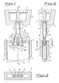
- a dip feed pipe or SEN 1 feeds by gravity with a molten metal or alloy 2, from an upper vessel or tundish 3 with a nearly constant head, a slab being formed within a thin slab mould 5 having cooling walls and comprising four vertical walls wherein two sides in horizontal section are longer than the other two. While shown in Fig 3 with a perfectly rectangular cross-section, the mould may have slightly convex or polygonal walls, or show a development slightly different from the perfectly vertical one shown in Fig. 2, without bringing about any changes in the features of the SEN according to the invention.
- the SEN comprises a length of vertical tube 6, not necessarily cylindrical with circular section, joined in a known manner to the upper vessel 3. It may be provided on the top with a flow control surface or regulation valve 7, whereas on the bottom it extends, through a connection zone 18, with a distributing flat portion, named later on as diffuser 8, having bottom outlet ports 9, 9'.
- the diffuser 8 allows to feed molten material under head 17 within the slab being formed 4 in the mould 5, while maintaining a certain distance from the walls thereof.
- the slab being formed 4 has been shown with solid walls having an increasing thickness from the top to the bottom, whereas the inner volume is to be regarded as still liquid or anyhow not yet fully hardened.
- a central flow divider 14 integral with both wider walls of the diffuser and adapted to divide the flow into two separate channels 16, 16' terminated at the bottom by two outlet ports 9, 9' discharging downwards.
- the cross-section 10 for the passage of the flow in the higher portion of diffuser 8, at the end of connection 18 with tube 6, has been represented preferably coincident with the top end of flow divider 14, as already in EP 0925132.
- the area of said cross-section 10 is narrower than the one relating to the passage section of upper tube 6 denoted by reference number 11.
- the ratio between these areas is in the range from 0,6 to 0,8. Such a condition is better visible in Fig. 2.
- Fig. 2 it is to be noted that even though the side walls of connection 18 in Fig. 1 do appear divergent downwards, namely in a cross-sectional view parallel to the wide faces of the mould, in all other sectional planes they are convergent, thus causing a reduction of cross-section area downwards.
- the reduction of the passage area between section 11 and section 10 is accomplished over a short piece with a length comprised between 4 and 6 times the hydraulic radius of pipe 6, the latter being equal to the ratio between the sectional area and the relevant wet periphery (for the circular sections, the hydraulic radius is equal to 1/4 of the diameter).
- the SEN according to the invention provides a length of firm acceleration of the flow of molten material between section 11 and upper section 10 of the diffuser as well as a further acceleration between section 10 and a narrow lower section 10bis in which takes place the maximum flow speed that afterwards gradually becomes slower along both channels 16 and 16' while maintaining the contact with the walls.
- Section 10bis is at a level below the upper vertex of flow divider 14 to avoid, thanks to the high flow rate and turbulence, a deposition of oxides just in the flow dividing zone, a deposition that would already occur in this zone in the presence of a premature slowing down of the stream.
- the passage section area of both flows 16 and 16' becomes even narrower between upper section 10 of the diffuser and 10bis of largest width of the flow divider. This can be achieved for instance by forming the above named upper zone of flow divider 14 with a suitable shape.
- the flow is slowed down in the twin diffusion channels 16 and 16' until having, at output holes 9, 9' a speed not exceeding 1,2 m/sec for any working condition.
- the output section of each channel 9, 9' in the mould is almost rectangular in shape with a so-called “aspect" ratio between the long side and short side at that cross-section comprised between 3 and 10.
- the said diffuser 8 towards the narrow sides of the mould 5, has inner side walls 12, 12' which symmetrically diverge and depart downwards from a vertical axis 13, with a curvature that is increasing in this embodiment from the top to the bottom and is a function of the maximum possible flow diffusion without vein detachment at the operation rates, with a shape resembling "a bell".
- the flow divider 14 narrows in its lower portion 15, 15', on the sides turned towards the narrow faces of the thin mould 5, thus forming two angles ⁇ with vertical axis 13, which in this case are ⁇ 8°.
- the function describing the upper contour of the flow divider has to be continuous and derivable without the presence of angular points according to the analytical definition (non-derivable points of the function as the first right and left derivatives do exist and are distinct).
- Fig. 4 shows the preferred embodiment of flow divider in which the geometry is of the ogival type, with an angle ⁇ at the apex of 45°, wherein the segment of line symmetrical with respect to the vertical plane II-II forming the intersection between the upper part of the flow divider with a vertical half-plane perpendicular to the plane comprising the axis of the continuous casting machine is a well connected sequence of circle arcs and straight segments, without discontinuities or angular points. Furthermore the radii of said circle arcs are increasing from the top downwards and the lowest arc is well connected towards the bottom without any discontinuity or angular points with the segment of one of the two converging straight lines 15, 15' according to said angle ⁇ .
- a throttle X formed as a disk provided with a circular gauged hole whose hydraulic radius with respect to the hydraulic radius of the tube corresponds to a ratio between 0,4 and 0,6, and whose thickness with respect to the diameter of the gauged hole corresponds to a ratio between 0,3 and 0,7.
- the submerged entry nozzle 1 instead of being provided with a flow controlling surface 7, as shown in Figs. 1 and 2, could be directly connected through a flange in a known manner with the bottom of container 3, whereas the flow controlling surface could be formed on a different element placed within the same container.
- the SEN 1 could also be secured through a flange, still in a known manner, below a flow regulating sliding gate and placed on the bottom of vessel 3, to operate in a known manner by selectively shutting the passage port formed between two perforated and opposed plates sliding over each other.
Landscapes
- Engineering & Computer Science (AREA)
- Mechanical Engineering (AREA)
- Continuous Casting (AREA)
Priority Applications (1)
| Application Number | Priority Date | Filing Date | Title |
|---|---|---|---|
| EP04425844A EP1657009A1 (fr) | 2004-11-12 | 2004-11-12 | Amélioration d'une buse de coulée immergée pour la coulée continue de l'acier |
Applications Claiming Priority (1)
| Application Number | Priority Date | Filing Date | Title |
|---|---|---|---|
| EP04425844A EP1657009A1 (fr) | 2004-11-12 | 2004-11-12 | Amélioration d'une buse de coulée immergée pour la coulée continue de l'acier |
Publications (1)
| Publication Number | Publication Date |
|---|---|
| EP1657009A1 true EP1657009A1 (fr) | 2006-05-17 |
Family
ID=34932883
Family Applications (1)
| Application Number | Title | Priority Date | Filing Date |
|---|---|---|---|
| EP04425844A Withdrawn EP1657009A1 (fr) | 2004-11-12 | 2004-11-12 | Amélioration d'une buse de coulée immergée pour la coulée continue de l'acier |
Country Status (1)
| Country | Link |
|---|---|
| EP (1) | EP1657009A1 (fr) |
Cited By (7)
| Publication number | Priority date | Publication date | Assignee | Title |
|---|---|---|---|---|
| EP1854571A1 (fr) * | 2006-05-11 | 2007-11-14 | ARVEDI, Giovanni | Buse de coulée à immersion pour coulée continu de l'acier |
| CN105838448A (zh) * | 2011-09-29 | 2016-08-10 | 通用电气公司 | 多流进料喷射器 |
| KR20170042551A (ko) * | 2014-06-11 | 2017-04-19 | 아르베디 스틸 엔지니어링 에스.피.에이. | 높은 질량 유량 분배를 위한 얇은 슬래브 노즐 |
| CN108025352A (zh) * | 2015-11-10 | 2018-05-11 | 黑崎播磨株式会社 | 浸渍喷嘴 |
| CN110340340A (zh) * | 2019-08-22 | 2019-10-18 | 中钢集团洛阳耐火材料研究院有限公司 | 一种ftsc薄板坯连铸浸入式水口用成型模具及成型方法 |
| CN110695349A (zh) * | 2019-11-21 | 2020-01-17 | 辽宁科技大学 | 一种csp薄板坯连铸高拉速浸入式水口及其制造方法 |
| CN113709006A (zh) * | 2021-10-29 | 2021-11-26 | 上海闪马智能科技有限公司 | 一种流量确定方法、装置、存储介质及电子装置 |
Citations (2)
| Publication number | Priority date | Publication date | Assignee | Title |
|---|---|---|---|---|
| WO2002000376A1 (fr) * | 2000-06-23 | 2002-01-03 | Vesuvius Crucible Company | Buse de moulage en continu a modulateur de pression |
| US6464154B1 (en) * | 1994-04-25 | 2002-10-15 | Versuvius Crucible Company | Casting nozzle with diamond-back internal geometry and multi-part casting nozzle with varying effective discharge angles and method for flowing liquid metal through same |
-
2004
- 2004-11-12 EP EP04425844A patent/EP1657009A1/fr not_active Withdrawn
Patent Citations (2)
| Publication number | Priority date | Publication date | Assignee | Title |
|---|---|---|---|---|
| US6464154B1 (en) * | 1994-04-25 | 2002-10-15 | Versuvius Crucible Company | Casting nozzle with diamond-back internal geometry and multi-part casting nozzle with varying effective discharge angles and method for flowing liquid metal through same |
| WO2002000376A1 (fr) * | 2000-06-23 | 2002-01-03 | Vesuvius Crucible Company | Buse de moulage en continu a modulateur de pression |
Cited By (12)
| Publication number | Priority date | Publication date | Assignee | Title |
|---|---|---|---|---|
| EP1854571A1 (fr) * | 2006-05-11 | 2007-11-14 | ARVEDI, Giovanni | Buse de coulée à immersion pour coulée continu de l'acier |
| CN105838448A (zh) * | 2011-09-29 | 2016-08-10 | 通用电气公司 | 多流进料喷射器 |
| KR20170042551A (ko) * | 2014-06-11 | 2017-04-19 | 아르베디 스틸 엔지니어링 에스.피.에이. | 높은 질량 유량 분배를 위한 얇은 슬래브 노즐 |
| JP2017526534A (ja) * | 2014-06-11 | 2017-09-14 | アルヴェーディ スティール エンジニアリング ソシエタ ペル アチオニ | 高質量流量を分布させるための薄スラブ用ノズル |
| US10569326B2 (en) | 2014-06-11 | 2020-02-25 | Arvedi Steel Engineering S.P.A. | Thin slab nozzle for distributing high mass flow rates |
| CN108025352A (zh) * | 2015-11-10 | 2018-05-11 | 黑崎播磨株式会社 | 浸渍喷嘴 |
| CN110340340A (zh) * | 2019-08-22 | 2019-10-18 | 中钢集团洛阳耐火材料研究院有限公司 | 一种ftsc薄板坯连铸浸入式水口用成型模具及成型方法 |
| CN110340340B (zh) * | 2019-08-22 | 2024-03-15 | 中钢集团洛阳耐火材料研究院有限公司 | 一种ftsc薄板坯连铸浸入式水口用成型模具及成型方法 |
| CN110695349A (zh) * | 2019-11-21 | 2020-01-17 | 辽宁科技大学 | 一种csp薄板坯连铸高拉速浸入式水口及其制造方法 |
| CN110695349B (zh) * | 2019-11-21 | 2024-03-12 | 辽宁科技大学 | 一种csp薄板坯连铸高拉速浸入式水口及其制造方法 |
| CN113709006A (zh) * | 2021-10-29 | 2021-11-26 | 上海闪马智能科技有限公司 | 一种流量确定方法、装置、存储介质及电子装置 |
| CN113709006B (zh) * | 2021-10-29 | 2022-02-08 | 上海闪马智能科技有限公司 | 一种流量确定方法、装置、存储介质及电子装置 |
Similar Documents
| Publication | Publication Date | Title |
|---|---|---|
| EP0925132B1 (fr) | Gicleurs immerges pour la coulee en continue de plaques fines | |
| JP3662973B2 (ja) | 連続鋳造用排出ノズル | |
| US3648761A (en) | Apparatus for distributing molten steel in a mold for a continuous casting | |
| RU2679664C2 (ru) | Стакан для литья тонких слябов для распределения расплавленного металла с высоким расходом | |
| EP1657009A1 (fr) | Amélioration d'une buse de coulée immergée pour la coulée continue de l'acier | |
| CN214161385U (zh) | 浇铸水口 | |
| JP3515762B2 (ja) | 連続鋳造用浸漬ノズル並びに連続鋳造方法 | |
| EP1854571B1 (fr) | Buse de coulée à immersion pour coulée continu de l'acier | |
| US6932250B2 (en) | Submerged entry nozzle and method for maintaining a quiet casting mold | |
| AU718124B2 (en) | Improved unit of equipments for the high-speed continuous casting of good quality thin steel slabs | |
| UA86601C2 (uk) | Заглибний розливальний стакан з багатьма випускними отворами (варіанти) | |
| KR100485404B1 (ko) | 박형슬라브를연속주조하기위한부분침수노즐 | |
| WO2020153195A1 (fr) | Buse immergée | |
| US5662862A (en) | Device for guiding molten steel in a tundish | |
| AU2002358590B2 (en) | Tundish and method for production of a metal strip of high purity | |
| RU2173608C2 (ru) | Погружной разливочный стакан для непрерывного литья тонких слябов | |
| US20210323055A1 (en) | Method of molten metal casting utilizing an impact pad in the tundish | |
| US20060118272A1 (en) | Method and apparatus for melt flow control in continuous casting mold |
Legal Events
| Date | Code | Title | Description |
|---|---|---|---|
| PUAI | Public reference made under article 153(3) epc to a published international application that has entered the european phase |
Free format text: ORIGINAL CODE: 0009012 |
|
| STAA | Information on the status of an ep patent application or granted ep patent |
Free format text: STATUS: THE APPLICATION HAS BEEN WITHDRAWN |
|
| AK | Designated contracting states |
Kind code of ref document: A1 Designated state(s): AT BE BG CH CY CZ DE DK EE ES FI FR GB GR HU IE IS IT LI LU MC NL PL PT RO SE SI SK TR |
|
| AX | Request for extension of the european patent |
Extension state: AL HR LT LV MK YU |
|
| 18W | Application withdrawn |
Effective date: 20060427 |