EP1657338A2 - Vorrichtung und Verfahren zum Auftragen einer verschäumten Zusammensetzung auf ein sich bewegendes nicht formbeständiges Substrat - Google Patents
Vorrichtung und Verfahren zum Auftragen einer verschäumten Zusammensetzung auf ein sich bewegendes nicht formbeständiges Substrat Download PDFInfo
- Publication number
- EP1657338A2 EP1657338A2 EP05024158A EP05024158A EP1657338A2 EP 1657338 A2 EP1657338 A2 EP 1657338A2 EP 05024158 A EP05024158 A EP 05024158A EP 05024158 A EP05024158 A EP 05024158A EP 1657338 A2 EP1657338 A2 EP 1657338A2
- Authority
- EP
- European Patent Office
- Prior art keywords
- substrate
- rollers
- roller
- pair
- applicator
- Prior art date
- Legal status (The legal status is an assumption and is not a legal conclusion. Google has not performed a legal analysis and makes no representation as to the accuracy of the status listed.)
- Granted
Links
Images


Classifications
-
- D—TEXTILES; PAPER
- D06—TREATMENT OF TEXTILES OR THE LIKE; LAUNDERING; FLEXIBLE MATERIALS NOT OTHERWISE PROVIDED FOR
- D06B—TREATING TEXTILE MATERIALS USING LIQUIDS, GASES OR VAPOURS
- D06B19/00—Treatment of textile materials by liquids, gases or vapours, not provided for in groups D06B1/00 - D06B17/00
- D06B19/0088—Treatment of textile materials by liquids, gases or vapours, not provided for in groups D06B1/00 - D06B17/00 using a short bath ratio liquor
- D06B19/0094—Treatment of textile materials by liquids, gases or vapours, not provided for in groups D06B1/00 - D06B17/00 using a short bath ratio liquor as a foam
-
- D—TEXTILES; PAPER
- D06—TREATMENT OF TEXTILES OR THE LIKE; LAUNDERING; FLEXIBLE MATERIALS NOT OTHERWISE PROVIDED FOR
- D06B—TREATING TEXTILE MATERIALS USING LIQUIDS, GASES OR VAPOURS
- D06B1/00—Applying liquids, gases or vapours onto textile materials to effect treatment, e.g. washing, dyeing, bleaching, sizing or impregnating
- D06B1/08—Applying liquids, gases or vapours onto textile materials to effect treatment, e.g. washing, dyeing, bleaching, sizing or impregnating from outlets being in, or almost in, contact with the textile material
Definitions
- the present invention relates to an apparatus and method for applying a foamed composition to a traveling substrate, and, more particularly, to a traveling substrate that has a tendency to be dimensionally unstable.
- the applicator applies the foam composition under pressure and at a location where the substrate is free or unsupported on the side of the substrate opposite the foam applicator.
- Substrates that are generally dimensionally stable such as woven textiles, can be treated in this manner.
- substrates that have a tendency to be dimensionally unstable such as knitted textiles, non-wovens, elastic fabric, and other somewhat uncontrollable substrates, have not been capable of having foamed compositions applied over an uncontrolled path of the substrate between supports because of the tendency of such substrates to contract widthwise and/or to have edges curl inwardly in the unsupported extent of the path of travel.
- the present invention provides an apparatus and method that is capable of effectively applying a foamed composition to substrates that normally have a tendency to be dimensionally unstable and to do this efficiently and effectively.
- the apparatus of the present invention includes a pair of closely spaced driven guide rollers over and between which the substrate is guided with sufficient roller engagement and controlled tension to minimize dimensional distortion.
- a foam applicator is provided with a substrate engaging foam dispensing nozzle face positioned within the space between the rollers of the pair of rollers to deflect the substrate inwardly between the rollers.
- the nozzle face extends in close proximity to the rollers to minimize the free extent of travel of the substrate between the rollers and the nozzle face.
- the controlled tension is obtained by means for driving the rollers at controlled relative rates of rotation.
- One of the guide rollers may be an input roller from which the substrate travels to the applicator nozzle face, and an infeed roller may be positioned closely adjacent the input roller, across which infeed roller the substrate travels onto the input roller, thereby minimizing the edge curling of the substrate.
- the infeed roller forms a nip with the input roller through which the substrate travels to the input roller.
- the apparatus applies a foamed composition to a traveling substrate that is flat with first and second opposite surfaces and there are two pairs of guide rollers with the substrate being guided with one surface in contact with one of the pairs of rollers and the other surface being in contact with the other surface of the substrate.
- One applicator applies foam to one surface of the substrate between the rollers of one pair of rollers and another applicator applies foam to the other surface of the substrate between the rollers of the other pair of rollers. All of the rollers provide sufficient roller engagement of the substrate and are driven with controlled tension to minimize dimensional distortion.
- the method of the present invention applies a foamed composition to a traveling substrate that has a tendency to be dimensionally unstable by arranging a pair of guide rollers in close proximity to each other, feeding the substrate for travel to and over a first roller of the pair and from the first roller to and over a second roller of the pair while maintaining sufficient roller engagement and controlled tension to minimize dimensional distortion.
- a foam applicator having a substrate engaging foam dispensing nozzle face is positioned with the face within the space between the rollers to deflect the substrate inwardly between the rollers, while positioning the nozzle face in close proximity to the rollers to minimize the free extent of travel of the substrate between the rollers and the nozzle face, thereby minimizing dimensional distortion of the substrate as it travels between the rollers and across the applicator nozzle face.
- the controlled tension may be obtained by the method of the present invention by driving the rollers at controlled relative rates of rotation, and disposing an infeed roller closely adjacent an input roller of the pair with the substrate being fed for travel between the infeed roller and the input roller and onto the input roller, thereby minimizing edge curling of the substrate.
- the infeed roller may be disposed to form a nip with the input roller and the substrate may be fed through the nip and onto the input roller.
- the substrate is a flat substrate with first and second opposite surfaces and is fed for traveling with one surface over the rollers of the first pair of rollers and the other surface traveling over the rollers of a second pair of rollers.
- the substrate In traveling over the first set of rollers, the substrate is fed with the opposite surface engaging a first applicator nozzle face between and closely adjacent the rollers of the first pair and the opposite surface is engaged by a nozzle face of a second applicator disposed between the rollers of the second pair.
- the method includes driving the rollers of both pairs at controlled relative rates of rotation to maintain tension and to minimize dimensional distortion in the substrate as it travels over the rollers, between the rollers and across the applicator nozzle faces.
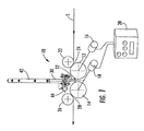
- Fig. 1 is a schematic illustration of one embodiment of the apparatus for applying a foamed composition according to the present invention, which illustrated embodiment is used in practicing the method of the present invention;
- Fig. 2 is a schematic illustration of another form of the apparatus of the present invention that can be used for practicing another form of the method of the present invention
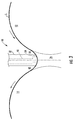
- Fig. 3 is an enlarged schematic illustration of the location of a foam applicator nozzle positioned between a pair of guide rollers according to the apparatus and method illustrated in Figs. 1 and 2;
- Fig. 4 is an illustration of another embodiment of the apparatus and method of the present invention, illustrating the components in position during foam application to a traveling substrate;
- Fig. 5 is an illustration of the components of Fig. 4 shown in a position in which the applicator nozzles may have a flushing fluid circulated therethrough;
- Fig. 6 is an illustration of the components of Fig. 4 shown in a position in which the applicator nozzles are disposed downwardly for draining fluid from the applicators.
- Fig. 1 illustrates an example of an apparatus 10 according to the present invention for use in applying a foamed composition to a traveling substrate S that has a tendency to be dimensionally unstable.
- the apparatus 10 includes a pair of guide rollers 12, 14. These rollers 12, 14 are arranged at a close spacing for travel of the substrate S over the input roller 12 of the pair and across the space between rollers onto, over and from the output roller 14 of the pair.
- a drive motor 16 is drivingly connected to the input roller 12 and a drive motor 18 is drivingly connected to the output roller 14.
- the motors 16 and 18 are controlled by a conventional controller 20 that is adjustable as desired to control the relative rates of rotation of the two guide rollers 12 and 14 and, therefore, the tension of the substrate S for optimum dimensional stability.
- An infeed roller 22 is disposed closely adjacent the input roller 12 for guiding the substrate S onto the input roller 12 to maintain the substrate S in sufficient contact with the guide roller 12, which, in combination with the surface of the guide rollers 12, 14 being rubber coated or treated or otherwise formed with a traction surface, results in the substrate S in engagement with the surface of the input roller 12 without significant slippage.
- the infeed roller 22 may be positioned to form a nip 24 with the input roller 12, thereby assuring that the edges of the substrate S do not curl as the substrate S travels onto the input roller 12.
- An outfeed roller 26 similar to the infeed roller 22, is positioned closely adjacent, and preferably forming a nip 28 with, the output roller 14. This outfeed roller 26 assures contact of the substrate S with the surface of the output roller 14, which is similarly covered or formed with a surface like that explained above with regard to the input roller 12, to assure travel of the substrate S with the surface of the output roller 14 without appreciable slippage.
- a foam applicator 30 is disposed with a substrate engaging foam dispensing nozzle 32 having a face 34 positioned within the space 36 between the input and output rollers 12, 14. This substrate engaging foam dispensing nozzle face 36 extends sufficiently into the space 36 to deflect the substrate inwardly between the rollers 12, 14 to maintain contact with the substrate S for optimal application of foam under pressure from the nozzle face 34.
- the applicator 30 is adjustable in any conventional manner to obtain optimal deflection of and tension in the substrate S for optimum application of foam thereto. This tension also retains the substrate S in substantial dimensional stability.
- nozzle face 36 extending in close proximity to the rollers 12 and 14, which minimizes the free extent of travel of the substrate between the rollers 12, 14 and nozzle face 34.
- Fig. 3 illustrates the substrate S traveling with and over the surface of the input roller 12 into the space between the rollers, into which it travels through the space 38 unsupported to the nozzle face 34, across the nozzle face 34, and then through the unsupported space 40 to the surface of the output roller 14.
- the nozzle face 34 is illustrated as having a curvature conforming somewhat to a smooth transition of the traveling substrate S from the input roller 12 across the face 34 and onto the output roller 14.
- the nozzle face 34 may be of any desired configuration and the nozzle face 32 may be of any compatible width. If a width narrower than that illustrated in Fig. 3 is the case, the input and output rollers 12 and 14 may be closer spaced or the nozzle face 32 may be further inserted into the space 36 to maintain sufficient closeness of the nozzle to the rollers for optimum minimization of any tendency of the substrate S to contract widthwise or edge curl in the spaces 38 and 40.
- the applicator 30 is shown having a foam distribution chamber 42 of a parabolic shape of the type disclosed in U.S. Patent No. 4,655,056, which causes a uniform distribution of generated foam entering through the inlet 44 throughout the foam distribution chamber 42 for uniform condition through the channel 48 of the nozzle 32 and out the nozzle face 34 as the foam is being applied to the traveling substrate S.
- the substrate S travels from a preceding operation in substantially flat widthwise extent to the infeed roller 22, which maintains it substantially flat and guides it into the nip 28 with the input roller 12.
- the input roller 12 carries the substrate on its surface as the roller rotates to the space 36, in which the substrate S travels to the applicator nozzle face 34 through the short space 38 between the input roller 12 and the nozzle face 34.
- the substrate S then passes across the nozzle face 34, which applies the foamed composition under pressure to the substrate S with the nozzle face 34 deflecting the substrate S in the space 36 to maintain tension on the substrate S, which is unsupported on the surface opposite the surface on which the nozzle face 34 is applying foam so that the foam under pressure will penetrate fully into the substrate S.
- the substrate S with the applied foam then travels from the nozzle face 34 through the short space 40 between the nozzle face 34 and the surface of the output roller 14, which then carries the substrate S on its surface to the nip 28 with the outfeed roller 26, from which the substrate S is discharged in substantially the same dimensional condition as it entered the apparatus. It then continues through further treatment, which may, for example, include a tenter frame for controlling the dimensional condition of the substrate S.
- the apparatus 10 of Fig. 1 is combined with a similar apparatus 50 arranged for applying foam to the opposite surface of the substrate S.
- a second pair of input and output rollers 52, 54 are arranged in sequence with the pair 12 and 14 of the apparatus 10, with the input roller 52 of this second pair being closely adjacent to the output roller 14 of the first pair for travel of the substrate S from the output roller 14 of the first pair.
- the first surface 56 of the substrate S that is in contact with the rollers 12 and 14 of the first pair, with the first applicator 30 applying foam to the opposite or second surface of the substrate S.
- the roller engagement is reversed on the apparatus 50 with the second surface 58 being engaged by and carried by the second pair of rollers 52, 54 with a second applicator 60 applying foam to the first surface 56 of the substrate S through the face 62 of the second nozzle 64.
- the second apparatus 50 is. identical to the first apparatus 10 except that it is arranged oppositely for applying foam to the opposite surface of the substrate S.
- the operation of the second apparatus 50 is identical to the operation of the first apparatus 10, except for the application of the foam to the opposite side of the substrate S.
- the second pair of input and output rollers 52, 54 are driven by motors 68 and 70 controlled by the aforementioned controller 20, which is adjustable for optimum control of the relative rotation of all four guide rollers, 12, 14, 52 and 54 to obtain optimal stabilization of the dimensions of the substrate S as it passes through the first and second apparatus 10 and 50.
- FIG. 4, 5 and 6 Another embodiment of the present invention is illustrated in Figs. 4, 5 and 6.
- the substrate S is fed in a generally vertical direction past vertically spaced and oppositely directed horizontally disposed applicators 130 and 160, with the nozzles 132 and 164 extending horizontally in contact with the opposite surfaces 156 and 158 of the substrate S.
- the substrate S is guided past the nozzles by two pairs of vertically spaced guide rollers.
- the first or upper pair of rollers, 112 and 114 are closely spaced in vertical alignment so that the nozzle 132 of the upper applicator 130 will be positioned in the space between the rollers, with the nozzle face 134 deflecting the substrate S and with the nozzle face 134 having its edges closely adjacent the upper rollers 112 and 114 to minimize possible dimensional distortion of the substrate S.
- This upper nozzle 132 applies the foamed composition to the first surface 156 of the substrate S.
- the second pair of guide rollers 152 and 154 is below and vertically aligned with the upper pair 112, 114, with the upper, or input roller 152 of the second pair of guide rollers being below and closely adjacent the output or lower roller 114 of the upper pair of guide rollers.
- the substrate S is guided with the first surface 156 in contact with the rollers 112, 114 of the first pair to the opposite or second surface 158 of the substrate S being in engagement with the guide rollers 152, 154 of the second pair of guide rollers.
- Each of the guide rollers 112, 114, 152 and 154 of the two pairs of guide rollers are independently driven at controlled rotational speeds through individual motors and a controller in the same manner as described above with regard to the embodiment of Fig. 2.
- an infeed roller 112 is mounted above and to the side opposite the first applicator 130.
- an outfeed roller 166 is disposed below the output roller 154 of the second pair of rollers and to the side of that roller opposite the second applicator nozzle 164 for guiding of the substrate S from the output roller 154 of the second pair of guide rollers around the outfeed roller 166 from which the substrate S travels away from the apparatus 100.
- the applicators, 130 and 160 are pivotable from the foamed composition applying positions illustrated in Fig. 4, in which position the applicator nozzles 132 and 164 are in horizontal dispositions as illustrated in Fig. 4, to a disposition in which the nozzles 132 and 164 are positioned vertically upward for flushing of the foamed composition from the applicators 130 and 160 as illustrated in Fig. 5, and to a draining position in which the nozzles 132 and 164 are positioned vertically downwardly.
- the pairs of guide rollers, 112, 114, 152 and 154 are mounted on pivotable brackets 102, 104.
- the upper pair of guide rollers 112, 114 and the infeed roller 122 are mounted on one bracket 102, which is an upper bracket.
- This upper bracket 102 is pivotally mounted on a rotatable shaft 106 that is pivotally secured to the frame 108 of the apparatus 100 above the upper pair of guide rollers 112, 114.
- This upper shaft 106 accommodates rotation of the upper bracket 102 in a conventional manner for pivoting the upper bracket and the guide rollers 112 and 114 and the infeed roller 122 mounted thereon sufficiently away from the upper applicator 130 to permit the aforementioned rotation of the applicator.
- the bracket 102 can be rotated reversely to reposition the upper bracket 102 and the guide rollers 112 and 114 of the upper pair of guide rollers and the infeed roller 122 for resumption of the application of the foamed composition to the substrate S from the upper applicator 130.
- the second or lower pair of rollers, 152 and 154 and the outfeed roller 166 are mounted on the lower bracket 104, which is mounted on a lower pivot shaft 109 disposed below the rollers for pivoting of the lower bracket 104 to move the lower or second pair of rollers 152, 154 away from the second applicator nozzle 164 to permit pivoting of the second applicator 160 into the flushing position of Fig. 5 where the nozzle 164 is pointed vertically into the draining position illustrated in Fig. 6, where the nozzle 164 is pointing downwardly.
- This bracket pivoting is accomplished by a conventional drive mechanism to pivot the lower bracket 104 toward and away from the second applicator nozzle 164.
- the foamed composition is flushed from the applicators 130 and 160 by forcing a flushing fluid through the applicators and out of the nozzle faces 134 and 162.
- the foamed composition and flushing fluid are discharged from the upwardly facing applicator nozzle faces 134 and 162, from which they flow downwardly over the exterior of the applicators 130 and 160 and across a triangularly shaped drain panel that tends to cause the flow along the triangular shape to the lower point 117, from which the material flows into a drain trough 119 that extends below the applicators.
- the applicators 130 and 160 are manipulated by pivoting to the position indicated in Fig. 6 where the nozzles 132 and 164 extend vertically downwardly above the troughs 119. In this position the flushing liquid that is in the applicators 130 and 160 drains from the applicators into the troughs 119.
- the foamed composition can be distributed to the applicator nozzles 132 and 164 in any desired manner.
- an incremental parabolic distributor such as that illustrated and disclosed in U.S. Patent No. 6,814,806 and indicated generally by the reference numeral 121 can be used to obtain equal pressure and flow of the foamed composition from the nozzle faces 134 and 162.
- the substrate S is threaded around the rollers when the rollers are in the position illustrated in Fig. 5. That is, the substrate S is wrapped around the infeed roller 122, over the input roller 112 of the upper pair of rollers, down around the output roller 54 of the lower pair of rollers, and around the outfeed roller 166.
- the brackets 102 and 104 are rotated toward the applicators to position the rollers and applicator nozzles in the positions illustrated in Fig. 4. In this position, the foamed composition is discharged from the nozzle faces 134 and 162 under pressure onto the adjacent surface of the substrate S.
- the applicators 130 and 160 are rotated on the shafts 111 and 113 to position the applicator nozzles 132 and 164 to extend vertically upwardly, as indicated in Fig. 5. In this position, flushing fluid is directed through the applicators 130 and 160 for flow out of the nozzle faces 134 and 162. When adequate flushing has been accomplished, flow of the flushing fluid is stopped and the flushing fluid remains in the applicators 130 and 160 to prevent any undesired drying of material in the applicators.
- the applicators 130 and 160 are rotated to the draining position illustrated in Fig. 6, wherein the nozzles 132 and 164 extend vertically downwardly to allow the material in the nozzles to drain into the drain troughs 119.
- the applicators 130 and 160 are then rotated into the applicating position in Fig. 4 and the brackets 102 and 104 are rotated into the applicating position illustrated in Fig. 4, with the nozzle faces 134 and 162 positioned in the spaces between the rollers in the manner illustrated in Fig. 3.
- the roller supporting brackets 102 and 104 are pivoted to move the rollers out of contact or interference with the applicator nozzles 132 and 164, the applicators 130 and 160 are rotated to the position illustrated in Fig. 5, with the nozzles 132 and 164 disposed vertically upwardly. Flushing fluid is then flowed through the applicators 130 and 160 until the foamed composition has been fully flushed. Flow of the flushing fluid is then discontinued with the flushing fluid remaining in the nozzles until the next application of the foamed composition to a substrate S, before which the applicators 130 and 160 are pivoted to the drain position illustrated in Fig.
Landscapes
- Engineering & Computer Science (AREA)
- Textile Engineering (AREA)
- Application Of Or Painting With Fluid Materials (AREA)
- Coating Apparatus (AREA)
Applications Claiming Priority (1)
| Application Number | Priority Date | Filing Date | Title |
|---|---|---|---|
| US10/987,073 US7431771B2 (en) | 2004-11-12 | 2004-11-12 | Apparatus and method for applying a foamed composition to a dimensionally unstable traveling substrate |
Publications (3)
| Publication Number | Publication Date |
|---|---|
| EP1657338A2 true EP1657338A2 (de) | 2006-05-17 |
| EP1657338A3 EP1657338A3 (de) | 2007-04-11 |
| EP1657338B1 EP1657338B1 (de) | 2012-04-11 |
Family
ID=35929595
Family Applications (1)
| Application Number | Title | Priority Date | Filing Date |
|---|---|---|---|
| EP05024158A Expired - Lifetime EP1657338B1 (de) | 2004-11-12 | 2005-11-05 | Vorrichtung und Verfahren zum Auftragen einer verschäumten Zusammensetzung auf ein sich bewegendes nicht formbeständiges Substrat |
Country Status (4)
| Country | Link |
|---|---|
| US (1) | US7431771B2 (de) |
| EP (1) | EP1657338B1 (de) |
| AT (1) | ATE553239T1 (de) |
| ES (1) | ES2383898T3 (de) |
Cited By (5)
| Publication number | Priority date | Publication date | Assignee | Title |
|---|---|---|---|---|
| WO2008147515A1 (en) | 2007-05-25 | 2008-12-04 | Gaston Systems, Inc. | Apparatus for dyeing textile substrates with foamed dye |
| GB2466067A (en) * | 2008-12-12 | 2010-06-16 | Autofoam Systems Ltd | Coating a fabric with a foam |
| DE102018120746A1 (de) * | 2018-08-24 | 2020-02-27 | Hansa Industrie-Mixer Gmbh & Co. Kg | Verfahren und Vorrichtung zum beidseitigen Imprägnieren einer Substratbahn mit einem Bindemittel |
| US11168423B2 (en) | 2018-03-12 | 2021-11-09 | Gaston Systems, Inc. | Dye fixing section for an indigo dyeing machine |
| US11179744B2 (en) | 2018-11-13 | 2021-11-23 | Gaston Systems, Inc. | Segmented distribution assembly for distributing fluid to an applicator nozzle |
Families Citing this family (3)
| Publication number | Priority date | Publication date | Assignee | Title |
|---|---|---|---|---|
| TWI358161B (en) * | 2007-07-24 | 2012-02-11 | Hon Hai Prec Ind Co Ltd | Electrical card connector |
| US8916012B2 (en) | 2010-12-28 | 2014-12-23 | Kimberly-Clark Worldwide, Inc. | Method of making substrates comprising frothed benefit agents |
| US10233296B2 (en) | 2013-05-30 | 2019-03-19 | Kimberly-Clark Worldwide, Inc. | Method of forming creped thin film-like structures from frothed chemistry |
Family Cites Families (105)
| Publication number | Priority date | Publication date | Assignee | Title |
|---|---|---|---|---|
| US2114618A (en) | 1935-04-29 | 1938-04-19 | Knute F Wallin | Process for coating fabrics |
| NL107191C (de) | 1957-12-24 | |||
| US2992627A (en) | 1958-10-13 | 1961-07-18 | Chapman Chem Co | Applicator |
| US3832427A (en) | 1968-10-14 | 1974-08-27 | Guthrie Ind Ltd | Process for continuously forming a polymeric resinous layer from a multicomponent liquid reactive mixture |
| US3722469A (en) | 1971-05-19 | 1973-03-27 | Int Paper Co | Foam header assembly |
| US3969780A (en) | 1972-05-04 | 1976-07-20 | Henderson James M | Continuous carpet dyeing process |
| US4064891A (en) | 1974-06-06 | 1977-12-27 | Hale Fire Pump Company | Plural fluid proportioning apparatus |
| US4016831A (en) | 1975-04-07 | 1977-04-12 | Burlington Industries, Inc. | Apparatus for applying a foam backing to fabric |
| US3993533A (en) | 1975-04-09 | 1976-11-23 | Carnegie-Mellon University | Method for making semiconductors for solar cells |
| ES448040A1 (es) | 1975-05-24 | 1977-07-01 | Hoechst Ag | Dispositivo para la aplicacion uniforme de banos liquidos detratamiento en forma de espuma sobre estructuras textiles planas. |
| US4089296A (en) | 1975-12-09 | 1978-05-16 | Congoleum Corporation | Apparatus for spreading foam material |
| US4023526A (en) | 1976-03-25 | 1977-05-17 | Union Carbide Corporation | Apparatus for application of foam to a substrate |
| US4062989A (en) | 1976-06-14 | 1977-12-13 | M. Lowenstein & Sons, Inc. | Method and apparatus for coating moving webs and products produced thereby |
| US4159355A (en) * | 1977-11-14 | 1979-06-26 | Scott Paper Company | Foam bonding |
| US4512279A (en) | 1977-12-22 | 1985-04-23 | Consolidated Papers, Inc. | Paper coating apparatus |
| US4299591A (en) | 1978-09-19 | 1981-11-10 | United Merchants And Manufacturers, Inc. | Textile printing process |
| US4237818A (en) | 1978-12-15 | 1980-12-09 | Gaston County Dyeing Machine Company | Means for applying treating liquor to textile substrate |
| US4239821A (en) | 1979-04-10 | 1980-12-16 | Dayco Corporation | Apparatus for and method of coating a wear layer of a carpeting strip with curable latex foam |
| US4225638A (en) | 1979-04-16 | 1980-09-30 | The D. L. Auld Company | Method and apparatus for flow coating with suck-back control |
| DE2939797A1 (de) | 1979-10-01 | 1981-04-16 | Fa. A. Monforts, 4050 Mönchengladbach | Verfahren zum kontinuierlichen beschaeumen eines textilen flaechengebildes und vorrichtung zum durchfuehren des verfahrens |
| DE2939767A1 (de) | 1979-10-01 | 1981-04-09 | Fa. A. Monforts, 4050 Mönchengladbach | Kontinuierliches verfahren zum gleichmaessigen schaumbehandeln von textilen flaechengebilden und vorrichtung zum durchfuehren des verfahrens |
| US4407767A (en) | 1979-10-31 | 1983-10-04 | Monsanto Company | Drawing and beaming a weftless warp of yarns |
| US4292918A (en) | 1980-01-08 | 1981-10-06 | West Point Pepperell, Inc. | Apparatus for applying liquid chemicals to a moving web |
| US4305169A (en) | 1980-01-09 | 1981-12-15 | Printaire Systems, Inc. | Method for continuously treating fabric |
| US4562097A (en) | 1980-05-09 | 1985-12-31 | Union Carbide Corporation | Process of treating fabrics with foam |
| DE3020668C2 (de) | 1980-05-30 | 1984-03-08 | Küsters, Eduard, 4150 Krefeld | Verfahren zum Behandeln einer Bahn mit Schaum |
| US4326904A (en) | 1980-06-02 | 1982-04-27 | National Starch And Chemical Corporation | Heat collapsing foam system |
| US4297860A (en) | 1980-07-23 | 1981-11-03 | West Point Pepperell, Inc. | Device for applying foam to textiles |
| DE3034804C2 (de) | 1980-09-16 | 1983-12-08 | Mathias 4815 Schloss Holte Mitter | Vorrichtung zum Auftragen eines Mediums auf eine Siebschablone, insbesondere zum Drucken oder Färben |
| US4442144A (en) | 1980-11-17 | 1984-04-10 | International Business Machines Corporation | Method for forming a coating on a substrate |
| US4646675A (en) | 1980-12-12 | 1987-03-03 | Molins Limited | Apparatus for applying fluid additive to fibrous material |
| US4343835A (en) | 1980-12-17 | 1982-08-10 | Union Carbide Corporation | Method and apparatus for treating open-weave substrates with foam |
| DE3265700D1 (en) | 1981-02-11 | 1985-10-03 | Ciba Geigy Ag | Process for dyeing or finishing fibrous textile materials |
| US4357373A (en) | 1981-04-15 | 1982-11-02 | Armstrong World Industries, Inc. | Apparatus for applying latex coating to moving fabric |
| US4394289A (en) | 1981-07-01 | 1983-07-19 | Brown Lamar W | Continuous foam generating system |
| DE3131545C2 (de) | 1981-08-08 | 1985-04-11 | Küsters, Eduard, 4150 Krefeld | Vorrichtung zum Auftragen von Schaum |
| AU548027B2 (en) | 1981-08-18 | 1985-11-21 | Kusters, Eduard | Applying patterns to webs |
| US4402200A (en) | 1981-09-04 | 1983-09-06 | Gaston County Dyeing Machine Company | Means for applying foamed treating liquor |
| US4641404A (en) | 1981-10-05 | 1987-02-10 | Seydel Scott O | Porous warp sizing apparatus |
| US4387118A (en) | 1981-10-29 | 1983-06-07 | Burlington Industries, Inc. | Minimizing voids in foam coating |
| JPS5879566A (ja) | 1981-11-04 | 1983-05-13 | Konishiroku Photo Ind Co Ltd | 塗布方法およびその装置 |
| US4431429A (en) | 1981-12-24 | 1984-02-14 | Rbi International Carpet Consultants | Carpet dyeing system |
| US4637940A (en) | 1982-02-22 | 1987-01-20 | Dayco Corporation | Elastomer-coated bias reinforcement fabric and method for producing same |
| US4501771A (en) | 1982-02-22 | 1985-02-26 | Dayco Corporation | Elastomer-coated bias reinforcement fabric and method for producing same |
| US4753823A (en) | 1982-02-22 | 1988-06-28 | Dayco Products, Inc. | Method for producing elastomer-coated bias fabric |
| US4970039A (en) | 1982-02-22 | 1990-11-13 | Dayco Products, Inc. | Elastomer-coated bias reinforcement fabric and method for making same |
| US4769260A (en) | 1982-02-22 | 1988-09-06 | Dayco Products, Inc. | Elastomer-coated bias reinforcement fabric and method for producing same |
| US4711792A (en) | 1982-02-22 | 1987-12-08 | Dayco Products, Inc. | Elastomer-coated bias reinforcement fabric and method for producing same |
| US4565715A (en) | 1982-02-22 | 1986-01-21 | Dayco Corporation | Elastomer-coated bias reinforcement fabric and method for producing same |
| US4622243A (en) | 1982-02-22 | 1986-11-11 | Dayco Corporation | Method and apparatus for producing elastomer-coated bias fabric |
| US4624813A (en) | 1982-02-22 | 1986-11-25 | Dayco Corporation | Elastomer-coated bias reinforcement fabric and method and apparatus for producing same |
| US4420510A (en) | 1982-03-23 | 1983-12-13 | Weyerhaeuser Company | Method for applying a foamed adhesive under start-stop conditions |
| US5145527A (en) | 1982-04-09 | 1992-09-08 | Owens-Corning Fiberglas Corporation | Apparatus for applying foamed treating liquor |
| US5008131A (en) | 1982-06-14 | 1991-04-16 | Owens-Corning Fiberglas Corporation | Method and apparatus for impregnating a porous substrate with foam |
| US5009932A (en) | 1982-06-14 | 1991-04-23 | Owens-Corning Fiberglas Corporation | Method and apparatus for impregnating a porous substrate with foam |
| US4398665A (en) | 1982-06-18 | 1983-08-16 | West Point Pepperell, Inc. | Apparatus for uniformly applying either liquid or foam compositions to a moving web |
| US4485508A (en) | 1982-06-23 | 1984-12-04 | Otting International, Inc. | Method and apparatus for dyeing of textile material |
| US4773110A (en) | 1982-09-13 | 1988-09-27 | Dexter Chemical Corporation | Foam finishing apparatus and method |
| US4500039A (en) | 1982-10-20 | 1985-02-19 | West Point Pepperell, Inc. | Apparatus for uniformly applying either liquid or foam compositions to a moving web |
| US4661399A (en) | 1983-04-05 | 1987-04-28 | Dayco Products, Inc. | Polymeric-coated fabric layer, product utilizing the layer and method of making the same |
| US4528214A (en) | 1983-04-20 | 1985-07-09 | Dayco Corporation | Polymeric product having a fabric layer means and method of making the same |
| US4521362A (en) | 1983-04-29 | 1985-06-04 | Dayco Corporation | Method and apparatus for making a polymeric coated layer |
| US4473521A (en) | 1983-04-29 | 1984-09-25 | Dayco Corporation | Method and apparatus for making a polymeric coated fabric layer |
| US4582660A (en) | 1983-04-29 | 1986-04-15 | Dayco Corporation | Method and apparatus for making a polymeric coated fabric layer |
| DE3315770A1 (de) | 1983-04-30 | 1984-10-31 | Küsters, Eduard, 4150 Krefeld | Vorrichtung zum auftragen eines behandlungsmittels, insbesondere in schaumform, auf eine laufende warenbahn |
| DE3318711C2 (de) | 1983-05-21 | 1986-01-23 | Hansa Industrie-Mixer GmbH & Co KG, 2800 Bremen | Vorrichtung zum kontinuierlichen Herstellen und Auftragen von Schaum auf ein zu beschichtendes flächiges Gebilde |
| US4548611A (en) | 1983-05-31 | 1985-10-22 | Paterson James G T | Method and apparatus for dyeing textile yarn substrates by impacting a foam |
| US4502304A (en) | 1984-05-01 | 1985-03-05 | Dexter Chemical Corporation | Foam applicator for wide fabrics |
| US4569107A (en) | 1984-08-08 | 1986-02-11 | Texfi Industries, Inc. | Method of forming a warp beam for a textile loom |
| US4741924A (en) | 1984-11-29 | 1988-05-03 | Dayco Products, Inc. | Method of making a polymeric coated fabric layer |
| US4792252A (en) | 1985-02-27 | 1988-12-20 | Pittway Corporation | Liquid applicator device |
| US4581254A (en) | 1985-03-22 | 1986-04-08 | Union Carbide Corporation | Foam applicator used in paper treatment |
| US4644900A (en) | 1985-04-25 | 1987-02-24 | Poterala Robert J | Coating apparatus with automatic trough control and seam passage |
| AT386762B (de) | 1985-05-08 | 1988-10-10 | Zimmer Johannes | Verfahren und vorrichtung zum impraegnierenden und/oder beschichtenden auftragen auf eine warenbahn |
| US4655056A (en) | 1985-06-11 | 1987-04-07 | Gaston County Dyeing Machine Co. | Foamed treating liquor applicator |
| US4656063A (en) | 1985-08-27 | 1987-04-07 | Long Harry F | Curtain coating method |
| US4624213A (en) | 1985-08-27 | 1986-11-25 | Armstrong World Industries, Inc. | Curtain coating apparatus and method of use |
| US4844001A (en) | 1987-12-30 | 1989-07-04 | Mcneil Lab, Inc. | Removable and rotatable coating pan spray arm assembly |
| US4796558A (en) | 1988-02-19 | 1989-01-10 | Electrovert Limited | Foam fluxer |
| US5089296A (en) | 1988-04-08 | 1992-02-18 | Air Products And Chemicals, Inc. | Foam saturation and release coating of a fibrous substrate |
| KR910002287B1 (ko) | 1988-06-20 | 1991-04-11 | 쯔다고마 고오교오 가부시끼가이샤 | 호부기(湖付機)의 호점도(湖粘度) 제어방법 및 장치 |
| US5074883A (en) | 1989-12-11 | 1991-12-24 | Minnesota Mining And Manufacturing Company | Process for providing polyamide materials with stain resistance |
| KR920000782Y1 (ko) | 1990-03-05 | 1992-01-31 | 동양섬유산업 주식회사 | 다댁상기포염색가공기의 제트 애프리케이터(Jet Applicator) |
| DE4015946C3 (de) | 1990-05-18 | 1996-06-20 | Kuesters Eduard Maschf | Ablaufplatte für eine Vorrichtung zum Aufbringen eines Flüssigkeitsfilms auf eine Warenbahn |
| US5202077A (en) | 1990-07-10 | 1993-04-13 | Milliken Research Corporation | Method for removal of substrate material by means of heated pressurized fluid stream |
| US5066428A (en) | 1990-08-08 | 1991-11-19 | Rusmar Incorporated | Foam generating apparatus |
| DE4202720A1 (de) | 1991-05-02 | 1992-11-05 | Henkel Kgaa | Verbesserung beim spruehauftrag waessriger behandlungsflotten auf textilmaterial |
| US5219620A (en) | 1991-07-25 | 1993-06-15 | E. I. Du Pont De Nemours And Company | Method and apparatus for foam treating pile fabrics |
| US5403622A (en) | 1992-07-07 | 1995-04-04 | Konica Corporation | Method for feeding a coating solution |
| DE69314343T2 (de) | 1992-07-08 | 1998-03-26 | Nordson Corp | Vorrichtung und verfahren zum aufbringen von schaumbeschichtungen |
| US5418009A (en) | 1992-07-08 | 1995-05-23 | Nordson Corporation | Apparatus and methods for intermittently applying discrete adhesive coatings |
| CA2098784A1 (en) | 1992-07-08 | 1994-01-09 | Bentley Boger | Apparatus and methods for applying conformal coatings to electronic circuit boards |
| US5326402A (en) | 1992-12-31 | 1994-07-05 | E. I. Du Pont De Nemours And Company | Slide-bead coating technique |
| US5367982A (en) | 1993-02-25 | 1994-11-29 | Howard W. DeMoore | Automatic coating circulation and wash-up system for printing presses |
| US5556471A (en) | 1994-05-17 | 1996-09-17 | Nordson Corporation | Method and apparatus for dispensing foam materials |
| US5657520A (en) | 1995-01-26 | 1997-08-19 | International Paper Company | Method for tentering hydroenhanced fabric |
| US5505995A (en) | 1995-02-02 | 1996-04-09 | Minnesota Mining And Manufacturing Company | Method and apparatus for coating substrates using an air knife |
| US5683508A (en) | 1995-08-25 | 1997-11-04 | Fit Group, Inc. | Coating apparatus and method for dispensing a liquid, and draining and cleaning a coating apparatus |
| US5642548A (en) | 1996-02-20 | 1997-07-01 | Gaston County Dyeing Machine Company | Apparatus and method for wet processing traveling textile material |
| US5891812A (en) | 1996-10-11 | 1999-04-06 | Isolyser Company, Inc. | Liquid absorbable non-permeable fabrics and methods of making, using, and disposing thereof |
| US5887519A (en) | 1997-09-29 | 1999-03-30 | Zelko; Steve | Screen printing machines |
| US6042573A (en) * | 1997-12-11 | 2000-03-28 | Smith & Nephew, Inc. | Surgical valve |
| US6432202B1 (en) | 1998-10-20 | 2002-08-13 | Gaston Systems, Inc. | Textile yarn slashing system |
| US6395088B1 (en) | 1999-06-30 | 2002-05-28 | Gaston Systems, Inc. | Apparatus for applying foamed coating material to a traveling textile substrate |
| US6814806B2 (en) | 2002-07-25 | 2004-11-09 | Gaston Systems Inc. | Controlled flow applicator |
-
2004
- 2004-11-12 US US10/987,073 patent/US7431771B2/en not_active Expired - Lifetime
-
2005
- 2005-11-05 AT AT05024158T patent/ATE553239T1/de active
- 2005-11-05 EP EP05024158A patent/EP1657338B1/de not_active Expired - Lifetime
- 2005-11-05 ES ES05024158T patent/ES2383898T3/es not_active Expired - Lifetime
Non-Patent Citations (1)
| Title |
|---|
| None |
Cited By (10)
| Publication number | Priority date | Publication date | Assignee | Title |
|---|---|---|---|---|
| US7913524B2 (en) | 2004-04-28 | 2011-03-29 | Gaston Systems, Inc. | Apparatus for dyeing textile substrates with foamed dye |
| WO2008147515A1 (en) | 2007-05-25 | 2008-12-04 | Gaston Systems, Inc. | Apparatus for dyeing textile substrates with foamed dye |
| EP2150648A4 (de) * | 2007-05-25 | 2010-11-03 | Gaston Systems Inc | Vorrichtung zur färbung von textilsubstraten mit geschäumtem farbstoff |
| CN101883888B (zh) * | 2007-05-25 | 2012-07-18 | 加斯顿系统公司 | 用泡沫染料对纺织品基材进行染色的设备 |
| EP2286021A4 (de) * | 2008-01-31 | 2011-06-15 | Gaston Systems Inc | Vorrichtung zum färben von textilen flächengebilden und garnen mit farbschaum |
| GB2466067A (en) * | 2008-12-12 | 2010-06-16 | Autofoam Systems Ltd | Coating a fabric with a foam |
| US11168423B2 (en) | 2018-03-12 | 2021-11-09 | Gaston Systems, Inc. | Dye fixing section for an indigo dyeing machine |
| DE102018120746A1 (de) * | 2018-08-24 | 2020-02-27 | Hansa Industrie-Mixer Gmbh & Co. Kg | Verfahren und Vorrichtung zum beidseitigen Imprägnieren einer Substratbahn mit einem Bindemittel |
| DE102018120746B4 (de) | 2018-08-24 | 2023-01-26 | Hansa Industrie-Mixer Gmbh & Co. Kg | Verfahren und Vorrichtung zum beidseitigen Imprägnieren einer Substratbahn mit einem Bindemittel |
| US11179744B2 (en) | 2018-11-13 | 2021-11-23 | Gaston Systems, Inc. | Segmented distribution assembly for distributing fluid to an applicator nozzle |
Also Published As
| Publication number | Publication date |
|---|---|
| EP1657338A3 (de) | 2007-04-11 |
| US7431771B2 (en) | 2008-10-07 |
| ATE553239T1 (de) | 2012-04-15 |
| EP1657338B1 (de) | 2012-04-11 |
| HK1091876A1 (en) | 2007-01-26 |
| ES2383898T3 (es) | 2012-06-27 |
| US20060102071A1 (en) | 2006-05-18 |
Similar Documents
| Publication | Publication Date | Title |
|---|---|---|
| US7431771B2 (en) | Apparatus and method for applying a foamed composition to a dimensionally unstable traveling substrate | |
| US4497273A (en) | Apparatus for uniform application of liquid treating media to workpiece webs | |
| EP0022333B1 (de) | Auftragen von Flüssigkeiten auf Textilgut | |
| US3997928A (en) | Method for the treatment of textile, fleece and similar webs | |
| US6858256B2 (en) | Apparatus for applying foamed coating material to a traveling textile substrate | |
| US5795391A (en) | Method and apparatus for application of fluent material to a moving substrate | |
| US6432202B1 (en) | Textile yarn slashing system | |
| CA1228740A (en) | Apparatus and method for pad batch dyeing of tubular knitted cotton fabrics | |
| US4455845A (en) | Apparatus for forming patterns in materials such as textile goods | |
| JPS5969179A (ja) | 発泡液の塗布方法 | |
| HK1091876B (en) | Apparatus and method for applying a foamed composition to a dimensionally unstable traveling substrate | |
| US2067915A (en) | Apparatus for the continuous treatment of textile fabrics with liquids | |
| AU2003203342B2 (en) | Treatment apparatus for chemical modification of animal fibers of continuous web form | |
| US4335593A (en) | Chainless mercerizing equipment using a dye padder | |
| US4282729A (en) | Foam random dyeing system | |
| US4674437A (en) | Size applicator | |
| US10704174B2 (en) | Device for applying a foamed treating material under pressure to a traveling sheet of textile yarn | |
| US4587813A (en) | Apparatus for applying treatment material to a textile material | |
| US6206979B1 (en) | Process and apparatus for treating a strip material in a liquid bath | |
| CN115672662B (zh) | 一种用于纺织纤维的表面上处理剂装置及方法 | |
| US4388740A (en) | Foam random dyeing system | |
| EP4394101B1 (de) | Vorrichtung zum schlichten von kettfäden | |
| CN216427633U (zh) | 一种双面涂覆上液装置 | |
| JPH07103509B2 (ja) | 生地の処理装置 | |
| JPS5925906Y2 (ja) | 生地の精練用滞溜装置 |
Legal Events
| Date | Code | Title | Description |
|---|---|---|---|
| PUAI | Public reference made under article 153(3) epc to a published international application that has entered the european phase |
Free format text: ORIGINAL CODE: 0009012 |
|
| AK | Designated contracting states |
Kind code of ref document: A2 Designated state(s): AT BE BG CH CY CZ DE DK EE ES FI FR GB GR HU IE IS IT LI LT LU LV MC NL PL PT RO SE SI SK TR |
|
| AX | Request for extension of the european patent |
Extension state: AL BA HR MK YU |
|
| REG | Reference to a national code |
Ref country code: HK Ref legal event code: DE Ref document number: 1091876 Country of ref document: HK |
|
| PUAL | Search report despatched |
Free format text: ORIGINAL CODE: 0009013 |
|
| AK | Designated contracting states |
Kind code of ref document: A3 Designated state(s): AT BE BG CH CY CZ DE DK EE ES FI FR GB GR HU IE IS IT LI LT LU LV MC NL PL PT RO SE SI SK TR |
|
| AX | Request for extension of the european patent |
Extension state: AL BA HR MK YU |
|
| 17P | Request for examination filed |
Effective date: 20070620 |
|
| AKX | Designation fees paid |
Designated state(s): AT BE BG CH CY CZ DE DK EE ES FI FR GB GR HU IE IS IT LI LT LU LV MC NL PL PT RO SE SI SK TR |
|
| 17Q | First examination report despatched |
Effective date: 20100301 |
|
| GRAP | Despatch of communication of intention to grant a patent |
Free format text: ORIGINAL CODE: EPIDOSNIGR1 |
|
| GRAS | Grant fee paid |
Free format text: ORIGINAL CODE: EPIDOSNIGR3 |
|
| GRAA | (expected) grant |
Free format text: ORIGINAL CODE: 0009210 |
|
| AK | Designated contracting states |
Kind code of ref document: B1 Designated state(s): AT BE BG CH CY CZ DE DK EE ES FI FR GB GR HU IE IS IT LI LT LU LV MC NL PL PT RO SE SI SK TR |
|
| REG | Reference to a national code |
Ref country code: GB Ref legal event code: FG4D |
|
| REG | Reference to a national code |
Ref country code: CH Ref legal event code: EP |
|
| REG | Reference to a national code |
Ref country code: AT Ref legal event code: REF Ref document number: 553239 Country of ref document: AT Kind code of ref document: T Effective date: 20120415 |
|
| REG | Reference to a national code |
Ref country code: IE Ref legal event code: FG4D |
|
| REG | Reference to a national code |
Ref country code: DE Ref legal event code: R096 Ref document number: 602005033558 Country of ref document: DE Effective date: 20120606 |
|
| REG | Reference to a national code |
Ref country code: CH Ref legal event code: NV Representative=s name: ZIMMERLI, WAGNER & PARTNER AG |
|
| REG | Reference to a national code |
Ref country code: ES Ref legal event code: FG2A Ref document number: 2383898 Country of ref document: ES Kind code of ref document: T3 Effective date: 20120627 |
|
| REG | Reference to a national code |
Ref country code: NL Ref legal event code: VDEP Effective date: 20120411 |
|
| REG | Reference to a national code |
Ref country code: AT Ref legal event code: MK05 Ref document number: 553239 Country of ref document: AT Kind code of ref document: T Effective date: 20120411 |
|
| LTIE | Lt: invalidation of european patent or patent extension |
Effective date: 20120411 |
|
| PG25 | Lapsed in a contracting state [announced via postgrant information from national office to epo] |
Ref country code: IS Free format text: LAPSE BECAUSE OF FAILURE TO SUBMIT A TRANSLATION OF THE DESCRIPTION OR TO PAY THE FEE WITHIN THE PRESCRIBED TIME-LIMIT Effective date: 20120811 Ref country code: LT Free format text: LAPSE BECAUSE OF FAILURE TO SUBMIT A TRANSLATION OF THE DESCRIPTION OR TO PAY THE FEE WITHIN THE PRESCRIBED TIME-LIMIT Effective date: 20120411 Ref country code: CY Free format text: LAPSE BECAUSE OF FAILURE TO SUBMIT A TRANSLATION OF THE DESCRIPTION OR TO PAY THE FEE WITHIN THE PRESCRIBED TIME-LIMIT Effective date: 20120411 Ref country code: FI Free format text: LAPSE BECAUSE OF FAILURE TO SUBMIT A TRANSLATION OF THE DESCRIPTION OR TO PAY THE FEE WITHIN THE PRESCRIBED TIME-LIMIT Effective date: 20120411 Ref country code: PL Free format text: LAPSE BECAUSE OF FAILURE TO SUBMIT A TRANSLATION OF THE DESCRIPTION OR TO PAY THE FEE WITHIN THE PRESCRIBED TIME-LIMIT Effective date: 20120411 Ref country code: SE Free format text: LAPSE BECAUSE OF FAILURE TO SUBMIT A TRANSLATION OF THE DESCRIPTION OR TO PAY THE FEE WITHIN THE PRESCRIBED TIME-LIMIT Effective date: 20120411 |
|
| PG25 | Lapsed in a contracting state [announced via postgrant information from national office to epo] |
Ref country code: GR Free format text: LAPSE BECAUSE OF FAILURE TO SUBMIT A TRANSLATION OF THE DESCRIPTION OR TO PAY THE FEE WITHIN THE PRESCRIBED TIME-LIMIT Effective date: 20120712 Ref country code: LV Free format text: LAPSE BECAUSE OF FAILURE TO SUBMIT A TRANSLATION OF THE DESCRIPTION OR TO PAY THE FEE WITHIN THE PRESCRIBED TIME-LIMIT Effective date: 20120411 Ref country code: PT Free format text: LAPSE BECAUSE OF FAILURE TO SUBMIT A TRANSLATION OF THE DESCRIPTION OR TO PAY THE FEE WITHIN THE PRESCRIBED TIME-LIMIT Effective date: 20120813 Ref country code: SI Free format text: LAPSE BECAUSE OF FAILURE TO SUBMIT A TRANSLATION OF THE DESCRIPTION OR TO PAY THE FEE WITHIN THE PRESCRIBED TIME-LIMIT Effective date: 20120411 |
|
| PG25 | Lapsed in a contracting state [announced via postgrant information from national office to epo] |
Ref country code: BE Free format text: LAPSE BECAUSE OF FAILURE TO SUBMIT A TRANSLATION OF THE DESCRIPTION OR TO PAY THE FEE WITHIN THE PRESCRIBED TIME-LIMIT Effective date: 20120411 |
|
| REG | Reference to a national code |
Ref country code: HK Ref legal event code: GR Ref document number: 1091876 Country of ref document: HK |
|
| PG25 | Lapsed in a contracting state [announced via postgrant information from national office to epo] |
Ref country code: CZ Free format text: LAPSE BECAUSE OF FAILURE TO SUBMIT A TRANSLATION OF THE DESCRIPTION OR TO PAY THE FEE WITHIN THE PRESCRIBED TIME-LIMIT Effective date: 20120411 Ref country code: AT Free format text: LAPSE BECAUSE OF FAILURE TO SUBMIT A TRANSLATION OF THE DESCRIPTION OR TO PAY THE FEE WITHIN THE PRESCRIBED TIME-LIMIT Effective date: 20120411 Ref country code: NL Free format text: LAPSE BECAUSE OF FAILURE TO SUBMIT A TRANSLATION OF THE DESCRIPTION OR TO PAY THE FEE WITHIN THE PRESCRIBED TIME-LIMIT Effective date: 20120411 Ref country code: DK Free format text: LAPSE BECAUSE OF FAILURE TO SUBMIT A TRANSLATION OF THE DESCRIPTION OR TO PAY THE FEE WITHIN THE PRESCRIBED TIME-LIMIT Effective date: 20120411 Ref country code: EE Free format text: LAPSE BECAUSE OF FAILURE TO SUBMIT A TRANSLATION OF THE DESCRIPTION OR TO PAY THE FEE WITHIN THE PRESCRIBED TIME-LIMIT Effective date: 20120411 Ref country code: SK Free format text: LAPSE BECAUSE OF FAILURE TO SUBMIT A TRANSLATION OF THE DESCRIPTION OR TO PAY THE FEE WITHIN THE PRESCRIBED TIME-LIMIT Effective date: 20120411 Ref country code: RO Free format text: LAPSE BECAUSE OF FAILURE TO SUBMIT A TRANSLATION OF THE DESCRIPTION OR TO PAY THE FEE WITHIN THE PRESCRIBED TIME-LIMIT Effective date: 20120411 |
|
| PLBE | No opposition filed within time limit |
Free format text: ORIGINAL CODE: 0009261 |
|
| STAA | Information on the status of an ep patent application or granted ep patent |
Free format text: STATUS: NO OPPOSITION FILED WITHIN TIME LIMIT |
|
| 26N | No opposition filed |
Effective date: 20130114 |
|
| REG | Reference to a national code |
Ref country code: DE Ref legal event code: R097 Ref document number: 602005033558 Country of ref document: DE Effective date: 20130114 |
|
| PG25 | Lapsed in a contracting state [announced via postgrant information from national office to epo] |
Ref country code: BG Free format text: LAPSE BECAUSE OF FAILURE TO SUBMIT A TRANSLATION OF THE DESCRIPTION OR TO PAY THE FEE WITHIN THE PRESCRIBED TIME-LIMIT Effective date: 20120711 |
|
| REG | Reference to a national code |
Ref country code: IE Ref legal event code: MM4A |
|
| PG25 | Lapsed in a contracting state [announced via postgrant information from national office to epo] |
Ref country code: IE Free format text: LAPSE BECAUSE OF NON-PAYMENT OF DUE FEES Effective date: 20121105 |
|
| REG | Reference to a national code |
Ref country code: CH Ref legal event code: NV Representative=s name: WAGNER PATENT AG, CH |
|
| PG25 | Lapsed in a contracting state [announced via postgrant information from national office to epo] |
Ref country code: MC Free format text: LAPSE BECAUSE OF NON-PAYMENT OF DUE FEES Effective date: 20121130 |
|
| PG25 | Lapsed in a contracting state [announced via postgrant information from national office to epo] |
Ref country code: LU Free format text: LAPSE BECAUSE OF NON-PAYMENT OF DUE FEES Effective date: 20121105 |
|
| PG25 | Lapsed in a contracting state [announced via postgrant information from national office to epo] |
Ref country code: HU Free format text: LAPSE BECAUSE OF FAILURE TO SUBMIT A TRANSLATION OF THE DESCRIPTION OR TO PAY THE FEE WITHIN THE PRESCRIBED TIME-LIMIT Effective date: 20051105 |
|
| REG | Reference to a national code |
Ref country code: FR Ref legal event code: PLFP Year of fee payment: 11 |
|
| REG | Reference to a national code |
Ref country code: FR Ref legal event code: PLFP Year of fee payment: 12 |
|
| REG | Reference to a national code |
Ref country code: FR Ref legal event code: PLFP Year of fee payment: 13 |
|
| PGFP | Annual fee paid to national office [announced via postgrant information from national office to epo] |
Ref country code: DE Payment date: 20191121 Year of fee payment: 15 |
|
| PGFP | Annual fee paid to national office [announced via postgrant information from national office to epo] |
Ref country code: FR Payment date: 20191121 Year of fee payment: 15 |
|
| PGFP | Annual fee paid to national office [announced via postgrant information from national office to epo] |
Ref country code: GB Payment date: 20191126 Year of fee payment: 15 |
|
| PGFP | Annual fee paid to national office [announced via postgrant information from national office to epo] |
Ref country code: CH Payment date: 20201130 Year of fee payment: 16 |
|
| REG | Reference to a national code |
Ref country code: DE Ref legal event code: R119 Ref document number: 602005033558 Country of ref document: DE |
|
| GBPC | Gb: european patent ceased through non-payment of renewal fee |
Effective date: 20201105 |
|
| PG25 | Lapsed in a contracting state [announced via postgrant information from national office to epo] |
Ref country code: FR Free format text: LAPSE BECAUSE OF NON-PAYMENT OF DUE FEES Effective date: 20201130 |
|
| PG25 | Lapsed in a contracting state [announced via postgrant information from national office to epo] |
Ref country code: DE Free format text: LAPSE BECAUSE OF NON-PAYMENT OF DUE FEES Effective date: 20210601 Ref country code: GB Free format text: LAPSE BECAUSE OF NON-PAYMENT OF DUE FEES Effective date: 20201105 |
|
| REG | Reference to a national code |
Ref country code: CH Ref legal event code: PL |
|
| PG25 | Lapsed in a contracting state [announced via postgrant information from national office to epo] |
Ref country code: LI Free format text: LAPSE BECAUSE OF NON-PAYMENT OF DUE FEES Effective date: 20211130 Ref country code: CH Free format text: LAPSE BECAUSE OF NON-PAYMENT OF DUE FEES Effective date: 20211130 |
|
| PGFP | Annual fee paid to national office [announced via postgrant information from national office to epo] |
Ref country code: ES Payment date: 20221216 Year of fee payment: 18 |
|
| PGFP | Annual fee paid to national office [announced via postgrant information from national office to epo] |
Ref country code: TR Payment date: 20231127 Year of fee payment: 19 Ref country code: IT Payment date: 20231130 Year of fee payment: 19 |
|
| REG | Reference to a national code |
Ref country code: ES Ref legal event code: FD2A Effective date: 20250102 |
|
| PG25 | Lapsed in a contracting state [announced via postgrant information from national office to epo] |
Ref country code: ES Free format text: LAPSE BECAUSE OF NON-PAYMENT OF DUE FEES Effective date: 20231106 |
|
| PG25 | Lapsed in a contracting state [announced via postgrant information from national office to epo] |
Ref country code: ES Free format text: LAPSE BECAUSE OF NON-PAYMENT OF DUE FEES Effective date: 20231106 |
|
| PG25 | Lapsed in a contracting state [announced via postgrant information from national office to epo] |
Ref country code: IT Free format text: LAPSE BECAUSE OF NON-PAYMENT OF DUE FEES Effective date: 20241105 |