EP1657341A2 - Procédé et dispositif de commande d'un processus de séchage dans une machine à laver et à sécher - Google Patents
Procédé et dispositif de commande d'un processus de séchage dans une machine à laver et à sécher Download PDFInfo
- Publication number
- EP1657341A2 EP1657341A2 EP05024437A EP05024437A EP1657341A2 EP 1657341 A2 EP1657341 A2 EP 1657341A2 EP 05024437 A EP05024437 A EP 05024437A EP 05024437 A EP05024437 A EP 05024437A EP 1657341 A2 EP1657341 A2 EP 1657341A2
- Authority
- EP
- European Patent Office
- Prior art keywords
- drying
- temperature
- cooling water
- air
- heater
- Prior art date
- Legal status (The legal status is an assumption and is not a legal conclusion. Google has not performed a legal analysis and makes no representation as to the accuracy of the status listed.)
- Withdrawn
Links
Images





Classifications
-
- D—TEXTILES; PAPER
- D06—TREATMENT OF TEXTILES OR THE LIKE; LAUNDERING; FLEXIBLE MATERIALS NOT OTHERWISE PROVIDED FOR
- D06F—LAUNDERING, DRYING, IRONING, PRESSING OR FOLDING TEXTILE ARTICLES
- D06F58/00—Domestic laundry dryers
- D06F58/32—Control of operations performed in domestic laundry dryers
- D06F58/34—Control of operations performed in domestic laundry dryers characterised by the purpose or target of the control
- D06F58/36—Control of operational steps, e.g. for optimisation or improvement of operational steps depending on the condition of the laundry
- D06F58/38—Control of operational steps, e.g. for optimisation or improvement of operational steps depending on the condition of the laundry of drying, e.g. to achieve the target humidity
-
- D—TEXTILES; PAPER
- D06—TREATMENT OF TEXTILES OR THE LIKE; LAUNDERING; FLEXIBLE MATERIALS NOT OTHERWISE PROVIDED FOR
- D06F—LAUNDERING, DRYING, IRONING, PRESSING OR FOLDING TEXTILE ARTICLES
- D06F2101/00—User input for the control of domestic laundry washing machines, washer-dryers or laundry dryers
- D06F2101/14—Time settings
-
- D—TEXTILES; PAPER
- D06—TREATMENT OF TEXTILES OR THE LIKE; LAUNDERING; FLEXIBLE MATERIALS NOT OTHERWISE PROVIDED FOR
- D06F—LAUNDERING, DRYING, IRONING, PRESSING OR FOLDING TEXTILE ARTICLES
- D06F2101/00—User input for the control of domestic laundry washing machines, washer-dryers or laundry dryers
- D06F2101/16—Target humidity for the drying process, e.g. very-dry cycles
-
- D—TEXTILES; PAPER
- D06—TREATMENT OF TEXTILES OR THE LIKE; LAUNDERING; FLEXIBLE MATERIALS NOT OTHERWISE PROVIDED FOR
- D06F—LAUNDERING, DRYING, IRONING, PRESSING OR FOLDING TEXTILE ARTICLES
- D06F2101/00—User input for the control of domestic laundry washing machines, washer-dryers or laundry dryers
- D06F2101/20—Operation modes, e.g. delicate laundry washing programmes, service modes or refreshment cycles
-
- D—TEXTILES; PAPER
- D06—TREATMENT OF TEXTILES OR THE LIKE; LAUNDERING; FLEXIBLE MATERIALS NOT OTHERWISE PROVIDED FOR
- D06F—LAUNDERING, DRYING, IRONING, PRESSING OR FOLDING TEXTILE ARTICLES
- D06F2103/00—Parameters monitored or detected for the control of domestic laundry washing machines, washer-dryers or laundry dryers
-
- D—TEXTILES; PAPER
- D06—TREATMENT OF TEXTILES OR THE LIKE; LAUNDERING; FLEXIBLE MATERIALS NOT OTHERWISE PROVIDED FOR
- D06F—LAUNDERING, DRYING, IRONING, PRESSING OR FOLDING TEXTILE ARTICLES
- D06F2103/00—Parameters monitored or detected for the control of domestic laundry washing machines, washer-dryers or laundry dryers
- D06F2103/02—Characteristics of laundry or load
- D06F2103/08—Humidity
-
- D—TEXTILES; PAPER
- D06—TREATMENT OF TEXTILES OR THE LIKE; LAUNDERING; FLEXIBLE MATERIALS NOT OTHERWISE PROVIDED FOR
- D06F—LAUNDERING, DRYING, IRONING, PRESSING OR FOLDING TEXTILE ARTICLES
- D06F2103/00—Parameters monitored or detected for the control of domestic laundry washing machines, washer-dryers or laundry dryers
- D06F2103/28—Air properties
- D06F2103/32—Temperature
-
- D—TEXTILES; PAPER
- D06—TREATMENT OF TEXTILES OR THE LIKE; LAUNDERING; FLEXIBLE MATERIALS NOT OTHERWISE PROVIDED FOR
- D06F—LAUNDERING, DRYING, IRONING, PRESSING OR FOLDING TEXTILE ARTICLES
- D06F2103/00—Parameters monitored or detected for the control of domestic laundry washing machines, washer-dryers or laundry dryers
- D06F2103/38—Time, e.g. duration
-
- D—TEXTILES; PAPER
- D06—TREATMENT OF TEXTILES OR THE LIKE; LAUNDERING; FLEXIBLE MATERIALS NOT OTHERWISE PROVIDED FOR
- D06F—LAUNDERING, DRYING, IRONING, PRESSING OR FOLDING TEXTILE ARTICLES
- D06F2103/00—Parameters monitored or detected for the control of domestic laundry washing machines, washer-dryers or laundry dryers
- D06F2103/52—Parameters monitored or detected for the control of domestic laundry washing machines, washer-dryers or laundry dryers related to electric heating means, e.g. temperature or voltage
-
- D—TEXTILES; PAPER
- D06—TREATMENT OF TEXTILES OR THE LIKE; LAUNDERING; FLEXIBLE MATERIALS NOT OTHERWISE PROVIDED FOR
- D06F—LAUNDERING, DRYING, IRONING, PRESSING OR FOLDING TEXTILE ARTICLES
- D06F2103/00—Parameters monitored or detected for the control of domestic laundry washing machines, washer-dryers or laundry dryers
- D06F2103/58—Parameters monitored or detected for the control of domestic laundry washing machines, washer-dryers or laundry dryers related to condensation, e.g. condensate water level
-
- D—TEXTILES; PAPER
- D06—TREATMENT OF TEXTILES OR THE LIKE; LAUNDERING; FLEXIBLE MATERIALS NOT OTHERWISE PROVIDED FOR
- D06F—LAUNDERING, DRYING, IRONING, PRESSING OR FOLDING TEXTILE ARTICLES
- D06F2105/00—Systems or parameters controlled or affected by the control systems of washing machines, washer-dryers or laundry dryers
- D06F2105/28—Electric heating
-
- D—TEXTILES; PAPER
- D06—TREATMENT OF TEXTILES OR THE LIKE; LAUNDERING; FLEXIBLE MATERIALS NOT OTHERWISE PROVIDED FOR
- D06F—LAUNDERING, DRYING, IRONING, PRESSING OR FOLDING TEXTILE ARTICLES
- D06F2105/00—Systems or parameters controlled or affected by the control systems of washing machines, washer-dryers or laundry dryers
- D06F2105/30—Blowers
-
- D—TEXTILES; PAPER
- D06—TREATMENT OF TEXTILES OR THE LIKE; LAUNDERING; FLEXIBLE MATERIALS NOT OTHERWISE PROVIDED FOR
- D06F—LAUNDERING, DRYING, IRONING, PRESSING OR FOLDING TEXTILE ARTICLES
- D06F2105/00—Systems or parameters controlled or affected by the control systems of washing machines, washer-dryers or laundry dryers
- D06F2105/32—Air flow control means
-
- D—TEXTILES; PAPER
- D06—TREATMENT OF TEXTILES OR THE LIKE; LAUNDERING; FLEXIBLE MATERIALS NOT OTHERWISE PROVIDED FOR
- D06F—LAUNDERING, DRYING, IRONING, PRESSING OR FOLDING TEXTILE ARTICLES
- D06F2105/00—Systems or parameters controlled or affected by the control systems of washing machines, washer-dryers or laundry dryers
- D06F2105/36—Condensing arrangements, e.g. control of water injection therefor
-
- D—TEXTILES; PAPER
- D06—TREATMENT OF TEXTILES OR THE LIKE; LAUNDERING; FLEXIBLE MATERIALS NOT OTHERWISE PROVIDED FOR
- D06F—LAUNDERING, DRYING, IRONING, PRESSING OR FOLDING TEXTILE ARTICLES
- D06F2105/00—Systems or parameters controlled or affected by the control systems of washing machines, washer-dryers or laundry dryers
- D06F2105/46—Drum speed; Actuation of motors, e.g. starting or interrupting
-
- D—TEXTILES; PAPER
- D06—TREATMENT OF TEXTILES OR THE LIKE; LAUNDERING; FLEXIBLE MATERIALS NOT OTHERWISE PROVIDED FOR
- D06F—LAUNDERING, DRYING, IRONING, PRESSING OR FOLDING TEXTILE ARTICLES
- D06F2105/00—Systems or parameters controlled or affected by the control systems of washing machines, washer-dryers or laundry dryers
- D06F2105/62—Stopping or disabling machine operation
-
- D—TEXTILES; PAPER
- D06—TREATMENT OF TEXTILES OR THE LIKE; LAUNDERING; FLEXIBLE MATERIALS NOT OTHERWISE PROVIDED FOR
- D06F—LAUNDERING, DRYING, IRONING, PRESSING OR FOLDING TEXTILE ARTICLES
- D06F25/00—Washing machines with receptacles, e.g. perforated, having a rotary movement, e.g. oscillatory movement, the receptacle serving both for washing and for centrifugally separating water from the laundry and having further drying means, e.g. using hot air
-
- D—TEXTILES; PAPER
- D06—TREATMENT OF TEXTILES OR THE LIKE; LAUNDERING; FLEXIBLE MATERIALS NOT OTHERWISE PROVIDED FOR
- D06F—LAUNDERING, DRYING, IRONING, PRESSING OR FOLDING TEXTILE ARTICLES
- D06F58/00—Domestic laundry dryers
- D06F58/20—General details of domestic laundry dryers
- D06F58/24—Condensing arrangements
Definitions
- the present invention relates to a drying machine or a washing and drying machine, and more particularly to a drying control apparatus and method of a washing and drying machine which enable a drying operation to be appropriately performed according to operating conditions.
- General washing machines are divided into washing machines only having washing function, drying machines only having drying function, and washing and drying machines having washing and drying functions.
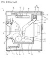
- FIG. 1 is a longitudinal sectional view illustrating the internal structure of a conventional washing and drying machine.
- the conventional washing and drying machine as shown in FIG. 1, comprises a tub 10 installed in a cabinet 2 and supported by springs 4 and dampers 6, a drum 20 installed in the tub 10 for containing laundry, a door 22 connected to the cabinet 2 for opening and closing the front surface of the drum 20, a heater duct 30 installed on the tub 10 for discharging hot air to the tub 10 and having a heater 26 and an air blower 27 installed therein, and a condensation duct 40, one end of which is connected to the lower part of a side surface of the tub 10, and, the other end of, which is connected to the heater duct 30, for condensing moisture in circulated air.
- a gasket 12, which contacts the door 22 when the door 22 is closed, is installed on the tub 10.
- the heater duct 30 is connected to the gasket 12.
- a motor 14 for rotating the drum 20 is installed on the tub 10.
- a water supply device 15 for supplying washing water or rinsing water to the inside of the tub 10 in a washing operation or a rinsing operation is connected to the tub 10.
- a drainage device 16 is connected to the lower part of the tub 10.
- the drainage device 16 comprises a drainage bellows 17 connected to the lower part of the tub 10, a drainage pump 18 connected to the drainage bellows 17, and a drainage hose 19 connected to the drainage pump 18.
- Through holes 22 for passing washing water or air are formed through the circumferential surface or the rear surface of the drum 20.
- Lifters 24 for moving laundry are installed on the inner circumferential surface of the drum 20.
- the air blower 27 comprises a circulation fan 28 rotatably disposed in the heater duct 30, and a fan motor 29 installed in the heater duct 30 for rotating the circulation fan 28.
- a cooling water supply unit 42 for supplying cooling water to the inside of the condensation duct 40 so that moisture in the circulated air obtained by drying the laundry is condensed is connected to the condensation duct 40.
- the cooling water supply unit 42 comprises a cooling water valve 44 connected to an external hose 43 for intermitting the cooling water supplied from the external hose 43, and a cooling water hose 45 for guiding the cooling water having passed through the cooling water valve 44 to the inside of the condensation duct 40.
- washing water is supplied to the washing and drying machine through the water supply device 15.
- the washing water is supplied to the inside of the tub 10 and is contained in the tub 10. Then, the washing water flows to the inside of the drum 20 through the through holes 22 of the drum 20 so that the laundry in the drum 20 is submerged in the washing water.
- the contaminated washing water in the tub 10 is discharged to the outside of the washing and drying machine through the drainage device 16.
- a rinsing operation for eliminating foam remaining in the laundry is repeated several times.
- the water supply device 15 and the motor 14 are controlled so that foam remaining in the laundry is eliminated, and the contaminated water containing the foam is discharged to the outside of the washing and drying machine through the drainage device 16.
- a dehydrating operation for centrifugally dehydrating the laundry is performed.
- the motor 14 is driven at a high speed so that the laundry is centrifugally dehydrated, and the water obtained by dehydrating the laundry is discharged to the outside of the washing and drying machine through the drainage device 16.
- the motor 14 is driven to rotate the drum 20, and the laundry in the drum 20 is agitated.
- the heater 26 is switched on to increase the temperature of peripheral air, the fan motor 29 is driven to rotate the circulation fan 28, and the cooling water valve 44 and the drainage pump 18 are repeatedly switched on and off at a designated time interval.
- the air in the drum 20 contacts the laundry by the rotation of the circulation fan 18, and is converted into a low-temperature and high-humidity state by receiving heat and moisture of the laundry. Then, the air in the low-temperature and high-humidity state flows to a space between the drum 20 and the tub 10 through the through holes 22, and is introduced into the condensation duct 40. When the air passes through the condensation duct 40, moisture contained in the air is condensed by cooling water in the condensation duct 40.
- the air When the air, having passed through the condensation duct 40, passes through the heater duct 30, the air is heated by the heater 26 and is converted into hot air.
- the hot air passes through the gasket 12, is discharged to the inside of the gasket 12, and is circulated into the drum 20. Thereafter, the above circulation is repeated, thereby drying the laundry.
- the cooling water which is supplied to the condensation duct 40, passes through the condensation duct 40, is collected in the tub 10, and is periodically pumped by the drainage pump 18, thereby being discharged to the outside.
- the heater 26 is switched off, and the drum 20 and the circulation fan 28 are circulated so that drying of the laundry using cold air is performed.
- the cooling water is periodically supplied to the conventional washing and drying machine, and discharged to the outside regardless of the load and the temperature of the cooling water, the cooling water consumption rate and the electric power consumption rate are increased. Further, the drying of the laundry using cold air is performed at a designated time, when the load of the laundry is small, the overall drying time is lengthened, and when the load of the laundry is large, the laundry is not sufficiently cooled, thereby causing users to be burned.
- the cooling water is supplied to the conventional washing and drying machine, and discharged to the outside at a designated time interval in the drying operation, the temperature of peripheral air and the temperature of the cooling water are not compensated for.
- the conventional washing and drying machine cannot cope with various load conditions, and has a limit in efficiently performing the drying operation.
- the present invention has been made in view of the above problems, and it is an object of the present invention to provide a drying control method of a washing and drying machine, in which cooling water dropped from a condensation duct to a tub accelerates the condensation of moisture contained in circulated air, thereby improving condensing capability and minimizing a cooling water consumption rate and a power consumption rate.
- a drying control method of a washing and drying machine in which air in a drum is circulated so that the air sequentially passes through a tub, a condensation duct, and a heater duct, and is introduced again to the inside of the drum, and dries laundry in the drum, comprising: supplying cooling water for condensing moisture contained in the circulated air to the condensation duct; measuring a temperature of the cooling water dropped from the condensation duct to the tub, or a temperature of the circulated air; and discharging the cooling water from the tub to the outside of the tub, when the measured temperature is more than a designated temperature.
- a drying control method of a washing and drying machine comprising: drying laundry in a drum using hot air; and drying the laundry in the drum using cold air after the drying of the laundry using the hot air, wherein, in the drying of the laundry using the cold air, the circulation of air is terminated when a temperature of the circulation air is less than a designated cold air drying termination temperature.
- a drying control method of a washing and drying machine which controls a circulation fan for causing air in a drum to sequentially pass through a tub, a condensation duct, and a heater duct and to be introduced again into the drum, a cooling water valve for supplying cooling water to the condensation duct so that moisture contained in the air passing through the condensation duct is condensed by the cooling water, and a heater for heating the air passing through the heater duct, wherein: ON/OFF conditions of the circulation fan, the cooling water valve, and the heater are determined according to the input of kind, drying time, and dryness of laundry to be dried, and when one mode out of a rapid drying mode, a power saving mode, and a water saving mode is inputted to the washing and drying machine, the ON/OFF condition of at least one of the circulation fan, the cooling water valve, and the heater is changed according to the inputted mode.
- a drying control apparatus of a washing and drying machine comprising: a tub having a drum installed therein for containing laundry so that the laundry is washed or dried; a condensation duct connected to one side of the tub for eliminating moisture contained in air drying the laundry by condensation; a heater duct connected to the upper end of the condensation duct and the other side of the tub for heating the air having passed through the condensation duct and circulating the air into the tub; an air temperature sensor for measuring a temperature of the air dehumidified by passing through the condensation duct; a cooling water temperature sensor installed at the lower end of the tub or at an inlet of the condensation duct for measuring the temperature of cooling water; and control means for receiving results sensed by the air temperature sensor and the cooling water temperature sensor and controlling the drying of the laundry using a difference between the temperature of the air and the temperature of the cooling water.
- a drying control apparatus of a washing and drying machine in which: when air drying laundry passes through a condensation duct after a drying operation for drying the laundry is started, a temperature of cooling water condensing moisture contained the air and a temperature of the air dehumidified by passing through the condensation duct are measured, and when the drying operation is continued, the dried state of the laundry is determined by a difference temperature between a signal representing characteristics of the temperature of the cooling water and a signal representing characteristics of the temperature of the air, so as to control the drying operation.
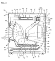
- FIG. 2 is a longitudinal sectional view illustrating the internal structure of a washing and drying machine in accordance with the present invention.
- FIG. 3 is another longitudinal sectional view illustrating the internal structure of the washing and drying machine in accordance with the present invention.
- FIG. 4 is a sectional view of another installation state of a cooling water temperature sensor of FIG. 3.
- the washing and drying machine of the present invention comprises a cabinet 52 provided with a laundry entrance hole for placing or taking laundry (m) into and out of the machine, a tub 60 installed in the cabinet 52, a drum 80 installed in the tub 60 for containing the laundry, a motor 90 installed on the tub 60 for supporting/rotating the drum 80, a door 100 connected to the cabinet 52 for opening and closing the front surface of the drum 80, a heater duct 110 installed above the tub 60 for discharging hot air to the tub 60 and having a heater 103 and an air blower 106 provided therein, a condensation duct 120 connected to the tub 60 and the heater duct 110 for condensing moisture of air, and a cooling water supplier 130 for supplying cooling water for condensing the moisture of the air to the condensation duct 120.
- the cabinet 52 forms the external appearance of the washing and drying machine, and a control panel 53 for controlling various operations of the washing and drying machine and time is installed on the upper portion of the front surface or the upper surface of the cabinet 52.
- the cabinet 52 comprises a base pan 54, a cabinet main body 55 installed on the base pan 54, a cabinet cover 56 installed in front of the cabinet main body 55, and a top plate 57 installed on the cabinet main body 55.
- the tub 60 is installed in the cabinet 52 using dampers 61 and springs 62, which are connected to the cabinet 52, so that impact applied to the tub 60 can be absorbed.
- An opening 63 is formed through the tub 60 in the rear of the laundry entrance hole 51, and the tub 60 is horizontally installed in the cabinet 52.
- a gasket 64 which is installed on the opening 63 and the laundry entrance hole 51 and contacts the door 10 when the door 100 is closed, is provided on the tub 60.
- a duct communication hole 65, to which the heater duct 100 is connected, is protruded from the gasket 64.
- a water supply hole 66 is formed through one side of the upper portion of the tub 60, and a water supply device is connected to the water supply hole 66.
- the water supply device comprises a water supply valve 68 installed in the cabinet 52 and connected to an external hose 67 for intermitting water supplied through the external hose 67, a water supply hose 69 connected to the water supply valve 68 for guiding the water having passed through the water supply valve 68, a detergent storage 70 connected to the water supply hose 69 so that the water guided by the water supply hose 69 is mixed with a detergent and having a water supply channel, a detergent receiving portion, and a discharge hole, and a water supply bellows 71 connected to the detergent storage 70 and the water supply hole 66 for guiding washing water, which is mixed with the detergent, having passed through the detergent storage 70 or rinsing water, which is not mixed with the detergent, to the water supply hole 66 of the tub 60.
- a drainage hole 72 is formed through one side of the lower portion of the tub 60, and a drainage device is connected to the drainage hole 72.
- the drainage device comprises a drainage bellows 73 connected to the drainage hole 72 of the tub 60, a drainage pump 74 connected to the drainage bellows 73, and a drainage hose 75 connected to the drainage pump 74 and extended to the outside of the washing and drying machine.
- a washing heater 76 for heating the washing water in the tub 60 in a washing operation is installed in the tub 60.
- a heater-receiving groove 77 for receiving the washing heater 76 is formed in the central area of the bottom of the tub 60.
- a tub temperature sensor 78 for measuring the temperature of the washing heater 76 so as to interrupt current applied to the washing heater 76 when the washing heater 76 is superheated is installed in the washing heater 76.
- An opening 81 is formed through the drum 80 in the rear of the laundry entrance hole 51, and the drum 80 is horizontally installed in the tub 60.
- Through holes 82 are formed through the circumferential surface or the rear surface of the drum 80.
- Lifters 83 for moving the laundry are installed on the inner circumferential surface of the drum 80.
- the motor 90 comprises a stator installed on the rear surface of the tub 60, a rotor rotated by magnetic force formed between the stator and the rotor, and the drive shaft axially installed on the rotor, passing through the through hole formed through the rear surface of the tub 60, and connected to the rear surface of the drum 80.
- the door 100 comprises a door frame 101 rotatably connected to the cabinet 52 and provided with an opening formed through the central area thereof, and a door glass 103 installed on the door frame 101 and protruded from the door frame 101 towards the drum 80.
- the air blower 106 comprises a circulation fan 107 rotatably disposed in the heater duct 110, and a fan motor 108 installed on the heater duct 110 for rotating the circulation fan 107.
- a heater air temperature sensor 112 for measuring the temperature the air heated by the heater 103 to prevent the laundry (m) from being damaged due to the overheating of the air circulating to the drum 80 is installed in the heater duct 110.
- a condensed air temperature sensor 122 for measuring the temperature of the air condensed by the cooling water through the condensation duct 120 to control a drying operation is installed in the upper portion of the condensation duct 120.
- the condensed air temperature sensor 122 is installed between an inlet of the circulation fan 107 and a cooling water inlet 134 so as to appropriately measure the temperature of the air without contacting drops of the cooling water, thereby measuring the temperature of the air sufficiently exchanging heat with the cooling water.
- a cooling water temperature sensor 123 or 123' is installed in the lower part of the condensation duct 120 at a position just after the duct communication hole 79.
- the cooling water temperature sensor 123 may be installed at the upper portion of the inside of the lower part of the condensation duct 120, thereby not contacting cooling water so that the cooling water temperature sensor 123 is not influenced by water drops generated by the condensation of moisture contained in air.
- the cooling water temperature sensor 123' may be installed in a cooling water chamber 125 installed under the condensation duct 120' so that the cooling water temperature sensor 123' is submerged in the cooling water.
- the cooling water chamber 125 comprises a hose 126 and a valve 127 for discharging the cooling water so as to prevent the cooling water from being collected in the cooling water chamber 125.
- the cooling water supplier 130 comprises a cooling water valve 132 connected to an external hose 131 for intermitting the cooling water supplied through the external hose 131, and a cooling water hose 133 for guiding the cooling water having passed through the cooling water valve 132 to the inside of the condensation duct 120.
- a water level sensing unit for sensing the water level in the tub 60 is installed in the washing and drying machine.
- the water level sensing unit comprises a water level sensing bellows 135 connected to one end of the drainage bellows 73, an air chamber 136 having a lower end connected to the water level sensing bellows 135 and filled with air compressed according to the level of water filling the water level sensing bellows 135, a water level sensing tube 137 having a lower end connected to one end of the air chamber 136, and a water level sensor 138, to which the upper end of the water level sensing tube 137 is connected, for sensing the water level by sensing the pressure of the air in the water level sensing tube 137.
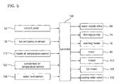
- FIG. 5 is a control block diagram of a washing and drying machine, to which a drying control method in accordance with a first embodiment of the present invention is applied.
- the washing and drying machine further comprises a controller 140 for controlling the water supply valve 68, the drainage pump 74, the washing heater 76, the motor 90, the heater 103, the fan motor 108, and the cooling water valve 132 according to instructions inputted via the control panel 53.
- the controller 140 controls the water supply valve 68, the motor 90, the drainage pump 74, and the washing heater 76 so that washing and rinsing operations are performed.
- the controller 140 controls the motor 90 and the drainage pump 74 so that a dehydrating operation is performed.
- the controller 140 controls the motor 90 and the heater 103, and controls the drainage pump 74, the fan motor 108, and the cooling water valve 132 according to a temperature (T) sensed by at least one of the tub temperature sensor 78, the heater air temperature sensor 112, and the condensed air temperature sensor 122 for forming automatic drying algorithm. Thereby, a drying operation is performed.
- the controller 140 may use the temperature (T) sensed by any one of the tub temperature sensor 78, the heater air temperature sensor 112, and the condensed air temperature sensor 122, and may use the temperatures (T) sensed by all of the tub temperature sensor 78, the heater air temperature sensor 112, and the condensed air temperature sensor 122.
- the tub temperature sensor 78 will be used in an initial or middle stage of the drying operation (i.e. in a hot air drying mode), and one of the heater air temperature sensor 112 and the condensed air temperature sensor 122, particularly, the heater air temperature sensor 112, will be used in a last stage of the drying operation (i.e. in a cold air drying mode).
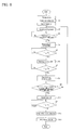
- FIG. 6 is a flow chart illustrating the drying control method of the washing and drying machine in accordance with the first embodiment of the present invention
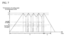
- FIG. 7 is a graph illustrating water supply/drainage times of the drying control method of the washing and drying machine in accordance with the first embodiment of the present invention.
- the hot air drying mode (H) is first performed, and the cold air drying mode (C) is then performed.
- the cold air drying mode (C) is completed, the overall drying operation is terminated.
- the controller 140 drives the motor 90 so that the drum 80 is rotated to agitate the laundry (m) in the drum 80, drives the fan motor 108 so that the circulation fan 107 is rotated to cause the air in the drum 80 to sequentially pass through the through holes 82 of the drum 80, the tub 60, the condensation duct 120, and the heater duct 110 and to be circulated into the drum 80, and switches the heater 103 on so that the air passing through the heater duct 110 is heated by the heater 103 (S1).
- the controller 140 switches the cooling water valve 132 on so that the cooling water is supplied to the condensation duct 120 and moisture contained in the air passing through the condensation duct 120 is condensed by the cooling water (S2).
- the air in the drum 80 moves towards the through holes 82 by the rotation of the circulation fan 107, contacts the laundry (m) agitated in the drum 80, and robs the laundry (m) of moisture, thereby being converted into a low-temperature and high-humidity state.
- the air moves to a space between the outer cylindrical surface of the drum 80 and the inner cylindrical surface of the tub 60, and then moves to the condensation duct 120.
- the air in the low-temperature and high-humidity state moved to the condensation duct 120 is robbed of heat by the cooling water dropped from the condensation duct 120 so that moisture contained in the air is condensed into water, moves to the condensation duct 110, and is heated by the heater 103 in the condensation duct 110, thereby being converted into a high-temperature and low-humidity state.
- the air in the high-temperature and low-humidity state passes through the gasket 64, and is circulated into the drum 80.
- the controller 140 switches the cooling water valve 132 off so that the supply of the cooling water is stopped (S3 and S4).
- the designated water level (h), as shown in FIG. 3, is a water level limit of the cooling water dropping from the condensation duct 120, which is contained in the tub 60.
- the designated water level (h) is set to be higher than the inner lower surface of the tub 60, i.e., the upper end of the drainage hole 72 so that moisture contained in the air moving to the lower portion of the inside of the tub 60 is condensed by the cooling water contained in the lower portion of the inside of the tub 60, and to be lower than the outer lower surface of the drum 80 so that the cooling water contained in the lower portion of the inside of the tub 60 is not introduced into the drum 80 through the through holes 82 of the drum 80.
- the air which is introduced into the condensation duct 120, passes through the condensation duct 120, and is introduced into the heater duct 110.
- the air passes through the heater duct 110, the air is heated by the heater 103, and is converted into a high-temperature and low-humidity state. Then, the air in the high-temperature and low-humidity state passes through the gasket 64, and is circulated into the drum 80.
- the temperature of the circulated air (denoted in the solid line) or the cooling water contained in the lower portion of the inside of the tub 60 is increased according to the decrease in heat absorption rate/ moisture condensation rate of the cooling water, as shown in FIG. 7.
- the controller 140 compares the temperature (T) measured by the tub temperature sensor 78 to a first designated temperature (T1), and, when the temperature (T) is more than the first designated temperature (T1), switches the drainage pump 74 on (S5 and S6).
- the drainage pump 74 When the drainage pump 74 is switched on, the cooling water contained in the lower portion of the inside of the tub 60 is discharged to the outside of the washing and drying machine through the drainage hose 75.
- the controller 140 compares the temperature (T) measured by the tub temperature sensor 78 to a second designated temperature (T2), and, when the temperature (T) is more than the second designated temperature (T2), switches the drainage pump 74 off (S7 and S8).
- the controller 140 switches the cooling water valve 132 on for re-supplying the cooling water, thereby re-supplying the cooling water to the washing and drying machine (S9 and S2).
- the controller 140 switches the cooling water valve 132 off again, thereby stopping the re-supply of the cooling water (S3 and S4).
- the controller 140 compares the temperature (T) measured by the tub temperature sensor 78 to the first designated temperature (T1), and switches the drainage pump 74 on according to the compared results so that the cooling water is re-discharged to the outside of the washing and drying machine. Then, the controller 140 compares the temperature (T) measured by the tub temperature sensor 78 to the second designated temperature (T2), and switches the drainage pump 74 off according to the compared results so that re-discharge of the cooling water is stopped.
- controller 140 compares the time of the hot air drying mode to the designated hot air drying time or the supply/discharge frequency of the cooling water to the designated frequency, and repeats the supply/discharge of the cooling water according to the compared results (S5, S6, S7, S8, and S9).
- the controller 140 switches the heater 103 off, thereby performing the cold air drying mode (C) (S9 and S10).
- the heater 103 is switched off, and only the circulation fan 107 is continuously rotated. Then, the air in the drum 80 is circulated into the tub 60, the condensation duct 120, the heater duct 110, and the drum 80, thus gradually lowering the temperature of the laundry (m).
- the controller 140 compares the temperature (T) measured by the heater air temperature sensor 112 to a designated cold air drying termination temperature (T3) so that the cold air drying time is adjusted according to load, and, when the temperature (T) is less than the designated cold air drying termination temperature (T3), switches the fan motor 108 off, thereby terminating the circulation of the air in the drum 80 (S11 and S12).
- the designated cold air drying termination temperature (T3) is a temperature for determining whether or not the cold air drying mode (C) is terminated.
- controller 140 switches the motor 90 off, thereby terminating the overall drying operation including the cold air drying mode.
- the drying control method of the washing and drying machine in accordance with the first embodiment of the present invention improves condensing efficiency and minimizes an overall drying time and a power consumption rate.
- the drying control method of the washing and drying machine in accordance with the first embodiment of the present invention minimizes a cooling water consumption rate.
- the drying control method of the washing and drying machine in accordance with the first embodiment of the present invention shortens the drying time when the load is small, and increases the drying efficiency and prevents burns of consumers when the load is large.
- FIG. 8 is a control block diagram of a washing and drying machine, to which a drying control method in accordance with a second embodiment of the present invention is applied.
- the washing and drying machine further comprises the controller 140 for controlling the water supply valve 68, the drainage pump 74, the washing heater 76, the motor 90, the heater 103, the fan motor 108, and the cooling water valve 132 according to washing, rinsing, dehydrating and drying instructions inputted via the control panel 53.
- the controller 140 controls the water supply valve 68, the motor 90, the drainage pump 74, and the washing heater 76 so that washing and rinsing operations are performed.
- the controller 140 controls the motor 90 and the drainage pump 74 so that a dehydrating operation is performed.
- the controller 140 When kind (for controlling the drying temperature), drying time, and dryness of laundry to be dried are inputted via the control panel 53, the controller 140 performs a drying operation according to drying conditions suitable for the inputted data. Then, when one mode out of a rapid drying mode, a power saving mode, and a water saving mode is additionally inputted via the control panel 53, the controller 140 can perform the drying operation by changing the drying conditions according to the inputted mode. Further, when one mode out of the rapid drying mode, the power saving mode, and the water saving mode is additionally inputted via the control panel 53 regardless of the input of the kind, the drying time, and the dryness of laundry to be dried, the controller 140 can perform the drying operation according to the inputted mode.
- the drying operation is performed according to the input of one mode out of the rapid drying mode, the power saving mode, and the water saving mode as well as the input of the kind, the drying time, and the dryness of laundry to be dried.
- the controller 140 controls the switching on/off of the motor 90, the drainage pump 74, the heater 103, the fan motor 108, and the cooling water valve 132 so that the overall drying time is maximally shortened in the rapid drying mode, controls the switching on/off of the motor 90, the drainage pump 74, the heater 103, the fan motor 108, and the cooling water valve 132 so that the power consumption rate is minimized in the power saving mode, and controls the switching on/off of the motor 90, the drainage pump 74, the heater 103, the fan motor 108, and the cooling water valve 132 so that the water consumption rate is minimized in the water saving mode.
- FIG. 9 is a flow chart illustrating the drying control method of the washing and drying machine in accordance with the second embodiment of the present invention.
- the controller 140 sets drying conditions according to the inputted kind, drying time, and dryness of the laundry (S1).
- the controller 140 changes the drying conditions according to the inputted mode and sets the changed drying conditions as new drying conditions (S2 and S3).
- the controller 140 switches the motor 90, the drainage pump 74, the heater 103, the fan motor 108, and the cooling water valve 132 on and/or off according to the set new drying conditions, thereby performing the drying operation (S4).
- the controller 140 switches the motor 90, the drainage pump 74, the heater 103, the fan motor 108, and the cooling water valve 132 on and/or off according to general drying conditions based on the kind, the drying time, and the dryness of laundry to be dried (S2 and S5).
- At least one of an initial cooling water supply time, a cooling water supply cycle, a cooling water discharge cycle, and a cold air drying time is set to a different value.
- Table 1 Mode Initial cooling water supply time Cooling water supply cycle Cooling water discharge cycle Cold air drying time Drying time Power consumption rate Water consumption rate Rapid drying mode 1 1 1 1 100 106 310 Power saving mode 1 2 3 2 104 100 166 Water saving mode 2 3 3 1 108 106 100
- the cooling water serves to dehumidify the circulated air.
- the cooling water decreases the temperatures of the drum, the tub, and the heater duct (hereinafter, collectively referred to a "system"), the cooling water is not necessary until the inside of the drum is fully dried due to the increase in the temperature of the system more than a designated temperature, and causes heat loss.
- the initial supply of the cooling water is performed when the temperature of the system is more than a designated temperature.
- the initial supply of the cooling water in the rapid drying mode and the power saving mode, is performed relatively early so that the drying time is minimized or the power consumption rate is minimized, and in the water saving mode, the initial supply of the cooling water is performed relatively late so that the water consumption rate is minimized.
- the supply cycle (ON/OFF) of the cooling water relates to the drying time, the power consumption rate and the water consumption rate. Accordingly, as the supply amount of the cooling water is increased, the drying time is shortened and the power consumption rate and the water consumption rate are increased.
- the cooling water supply cycle in the rapid drying mode, is the most shortened to shorten the drying time so that the power consumption rate and the water consumption rate are increased.
- the cooling water supply cycle is longer than that in the rapid drying mode so that the drying time is relatively increased and the power consumption rate and the water consumption rate are decreased.
- the cooling water supply cycle is the longest so that the drying time is the most increased and the power consumption rate and the water consumption rate are decreased.
- the discharge cycle (ON/OFF) of the cooling water relates to the time when the cooling water is collected in the tub. Since the circulated air is dehumidified by the cooling water contained in the lower portion of the tub, as the discharge amount of the cooling water is increased, the drying time is relatively shortened and the power consumption rate and the water consumption rate are increased.
- the cooling water discharge cycle is shortened to shorten the drying time so that the power consumption rate and the water consumption rate are increased.
- the cooling water discharge cycle is relatively lengthened so that the power consumption rate and the water consumption rate are decreased.
- the cold air drying time is a time when the heater is switched off, the cooling water is not supplied to the washing and drying machine, and only the circulation fan is rotated, so that laundry in the drum is dried using heat remaining in the laundry. As the cold air drying time is increased, the power consumption rate is minimized and the drying time is increased.
- the cold air drying time is increased and the hot air drying time is relatively decreased so that the power consumption rate is minimized
- the cold air drying time is decreased to shorten the drying time
- the cold air drying time is decreased to ensure a sufficient hot air drying time.
- the supply and discharge of the cooling water and the cold air drying operation may be performed respectively in the rapid drying mode, the power saving mode, and the water saving mode according to a predetermined designated program or according to the temperature of the cooling water or the circulated air.
- a predetermined designated program or according to the temperature of the cooling water or the circulated air.
- the controller 140 controls the motor 90, the drainage pump 74, the heater 103, the fan motor 108, and the cooling water valve 132 according to the temperature (T) sensed by at least one of the tub temperature sensor 78, the heater air temperature sensor 112, and the condensed air temperature sensor 122.
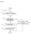
- FIG. 10 is a flow chart illustrating the drying control method of the washing and drying machine in accordance with the second embodiment of the present invention, in one mode out of the rapid drying mode, the power saving mode, and the water saving mode.
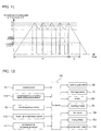
- FIG. 11 is a graph illustrating cooling water supply/discharge times and temperature of the cooling water or circulated air according to the cold air drying operation when the drying control method in accordance with the second embodiment of the present invention is in one mode out of the rapid drying mode, the power saving mode, and the water saving mode.
- the controller 140 first performs the hot air drying operation (H), and then performs the cold air drying operation (C) after the hot air drying operation (H). When the cold air drying operation (C) is completed, the overall drying operation is terminated.
- the controller 140 drives the motor 90 so that the drum 80 is rotated to agitated the laundry (m) in the drum 80, drives the fan motor 108 so that the circulation fan 107 is rotated to cause the air in the drum 80 to sequentially pass through the through holes 82 of the drum 80, the tub 60, the condensation duct 120, and the heater duct 110 and to be circulated into the drum 80, and switches the heater 103 on so that the air passing through the heater duct 110 is heated by the heater 103 (S11).
- the air in the drum 80 moves towards the through holes 82 by the rotation of the circulation fan 107, contacts the laundry (m) agitated in the drum 80, and robs the laundry (m) of moisture, thereby being converted into a low-temperature and high-humidity state.
- the air moves to a space between the outer cylindrical surface of the drum 80 and the inner cylindrical surface of the tub 60, and then passes through the condensation duct 120.
- the air in the low-temperature and high-humidity state, having passed through the condensation duct 120, is introduced into the heater duct 110, and is heated by the heater 103, thereby being converted into hot air.
- the hot air passes through the gasket 64, and is circulated into the drum 80 to rob the laundry (m) of moisture.
- the temperature of the air is gradually increased, as shown in FIG. 11.
- the controller 140 compares the temperature of the circulated air to the first designated temperature (T1) in order to determine whether or not the cooling water is initially supplied to the washing and drying machine during the drying operation (S12).
- the controller 140 compares the temperature (T, hereinafter, referred to as the temperature of the circulated air), which is measured by one of the heater air temperature sensor 112 of the heater duct 110 and the condensed air temperature sensor 122 of the condensation duct 120, to the first designated temperature (T1).
- T the temperature of the circulated air
- the controller 140 switches the cooling water valve 132 on.
- the cooling water valve 132 When the cooling water valve 132 is switched on, the air in the low-temperature and high-humidity state, which moves into the condensation duct 120, is robbed of heat by the cooling water supplied to the condensation duct 120, and is converted into a low-humidity state. Further, the temperature of the air is gradually decreased, as shown in FIG. 11.
- the controller 140 re-compares the temperature (T) of the circulated air to the first designated temperature (T1) in order to determine whether or not the supply of the cooling water is stopped during the drying operation (S14).
- the controller 140 switches the cooling water valve 132 off so that the supply of the cooling water is stopped (S15).
- the cooling water supplied to the condensation duct 120 drops towards the lower portion of the inside of the tub 60, and, even when the supply of the cooling water is stopped, the circulated air is continuously robbed of heat by the cooling water collected in the lower portion of the inside of the tub 60 so that moisture contained in the circulated air is condensed into water, and continuously dries the laundry.
- the temperature of the circulated air gradually decreases.
- the temperature of the circulated air is the same as that of the cooling water due to the decrease in heat absorption rate/moisture condensation rate of the cooling water, as shown in FIG. 11, the temperatures of the cooling water and the circulated air are increased again.
- the controller 140 compares the temperature (T) of the cooling water to the second designated temperature (T2, here, T2 > T1) in order to determine whether or not the cooling water is discharged to the outside of the washing and drying machine (S16).
- the controller 140 compares the temperature measured by the tub temperature sensor 78 (T, hereinafter, referred to as the temperature of the cooling water) to the second designated temperature (T2).
- the controller 140 switches the drainage pump 74 on (S17).
- the drainage pump 74 When the drainage pump 74 is switched on, the cooling water collected in the lower portion of the inside of the tub 60 is discharged to the outside of the washing and drying machine through the drainage bellows 73, the drainage pump 74, and the drainage hose 75, and the temperature of the circulated air is continuously increased, as shown in FIG. 11.
- the controller 140 compares the temperature of the circulated air to the third designated temperature (T3, here, T3 > T2) in order to determine whether or not the discharge of the cooling water is stopped (S18).
- the controller 140 compares the temperature (T, hereinafter, referred to as the temperature of the circulated air) measured by one of the heater air temperature sensor 112 of the heater duct 110 and the condensed air temperature sensor 122 of the condensation duct 120 to the third designated temperature (T3).
- the controller 140 switches the drainage pump 74 off so that the discharge of the cooling water is stopped (S19).
- the controller 140 switches the cooling water valve 132 on again for supplying cooling water, thereby re-supplying the cooling water to the washing and drying machine (S20 and S21).
- the controller 140 compares the temperature (T) of the circulated air to a fourth designated temperature (T4, here, T4 ⁇ T1) in order to determine whether or not the re-supply of the cooling water is stopped during the drying operation (S22).
- the controller 140 switches the cooling water valve 132 off so that the re-supply of the cooling water is stopped (S23).
- the cooling water re-supplied to the condensation duct 120 drops towards the lower portion of the inside of the tub 60, and, even when the supply of the cooling water is stopped, the circulated air is continuously robbed of heat by the cooling water collected in the lower portion of the inside of the tub 60 so that moisture contained in the circulated air is continuously condensed into water, and continuously dries the laundry.
- the controller 140 compares the temperature (T) of the cooling water to the second designated temperature (T2) in order to determine whether or not the cooling water is re-discharged to the outside of the washing and drying machine, and, when the temperature (T) of the cooling water is more than the second designated temperature (T2), switches the drainage pump 74 on so that the cooling water is re-discharged to the outside of the washing and drying machine (S24 and S25).
- the controller 140 compares the temperature of the circulated air to the third designated temperature (T3) in order to determine whether or not the discharge of the cooling water is stopped, and, when the temperature (T) of the circulated air is more than the third designated temperature (T3), switches the drainage pump 74 off so that the re-discharge of the cooling water is stopped (S26 and S27).
- the controller 140 repeats the re-supply and re-discharge of the cooling water (S28, S21, S22, S23, S24, S25, S26, and S27).
- the controller 140 switches the heater 103 off so that the cold air drying operation (C) is performed (S29).
- the controller 140 switches the heater 103 off, and continuously rotates only the circulation fan 107. Then, the air in the drum 80 is circulated into the tub 60, the condensation duct 120, the heater duct 110, and the drum 80, thereby gradually decreasing the temperature of the laundry (m).
- the controller 140 compares the temperature (T) measured by the heater air temperature sensor 112 to a fifth designated temperature (T5, here, T5 ⁇ T1) in order to adjust the cold air drying time according to the load, and, when the temperature (T) is less than the fifth designated temperature (T5), switches the fan motor 108 off so that the circulation of the air in the drum 80 is terminated (S30 and S31).
- the fifth designated temperature (T5) is a temperature for determining whether or not the cold air drying operation is terminated.
- controller 140 switches the motor 90 off, thereby terminating the overall drying operation including the cold air drying operation (S32).
- the controller 140 sets the first to fifth designated temperatures to different values, thereby maximally shortening the overall drying time, minimizing the power consumption rate, or minimizing the water consumption rate.
- the controller 140 sets the first designated temperature to a relatively low value so that the initial supply of the cooling water is performed early, sets the second and third designated temperatures to relatively low values so that the cooling water discharge cycle is shortened, sets the fourth designated temperature to a relatively high value so that the cooling water supply cycle is shortened, and sets the fifth designated temperature to a relatively high value so that the cold air drying time is shortened.
- the drying operation in the rapid drying mode is rapidly completed compared to the drying operation in the power saving mode or the water saving mode.
- the drying control method of the washing and drying machine in accordance with the second embodiment of the present invention when one of the rapid drying mode, the power saving mode, and the water saving mode is inputted to the washing and drying machine, the drying operation is performed according to the inputted mode. Accordingly, the drying control method in accordance with the second embodiment can rapidly perform the drying operation, minimize the power consumption rate, or minimize the cooling water consumption rate according to user's desire, thereby increasing convenience in using the washing and drying machine.
- the drying control method in accordance with the second embodiment performs the drying operation only when a user selects one of the rapid drying mode, the power saving mode, and the water saving mode.
- the drying control method in accordance with the second embodiment simply and rapidly adjusts the overall drying time, the power consumption rate, and the cooling water consumption rate.
- the drying control method in accordance with the second embodiment spontaneously and rapidly copes with variation in load.
- FIG. 12 is a control block diagram of a washing and drying machine, to which a drying control method in accordance with a third embodiment of the present invention is applied.
- the washing and drying machine comprises the controller 140 serving as control means for receiving sensed results from the air temperature sensors 112 and 122 and the cooling water temperature sensors 78 and 123 and controlling the drying of laundry, such as the drying termination time of the laundry, according to the sensed results in the drying operation.
- the controller 140 may control the overall operation of the washing and drying machine.
- the controller 140 is connected to the control panel 53 so as to input or output control signals to or from various control components, such as the water supply valve 68, the drainage pump 74, the motors 90 and 108, the heaters 76 and 103, the sensors 78, 112, 122 and 123, and the valve 132.
- the motor 90 is operated by the control signal of the controller 140 so that the drum 80 is slowly rotated, the circulation fan 106 and the drying heater 103 in the heater duct 110 are operated, and the cooling water valve 132 is opened so that the cooling water is supplied to the inside of the condensation duct 120.
- the air in the drum 80 passes through the condensation duct 120 and the heater duct 110 by the rotation of the circulation fan 106, and is circulated again to the inside of the drum 80.
- the air which contacts the laundry in the drum 80, robs the laundry of heat and moisture, thereby being converted into a low-temperature and high-humidity state.
- the air in the low-temperature and high-humidity state is introduced into the condensation duct 120, and when the air passes through the condensation duct 120, the moisture contained in the air is condensed by the cooling water so that the air is dehumidified.
- the air, having passed through the condensation duct 120 passes through the heater duct 110, and is heated by the heater 103, thereby being converted into hot air.
- the hot air is circulated again into the drum 80.
- the laundry in the washing and drying machine is dried by repeating the above process.
- FIG. 13 is a graph illustrating temperature characteristics of air and cooling water in the drying control method in accordance with the third embodiment of the present invention
- FIG. 14 is a graph illustrating temperatures sensed by sensors and differences among the sensed temperatures in an initial stage of a drying operation in the drying control method in accordance with the third embodiment of the present invention.
- Ta represents temperature characteristics of dehumidified air by passing through the condensation duct 120
- Tc represents temperature characteristics of cooling water dropped from the condensation duct 120 for dehumidifying circulation air.
- the dryness is determined using the temperature characteristics of the air and the cooling water, and the drying operation is controlled by sensing the difference between the temperatures of the air and the cooling water.
- Tout in FIG. 13 represents the temperature of the cooling water discharged to the outside of the tub 60.
- the temperature (Tc) of the cooling water, which condenses moisture contained in the air when the air drying the laundry passes through the condensation duct 120, and the temperature (Ta) of the air dehumidified by passing through the condensation duct 120 are measured.
- a temperature (Tcc) of the cooling water which passes through the lower end of the condensation duct 120 and is sensed by the condensation duct cooling water temperature sensor 123 or 123', or a temperature (Tct) of the cooling water, which is collected in the tub 60 and is sensed by the tub temperature sensor 78, may be measured. Alternately, both the temperature (Tcc) and the temperature (Tct) may be measured. Since the variation in the temperature (Tcc) of the cooling water sensed by the condensation duct cooling water temperature sensor 123 or 123' and the variation in the temperature (Tct) of the cooling water sensed by the tub temperature sensor 78 are similar to each other, FIGS. 14 and 15 illustrates only the variation in the temperature (Tct) of the cooling water sensed by the tub temperature sensor 78.
- a temperature (Tac) of the air which is dehumidified by passing through the condensation duct 120 and is sensed by the condensed air temperature sensor 122, or a temperature (Tah) of the air, which passes through the heater 103 and is sensed by the heater air temperature sensor 112 may be measured. Since the variation in the temperature (Tac) of the air sensed by the condensed air temperature sensor 122 and the variation in the temperature (Tah) of the air sensed by the heater air temperature sensor 112 are similar to each other, one or all of the measured values of the two temperatures (Tac and Tah) of the air may be used. In this embodiment, the temperature (Tac) of the air sensed by the condensed air temperature sensor 122 is used.
- the temperature (Tc) of the cooling water and the temperature (Ta) of the air are measured as described above.
- the dried state of the laundry is determined by a temperature difference (Td) between a signal representing the temperature (Tc) of the cooling water and a signal representing the temperature (Ta) of the air, thereby controlling the drying operation.
- the difference temperature (Td), the increase rate of which is less than a designated value after the drying operation is started, is set to an initial temperature (T1).
- T1 the temperature (Ta) of the air and the temperature (Tc) of the cooling water are increased at constant rates, and, the temperature (Ta) of the air is decreased after the drying of the laundry is substantially carried out.
- the curve of the difference temperature (Td) has an inflection point less than a designated value.
- the difference temperature (Td) at the inflection point is set to the initial temperature (T1).
- the difference temperature (Td) after a designated time (t1) from the start of the drying operation elapses is set to the initial temperature (T1).
- the initial temperature (T1) is determined by appropriately selecting a point of time when the drying of the laundry is substantially carried out, through experimentation, which is repeated several times.
- the drying control method of the present invention determines the drying state of the laundry, i.e., the dryness of the laundry, through the difference between the determination temperature (T2) and the initial temperature (T1). Particularly, the drying control method of the present invention determines that a time when the difference between the determination temperature (T2) and the initial temperature (T1) is more than a designated value is the drying completion time (t2), and thus completes the drying operation.
- the individual temperature characteristics are determined through temperatures of the air and the cooling water when a target difference temperature value is continued more than a designated time so as to filter the variation in temperatures due to disturbance.
- FIG. 16 is a graph illustrating the functional relation among amount of laundry, dryness of the laundry according to drying intensity, and time in the washing and drying machine in accordance with the third embodiment of the present invention.
- the determination temperature (T2) is determined by the function among the intensity of the drying mode, the inputted drying time, and the water content of laundry to be dried (the amount of water contained in the laundry to be dried).
- the drying modes include a strong drying mode, standard drying mode, and a weak drying mode.
- the determination temperature (T2) may be set to a higher value.
- the cooling water supplied to the condensation duct 120 passes through the condensation duct 120, is collected in the tub 60, and is periodically pumped out by the drainage device 74, thus, being discharged to the outside. Thereby, the drying operation is performed.
- the drying control apparatus and method of the washing and drying machine in accordance with the third embodiment of the present invention more precisely compensate for the dryness of the laundry to be dried according to load conditions, such as the temperature of the peripheral air and the temperature of the cooling water, and more efficiently control the drying operation, thereby improving the drying capability.
- the present invention provides a drying control apparatus and method of a washing and drying machine which enable a drying operation to be appropriately performed according to operating conditions.
- a drying control apparatus and method of a washing and drying machine which enable a drying operation to be appropriately performed according to operating conditions.
Landscapes
- Engineering & Computer Science (AREA)
- Textile Engineering (AREA)
- Control Of Washing Machine And Dryer (AREA)
- Main Body Construction Of Washing Machines And Laundry Dryers (AREA)
- Detail Structures Of Washing Machines And Dryers (AREA)
Applications Claiming Priority (3)
| Application Number | Priority Date | Filing Date | Title |
|---|---|---|---|
| KR1020040092560A KR100748962B1 (ko) | 2004-11-12 | 2004-11-12 | 세탁건조기/건조기의 건조 제어 방법 |
| KR1020040097561A KR100600771B1 (ko) | 2004-11-25 | 2004-11-25 | 세탁건조기의 건조 제어 방법 |
| KR1020040097562A KR100748964B1 (ko) | 2004-11-25 | 2004-11-25 | 세탁건조기의 건조 제어 방법 |
Publications (2)
| Publication Number | Publication Date |
|---|---|
| EP1657341A2 true EP1657341A2 (fr) | 2006-05-17 |
| EP1657341A3 EP1657341A3 (fr) | 2006-08-23 |
Family
ID=35788411
Family Applications (1)
| Application Number | Title | Priority Date | Filing Date |
|---|---|---|---|
| EP05024437A Withdrawn EP1657341A3 (fr) | 2004-11-12 | 2005-11-09 | Procédé et dispositif de commande d'un processus de séchage dans une machine à laver et à sécher |
Country Status (3)
| Country | Link |
|---|---|
| US (1) | US20060137105A1 (fr) |
| EP (1) | EP1657341A3 (fr) |
| JP (1) | JP2006136730A (fr) |
Cited By (12)
| Publication number | Priority date | Publication date | Assignee | Title |
|---|---|---|---|---|
| EP1967633A2 (fr) | 2007-03-06 | 2008-09-10 | Samsung Electronics Co., Ltd. | Procédé de détection de température d'eau condensée par une machine à laver et son procédé de contrôle du séchage |
| EP2019160A1 (fr) * | 2007-07-26 | 2009-01-28 | CANDY S.p.A. | Machine à laver séchante |
| EP2019162A1 (fr) * | 2007-07-26 | 2009-01-28 | CANDY S.p.A. | Machine lavante/séchante |
| EP2065510A1 (fr) * | 2007-11-28 | 2009-06-03 | CANDY S.p.A. | Machine pour traiter le linge, particulièrement une machine à laver sèche-linge avec circuit de recirculation |
| WO2011069870A1 (fr) * | 2009-12-11 | 2011-06-16 | BSH Bosch und Siemens Hausgeräte GmbH | Appareil de traitement du linge présentant une fonction séchage et son procédé de commande |
| EP2028312A3 (fr) * | 2007-08-06 | 2012-06-27 | LG Electronics Inc. | Sèche-linge |
| WO2013165109A1 (fr) | 2012-05-03 | 2013-11-07 | Lg Electronics Inc. | Machine de traitement de linge et procédé de commande de celle-ci |
| EP2749683A1 (fr) * | 2012-12-27 | 2014-07-02 | Dongbu Daewoo Electronics Corporation | Procédé et dispositif de séchage pour le séchage de linge |
| EP2227584B2 (fr) † | 2007-12-20 | 2015-01-14 | BSH Bosch und Siemens Hausgeräte GmbH | Appareil de séchage |
| EP2466002A4 (fr) * | 2009-08-11 | 2015-07-15 | Lg Electronics Inc | Sécheur et procédé de commande associé |
| US11186943B2 (en) | 2017-10-09 | 2021-11-30 | Whirlpool Corporation | Filter configured for being used in a machine for drying laundry and machine for drying laundry equipped with such a filter |
| EP4407092A3 (fr) * | 2020-03-31 | 2024-11-06 | LG Electronics Inc. | Wäschebehandlungsvorrichtung und steuerungsverfahren dafür |
Families Citing this family (65)
| Publication number | Priority date | Publication date | Assignee | Title |
|---|---|---|---|---|
| KR100700780B1 (ko) * | 2004-11-12 | 2007-03-27 | 엘지전자 주식회사 | 건조 겸용 세탁기 및 건조 겸용 세탁기의 세탁 제어 방법 |
| JP2006198149A (ja) * | 2005-01-20 | 2006-08-03 | Toshiba Corp | 乾燥機能付洗濯機 |
| DE102007007354B4 (de) | 2006-02-20 | 2013-10-10 | Lg Electronics Inc. | Wäschetrockner und Verfahren zur Steuerung |
| US7627920B2 (en) | 2006-06-09 | 2009-12-08 | Whirlpool Corporation | Method of operating a washing machine using steam |
| US7730568B2 (en) | 2006-06-09 | 2010-06-08 | Whirlpool Corporation | Removal of scale and sludge in a steam generator of a fabric treatment appliance |
| US7941885B2 (en) | 2006-06-09 | 2011-05-17 | Whirlpool Corporation | Steam washing machine operation method having dry spin pre-wash |
| US20070283509A1 (en) * | 2006-06-09 | 2007-12-13 | Nyik Siong Wong | Draining liquid from a steam generator of a fabric treatment appliance |
| US7765628B2 (en) | 2006-06-09 | 2010-08-03 | Whirlpool Corporation | Steam washing machine operation method having a dual speed spin pre-wash |
| US20070283728A1 (en) * | 2006-06-09 | 2007-12-13 | Nyik Siong Wong | Prevention of scale and sludge in a steam generator of a fabric treatment appliance |
| KR100830514B1 (ko) | 2006-06-12 | 2008-05-21 | 엘지전자 주식회사 | 건조기 및 그 제어방법 |
| US20080040869A1 (en) * | 2006-08-15 | 2008-02-21 | Nyik Siong Wong | Determining Fabric Temperature in a Fabric Treating Appliance |
| US7681418B2 (en) | 2006-08-15 | 2010-03-23 | Whirlpool Corporation | Water supply control for a steam generator of a fabric treatment appliance using a temperature sensor |
| US7841219B2 (en) * | 2006-08-15 | 2010-11-30 | Whirlpool Corporation | Fabric treating appliance utilizing steam |
| US7886392B2 (en) | 2006-08-15 | 2011-02-15 | Whirlpool Corporation | Method of sanitizing a fabric load with steam in a fabric treatment appliance |
| US7591859B2 (en) | 2006-08-15 | 2009-09-22 | Whirlpool Corporation | Water supply control for a steam generator of a fabric treatment appliance using a weight sensor |
| US7665332B2 (en) | 2006-08-15 | 2010-02-23 | Whirlpool Corporation | Steam fabric treatment appliance with exhaust |
| US7707859B2 (en) | 2006-08-15 | 2010-05-04 | Whirlpool Corporation | Water supply control for a steam generator of a fabric treatment appliance |
| US7753009B2 (en) | 2006-10-19 | 2010-07-13 | Whirlpool Corporation | Washer with bio prevention cycle |
| US20080095660A1 (en) * | 2006-10-19 | 2008-04-24 | Nyik Siong Wong | Method for treating biofilm in an appliance |
| JP2008110135A (ja) * | 2006-10-31 | 2008-05-15 | Toshiba Corp | 洗濯機 |
| US7997006B2 (en) * | 2007-01-12 | 2011-08-16 | Lg Electronics Inc. | Laundry machine and control method thereof |
| JP5095240B2 (ja) * | 2007-03-07 | 2012-12-12 | ハイアール グループ コーポレーション | 乾燥機 |
| US8393183B2 (en) | 2007-05-07 | 2013-03-12 | Whirlpool Corporation | Fabric treatment appliance control panel and associated steam operations |
| KR100880641B1 (ko) | 2007-08-13 | 2009-01-30 | 엘지전자 주식회사 | 세탁기 |
| US8555676B2 (en) | 2007-08-31 | 2013-10-15 | Whirlpool Corporation | Fabric treatment appliance with steam backflow device |
| US8555675B2 (en) | 2007-08-31 | 2013-10-15 | Whirlpool Corporation | Fabric treatment appliance with steam backflow device |
| US8037565B2 (en) * | 2007-08-31 | 2011-10-18 | Whirlpool Corporation | Method for detecting abnormality in a fabric treatment appliance having a steam generator |
| US7918109B2 (en) | 2007-08-31 | 2011-04-05 | Whirlpool Corporation | Fabric Treatment appliance with steam generator having a variable thermal output |
| US7966683B2 (en) | 2007-08-31 | 2011-06-28 | Whirlpool Corporation | Method for operating a steam generator in a fabric treatment appliance |
| US7905119B2 (en) | 2007-08-31 | 2011-03-15 | Whirlpool Corporation | Fabric treatment appliance with steam generator having a variable thermal output |
| US7861343B2 (en) | 2007-08-31 | 2011-01-04 | Whirlpool Corporation | Method for operating a steam generator in a fabric treatment appliance |
| US7690062B2 (en) | 2007-08-31 | 2010-04-06 | Whirlpool Corporation | Method for cleaning a steam generator |
| KR101020427B1 (ko) * | 2008-06-03 | 2011-03-08 | 엘지전자 주식회사 | 건조기 및 그 제어방법 |
| CA2639251A1 (fr) * | 2008-08-29 | 2010-02-28 | Mabe Canada Inc. | Secheuse et methode de defroissage des vetements avec condensation reduite |
| EP2385163B1 (fr) * | 2010-05-03 | 2016-10-05 | Electrolux Home Products Corporation N.V. | Machine à laver avec système de pompe à chaleur intégrée |
| EP2390397A1 (fr) * | 2010-05-25 | 2011-11-30 | Electrolux Home Products Corporation N.V. | Procédé de fonctionnement d'un cycle de lavage et cycle de séchage successif dans une laveuse-sécheuse de linge |
| US9080283B2 (en) * | 2011-10-06 | 2015-07-14 | Whirlpool Corporation | Method to control a drying cycle of a laundry treating appliance |
| CN104727112B (zh) * | 2013-12-24 | 2018-05-08 | 博西华电器(江苏)有限公司 | 衣物处理设备 |
| CN105483995A (zh) * | 2014-09-18 | 2016-04-13 | 博西华电器(江苏)有限公司 | 干衣机的烘干方法以及采用该烘干方法的干衣机 |
| CN105483994A (zh) * | 2014-09-18 | 2016-04-13 | 博西华电器(江苏)有限公司 | 干衣机及其烘干方法 |
| CN105483999A (zh) * | 2014-09-18 | 2016-04-13 | 博西华电器(江苏)有限公司 | 干衣机及其烘干方法 |
| DE102014219379A1 (de) * | 2014-09-25 | 2016-03-31 | BSH Hausgeräte GmbH | Verfahren zum Betrieb eines Waschtrockners mit Schutz vor Temperaturschock sowie hierzu geeigneter Waschtrockner |
| US10638295B2 (en) | 2015-01-17 | 2020-04-28 | Machinesense, Llc | System and method for turbomachinery preventive maintenance and root cause failure determination |
| US20160245686A1 (en) | 2015-02-23 | 2016-08-25 | Biplab Pal | Fault detection in rotor driven equipment using rotational invariant transform of sub-sampled 3-axis vibrational data |
| US10613046B2 (en) * | 2015-02-23 | 2020-04-07 | Machinesense, Llc | Method for accurately measuring real-time dew-point value and total moisture content of a material |
| US10648735B2 (en) | 2015-08-23 | 2020-05-12 | Machinesense, Llc | Machine learning based predictive maintenance of a dryer |
| US20160313216A1 (en) | 2015-04-25 | 2016-10-27 | Prophecy Sensors, Llc | Fuel gauge visualization of iot based predictive maintenance system using multi-classification based machine learning |
| US10599982B2 (en) | 2015-02-23 | 2020-03-24 | Machinesense, Llc | Internet of things based determination of machine reliability and automated maintainenace, repair and operation (MRO) logs |
| US20160245279A1 (en) | 2015-02-23 | 2016-08-25 | Biplab Pal | Real time machine learning based predictive and preventive maintenance of vacuum pump |
| WO2016173787A1 (fr) * | 2015-04-28 | 2016-11-03 | Arcelik Anonim Sirketi | Sèche-linge |
| JP6553448B2 (ja) * | 2015-08-19 | 2019-07-31 | 日立グローバルライフソリューションズ株式会社 | ドラム式洗濯機 |
| JP6563281B2 (ja) * | 2015-09-09 | 2019-08-21 | 青島海爾洗衣机有限公司QingDao Haier Washing Machine Co.,Ltd. | 衣類乾燥機 |
| JP2017176562A (ja) * | 2016-03-31 | 2017-10-05 | 日立アプライアンス株式会社 | 洗濯乾燥機 |
| CN107541919B (zh) * | 2016-06-27 | 2020-05-22 | 青岛海尔滚筒洗衣机有限公司 | 一种根据干衣机出筒空气温度变化调节冷凝介质量的方法 |
| JP6626795B2 (ja) * | 2016-07-28 | 2019-12-25 | 日立グローバルライフソリューションズ株式会社 | 洗濯乾燥機 |
| DE102017103498A1 (de) | 2017-02-21 | 2018-08-23 | Miele & Cie. Kg | Verfahren zum Trocknen von Wäsche, Steuerverfahren und Steuervorrichtung zum Steuern eines Trocknungsvorgangs und wasserführendes Haushaltgerät zur Wäschebehandlung |
| DE102017103500A1 (de) | 2017-02-21 | 2018-08-23 | Miele & Cie. Kg | Verfahren zum Trocknen von Wäsche, Steuerverfahren und Steuervorrichtung zum Steuern eines Trocknungsvorgangs und Waschtrockner |
| US10921792B2 (en) | 2017-12-21 | 2021-02-16 | Machinesense Llc | Edge cloud-based resin material drying system and method |
| KR20200025946A (ko) * | 2018-08-31 | 2020-03-10 | 삼성전자주식회사 | 의류 관리기 및 그 제어방법 |
| CN109629172A (zh) * | 2018-11-29 | 2019-04-16 | 惠而浦(中国)股份有限公司 | 具有蒸汽洗功能的洗衣机及其洗涤方法 |
| KR102661664B1 (ko) * | 2019-01-10 | 2024-04-29 | 엘지전자 주식회사 | 인덕션 히터를 갖는 세탁장치 |
| US11598042B2 (en) | 2019-03-28 | 2023-03-07 | Whirlpool Corporation | Laundry treating appliance with induction heat |
| US12448726B2 (en) | 2021-02-01 | 2025-10-21 | Electrolux Consumer Products, Inc. | Laundry dryer control system |
| CN113756055B (zh) * | 2021-09-28 | 2022-08-19 | 珠海格力电器股份有限公司 | 一种洗涤筒组件、洗衣机和烘干降温方法 |
| CN113756039A (zh) * | 2021-09-30 | 2021-12-07 | 珠海格力电器股份有限公司 | 一种洗干一体机及其干衣控制方法 |
Family Cites Families (15)
| Publication number | Priority date | Publication date | Assignee | Title |
|---|---|---|---|---|
| DE2624514C2 (de) * | 1976-06-01 | 1982-10-21 | Licentia Patent-Verwaltungs-Gmbh, 6000 Frankfurt | Steueranordnung für Haushaltswaschmaschinen |
| DE2654976C3 (de) * | 1976-12-03 | 1980-11-27 | Bosch-Siemens Hausgeraete Gmbh, 7000 Stuttgart | Zum Trocknen eingerichtete Wäschebehandlungsmaschine |
| US4206552A (en) * | 1978-04-28 | 1980-06-10 | Mallory Components Group Emhart Industries, Inc. | Means and method for controlling the operation of a drying apparatus |
| US4397101A (en) * | 1981-09-10 | 1983-08-09 | General Electric Company | Automatic dryer control |
| US4763425A (en) * | 1987-06-25 | 1988-08-16 | Speed Queen Company | Automatic clothes dryer |
| DE3932170A1 (de) * | 1989-09-27 | 1991-04-04 | Licentia Gmbh | Anzeigevorrichtung fuer elektrische haushaltsgeraete |
| IT221382Z2 (it) * | 1989-12-01 | 1994-03-16 | Zanussi A Spa Industrie | Dispositivo di condensazione del vapore per macchine asciugabiancheriao macchine combinate per il lavaggio e l'asciugatura della biancheria |
| EP0481442B1 (fr) * | 1990-10-16 | 1995-08-23 | Sharp Kabushiki Kaisha | Machine à laver/à sécher à tambour |
| DE4447270A1 (de) * | 1994-12-30 | 1996-07-04 | Bosch Siemens Hausgeraete | Verfahren zum Steuern von Trockenvorgängen in Haushalt-Wäschetrocknern |
| GB9917494D0 (en) * | 1999-07-27 | 1999-09-29 | Crosslee Plc | A tumble dryer |
| US6199300B1 (en) * | 2000-03-01 | 2001-03-13 | Whirlpool Corporation | Method for energy efficient control of a dryer of clothes |
| ITPN20010070A1 (it) * | 2001-10-10 | 2003-04-10 | Electrolux Zanussi Elettrodome | Macchina lavatrice-asciugatrice di biancheria |
| JP3605067B2 (ja) * | 2001-11-14 | 2004-12-22 | 三洋電機株式会社 | ドラム式洗濯乾燥機 |
| KR100955484B1 (ko) * | 2003-04-30 | 2010-04-30 | 삼성전자주식회사 | 세탁기 및 그 건조 제어방법 |
| KR100617110B1 (ko) * | 2004-04-09 | 2006-08-31 | 엘지전자 주식회사 | 건조겸용 드럼세탁기 |
-
2005
- 2005-11-09 US US11/269,807 patent/US20060137105A1/en not_active Abandoned
- 2005-11-09 EP EP05024437A patent/EP1657341A3/fr not_active Withdrawn
- 2005-11-14 JP JP2005329225A patent/JP2006136730A/ja active Pending
Cited By (18)
| Publication number | Priority date | Publication date | Assignee | Title |
|---|---|---|---|---|
| EP1967633A3 (fr) * | 2007-03-06 | 2009-12-30 | Samsung Electronics Co., Ltd. | Procédé de détection de température d'eau condensée par une machine à laver et son procédé de contrôle du séchage |
| EP1967633A2 (fr) | 2007-03-06 | 2008-09-10 | Samsung Electronics Co., Ltd. | Procédé de détection de température d'eau condensée par une machine à laver et son procédé de contrôle du séchage |
| EP2019160A1 (fr) * | 2007-07-26 | 2009-01-28 | CANDY S.p.A. | Machine à laver séchante |
| EP2019162A1 (fr) * | 2007-07-26 | 2009-01-28 | CANDY S.p.A. | Machine lavante/séchante |
| EP2028312A3 (fr) * | 2007-08-06 | 2012-06-27 | LG Electronics Inc. | Sèche-linge |
| EP2065510A1 (fr) * | 2007-11-28 | 2009-06-03 | CANDY S.p.A. | Machine pour traiter le linge, particulièrement une machine à laver sèche-linge avec circuit de recirculation |
| EP2227584B2 (fr) † | 2007-12-20 | 2015-01-14 | BSH Bosch und Siemens Hausgeräte GmbH | Appareil de séchage |
| EP2466002A4 (fr) * | 2009-08-11 | 2015-07-15 | Lg Electronics Inc | Sécheur et procédé de commande associé |
| WO2011069870A1 (fr) * | 2009-12-11 | 2011-06-16 | BSH Bosch und Siemens Hausgeräte GmbH | Appareil de traitement du linge présentant une fonction séchage et son procédé de commande |
| EP2844794A4 (fr) * | 2012-05-03 | 2015-10-28 | Lg Electronics Inc | Machine de traitement de linge et procédé de commande de celle-ci |
| CN104334789A (zh) * | 2012-05-03 | 2015-02-04 | Lg电子株式会社 | 衣物处理机及其控制方法 |
| WO2013165109A1 (fr) | 2012-05-03 | 2013-11-07 | Lg Electronics Inc. | Machine de traitement de linge et procédé de commande de celle-ci |
| AU2013255199B2 (en) * | 2012-05-03 | 2015-11-26 | Lg Electronics Inc. | Laundry treating machine and control method thereof |
| EP2749683A1 (fr) * | 2012-12-27 | 2014-07-02 | Dongbu Daewoo Electronics Corporation | Procédé et dispositif de séchage pour le séchage de linge |
| US11186943B2 (en) | 2017-10-09 | 2021-11-30 | Whirlpool Corporation | Filter configured for being used in a machine for drying laundry and machine for drying laundry equipped with such a filter |
| US11761141B2 (en) | 2017-10-09 | 2023-09-19 | Whirlpool Corporation | Filter configured for being used in a machine for drying laundry and machine for drying laundry equipped with such a filter |
| EP4407092A3 (fr) * | 2020-03-31 | 2024-11-06 | LG Electronics Inc. | Wäschebehandlungsvorrichtung und steuerungsverfahren dafür |
| US12281428B2 (en) | 2020-03-31 | 2025-04-22 | Lg Electronics Inc. | Laundry treatment apparatus and control method thereof |
Also Published As
| Publication number | Publication date |
|---|---|
| EP1657341A3 (fr) | 2006-08-23 |
| JP2006136730A (ja) | 2006-06-01 |
| US20060137105A1 (en) | 2006-06-29 |
Similar Documents
| Publication | Publication Date | Title |
|---|---|---|
| US20060137105A1 (en) | Drying control apparatus and method of washing and drying machine | |
| EP2581483B1 (fr) | Appareil de traitement de vêtement et son procédé de commande | |
| US12281428B2 (en) | Laundry treatment apparatus and control method thereof | |
| EP2749683B1 (fr) | Procédé et dispositif de séchage pour le séchage de linge | |
| EP2383385B1 (fr) | Sèche-linge et son procédé de contrôle | |
| US10584440B2 (en) | Washing drying machine having heat pump and drying operation control method thereof | |
| KR101604689B1 (ko) | 세탁물 처리장치 및 그 제어방법 | |
| US20060101586A1 (en) | Washing machine and method for controlling the same | |
| US20070220683A1 (en) | Drum type washing machine and drying method thereof | |
| EP1967633B1 (fr) | Machine à laver détectant la temperature de l'eau condensée et son procédé de contrôle du séchage | |
| EP2935686B1 (fr) | Procédé pour commander un système de pompe à chaleur pour un sèche-linge et sèche-linge correspondant | |
| US12163272B2 (en) | Dryer control method | |
| CN103572570A (zh) | 干衣装置及其控制方法 | |
| JP6910771B2 (ja) | 衣類乾燥機 | |
| US20250179710A1 (en) | Laundry treating apparatus and control method for the same | |
| CN107620194B (zh) | 洗涤干燥机 | |
| JP2005177478A (ja) | 洗濯機の乾燥方法及びその装置 | |
| CN1773008B (zh) | 洗衣干燥机的干燥控制方法 | |
| KR100748964B1 (ko) | 세탁건조기의 건조 제어 방법 | |
| JP2005130956A (ja) | 衣類乾燥機および衣類洗濯乾燥機 | |
| KR100638221B1 (ko) | 세탁 건조기의 건조 제어 방법 | |
| JP2003144791A (ja) | 洗濯乾燥機 | |
| KR100600771B1 (ko) | 세탁건조기의 건조 제어 방법 | |
| EP4467712A1 (fr) | Procédé de commande d'appareil de traitement de linge | |
| KR20250128537A (ko) | 의류처리장치 및 의류처리장치의 제어방법 |
Legal Events
| Date | Code | Title | Description |
|---|---|---|---|
| PUAI | Public reference made under article 153(3) epc to a published international application that has entered the european phase |
Free format text: ORIGINAL CODE: 0009012 |
|
| 17P | Request for examination filed |
Effective date: 20051109 |
|
| AK | Designated contracting states |
Kind code of ref document: A2 Designated state(s): AT BE BG CH CY CZ DE DK EE ES FI FR GB GR HU IE IS IT LI LT LU LV MC NL PL PT RO SE SI SK TR |
|
| AX | Request for extension of the european patent |
Extension state: AL BA HR MK YU |
|
| PUAL | Search report despatched |
Free format text: ORIGINAL CODE: 0009013 |
|
| AK | Designated contracting states |
Kind code of ref document: A3 Designated state(s): AT BE BG CH CY CZ DE DK EE ES FI FR GB GR HU IE IS IT LI LT LU LV MC NL PL PT RO SE SI SK TR |
|
| AX | Request for extension of the european patent |
Extension state: AL BA HR MK YU |
|
| 17Q | First examination report despatched |
Effective date: 20070323 |
|
| AKX | Designation fees paid |
Designated state(s): DE FR GB |
|
| STAA | Information on the status of an ep patent application or granted ep patent |
Free format text: STATUS: THE APPLICATION IS DEEMED TO BE WITHDRAWN |
|
| 18D | Application deemed to be withdrawn |
Effective date: 20130601 |