EP1657403A1 - Aube avec arrondissage largeè et avec circuit de refroidissement avec microcanaux - Google Patents
Aube avec arrondissage largeè et avec circuit de refroidissement avec microcanaux Download PDFInfo
- Publication number
- EP1657403A1 EP1657403A1 EP05256378A EP05256378A EP1657403A1 EP 1657403 A1 EP1657403 A1 EP 1657403A1 EP 05256378 A EP05256378 A EP 05256378A EP 05256378 A EP05256378 A EP 05256378A EP 1657403 A1 EP1657403 A1 EP 1657403A1
- Authority
- EP
- European Patent Office
- Prior art keywords
- fillet
- gas turbine
- turbine engine
- engine component
- set forth
- Prior art date
- Legal status (The legal status is an assumption and is not a legal conclusion. Google has not performed a legal analysis and makes no representation as to the accuracy of the status listed.)
- Granted
Links
Images



Classifications
-
- F—MECHANICAL ENGINEERING; LIGHTING; HEATING; WEAPONS; BLASTING
- F01—MACHINES OR ENGINES IN GENERAL; ENGINE PLANTS IN GENERAL; STEAM ENGINES
- F01D—NON-POSITIVE DISPLACEMENT MACHINES OR ENGINES, e.g. STEAM TURBINES
- F01D5/00—Blades; Blade-carrying members; Heating, heat-insulating, cooling or antivibration means on the blades or the members
- F01D5/12—Blades
- F01D5/14—Form or construction
- F01D5/18—Hollow blades, i.e. blades with cooling or heating channels or cavities; Heating, heat-insulating or cooling means on blades
- F01D5/186—Film cooling
-
- F—MECHANICAL ENGINEERING; LIGHTING; HEATING; WEAPONS; BLASTING
- F02—COMBUSTION ENGINES; HOT-GAS OR COMBUSTION-PRODUCT ENGINE PLANTS
- F02C—GAS-TURBINE PLANTS; AIR INTAKES FOR JET-PROPULSION PLANTS; CONTROLLING FUEL SUPPLY IN AIR-BREATHING JET-PROPULSION PLANTS
- F02C7/00—Features, components parts, details or accessories, not provided for in, or of interest apart form groups F02C1/00 - F02C6/00; Air intakes for jet-propulsion plants
- F02C7/12—Cooling of plants
-
- F—MECHANICAL ENGINEERING; LIGHTING; HEATING; WEAPONS; BLASTING
- F01—MACHINES OR ENGINES IN GENERAL; ENGINE PLANTS IN GENERAL; STEAM ENGINES
- F01D—NON-POSITIVE DISPLACEMENT MACHINES OR ENGINES, e.g. STEAM TURBINES
- F01D5/00—Blades; Blade-carrying members; Heating, heat-insulating, cooling or antivibration means on the blades or the members
- F01D5/12—Blades
- F01D5/14—Form or construction
- F01D5/141—Shape, i.e. outer, aerodynamic form
-
- F—MECHANICAL ENGINEERING; LIGHTING; HEATING; WEAPONS; BLASTING
- F01—MACHINES OR ENGINES IN GENERAL; ENGINE PLANTS IN GENERAL; STEAM ENGINES
- F01D—NON-POSITIVE DISPLACEMENT MACHINES OR ENGINES, e.g. STEAM TURBINES
- F01D5/00—Blades; Blade-carrying members; Heating, heat-insulating, cooling or antivibration means on the blades or the members
- F01D5/12—Blades
- F01D5/14—Form or construction
- F01D5/18—Hollow blades, i.e. blades with cooling or heating channels or cavities; Heating, heat-insulating or cooling means on blades
- F01D5/187—Convection cooling
-
- F—MECHANICAL ENGINEERING; LIGHTING; HEATING; WEAPONS; BLASTING
- F05—INDEXING SCHEMES RELATING TO ENGINES OR PUMPS IN VARIOUS SUBCLASSES OF CLASSES F01-F04
- F05D—INDEXING SCHEME FOR ASPECTS RELATING TO NON-POSITIVE-DISPLACEMENT MACHINES OR ENGINES, GAS-TURBINES OR JET-PROPULSION PLANTS
- F05D2240/00—Components
- F05D2240/80—Platforms for stationary or moving blades
- F05D2240/81—Cooled platforms
-
- F—MECHANICAL ENGINEERING; LIGHTING; HEATING; WEAPONS; BLASTING
- F05—INDEXING SCHEMES RELATING TO ENGINES OR PUMPS IN VARIOUS SUBCLASSES OF CLASSES F01-F04
- F05D—INDEXING SCHEME FOR ASPECTS RELATING TO NON-POSITIVE-DISPLACEMENT MACHINES OR ENGINES, GAS-TURBINES OR JET-PROPULSION PLANTS
- F05D2260/00—Function
- F05D2260/20—Heat transfer, e.g. cooling
- F05D2260/201—Heat transfer, e.g. cooling by impingement of a fluid
-
- F—MECHANICAL ENGINEERING; LIGHTING; HEATING; WEAPONS; BLASTING
- F05—INDEXING SCHEMES RELATING TO ENGINES OR PUMPS IN VARIOUS SUBCLASSES OF CLASSES F01-F04
- F05D—INDEXING SCHEME FOR ASPECTS RELATING TO NON-POSITIVE-DISPLACEMENT MACHINES OR ENGINES, GAS-TURBINES OR JET-PROPULSION PLANTS
- F05D2260/00—Function
- F05D2260/20—Heat transfer, e.g. cooling
- F05D2260/202—Heat transfer, e.g. cooling by film cooling
-
- F—MECHANICAL ENGINEERING; LIGHTING; HEATING; WEAPONS; BLASTING
- F05—INDEXING SCHEMES RELATING TO ENGINES OR PUMPS IN VARIOUS SUBCLASSES OF CLASSES F01-F04
- F05D—INDEXING SCHEME FOR ASPECTS RELATING TO NON-POSITIVE-DISPLACEMENT MACHINES OR ENGINES, GAS-TURBINES OR JET-PROPULSION PLANTS
- F05D2260/00—Function
- F05D2260/20—Heat transfer, e.g. cooling
- F05D2260/221—Improvement of heat transfer
- F05D2260/2212—Improvement of heat transfer by creating turbulence
Definitions
- This invention relates generally to turbine blades, and more particularly, to turbine blades with a large fillet and associated cooling features.
- Present turbine blade design configurations include little or no leading edge fillets at the transition between the blade and the associated platform. As a result, several gas path vortices are developed in this region so as to cause hot gases to be trapped in certain areas of the airfoil, thereby resulting in severe distress to those regions.
- One way to alleviate the problem is to introduce large fillets that have a substantial radius such that the gas path vortices are substantially eliminated.
- a large fillet on the other hand, will tend to add metal and therefore mass to the blade.
- Such an increase in thermal mass in a fluid area would have negative effects in terms of centrifugal loading and thermal stress fatigue and creep. It is therefore desirable to not only substantially increase the fillet radius but also to reduce the mass that is associated with a larger fillet, and to also provide proper cooling for this area.
- the thickness of the relatively large fillet is minimized to reduce its mass while a dedicated radial passage is introduced to pass cooling air over the back side of the fillet and leading edge before venting through a series of film holes.
- the dedicated radial passage introduces the flow of coolant air so as to impinge at the base of the fillet area and flow upwardly over a series of cooling features such as hemispherical dimples, before exiting from leading edge film holes.
- the ceramic core which ties the supply and leading edges cores and when removed forms impingement cooling passages between the internal cavities of the blade are replaced with a refractory metal core which involves a very small core height with features such as pedestals that can be lasered in the core to enhance heat transfer.
- the cross-over holes between the internal cavities is modified from a circular shape to a race-track shape for better target wall coverage.
- the placement of the leading edge impingement cross-over holes are off-set from the mid plane toward the pressure side of the blade.
- trip strips are included in the impingement feed cavity, and the impingement cross-over holes are located substantially between adjacent trip strips so as to avoid interference between the structures.
- the entrance to the leading edge fed passage is bell-mouthed in shape in order to enhance the flow characteristics of the cooling air.
- the radial gap between the leading edge showerhead holes and the fillet showerhead holes is reduced to enhance the cooling effect thereof.
- the discrete laser holes are replaced with forward-diffused shaped holes to increase the film cooling coverage and reduce the potential for plugged holes with adverse impacts on local metal temperatures.
- the feed holes are metered so as to provide for desirable flow control.
- a trench is provided on the inner surface of the leading edge so as to take better advantage of the cooler portion of the air stream.
- micro-circuit internal features are used to uniformly distribute and reduce cooling flow
- micro-circuit pedestals are used to serve as conduction paths and flow turbulence promoters while offering structural integrity to the micro-circuit inside the large fillet.
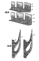
- FIGs. 1A and 1B there is shown an artists conception of a vortex structure that results from the flow of hot gases over a turbine blade having no fillet (i.e. with the blade portion intersecting with the platform section at substantially an orthogonal angle).
- a vortex structure that results from the flow of hot gases over a turbine blade having no fillet (i.e. with the blade portion intersecting with the platform section at substantially an orthogonal angle).
- secondary flow vortices are formed such that hot gases can be trapped on the suction side of the airfoils as shown and these can then result in severe distress in these regions.
- Fig. 2 there is shown a computational fluid dyn amics simulation of the streamlines of gases passing around an airfoil having little or no fillet as discussed hereinabove.
- Fig. 2 there is evidence of secondary flow vortices that tend to affect the thermal load to the airfoil.
- the airfoil was modified to include a leading edge fillet with a substantial radius.
- present blade design configurations use leading edge fillets to the blade platforms with a radius, or offset, in the range of 0.080 inches (2.03 mm) or less.
- a fillet is provided having a radius that may be as high as a quarter of the size of the entire radial span or about 3/8 inches (9.5 mm) or higher. This modification has been found to improve the flow characteristics of the airfoil and to thereby substantially reduce the temperatures in the fillet region. For example, in Fig.
- 3A there is shown a color code indication of temperatures in three gradations, A, B and C for both an airfoil with no fillet (at the bottom) and one with a large fillet (at the top).
- the cooler range of temperatures is shown by the darker colors A at the bottom and the hotter temperature ranges are shown by the lighter colors C at the top.
- the gas temperatures flowing over the modified airfoil i.e. with a fillet
- Fig. 3B wherein there is shown a comparison of adiabatic wall temperatures between an airfoil having no fillet (as shown at the left) and one with the fillet (as shown at the right).
- the darker portion D is indication of cooler temperature range and the lighter portion E is indicative of a higher temperature range.
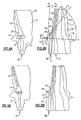
- a turbine blade 11 is shown in a front view and a side view, respectively, the turbine blade 11 has a fir tree 12 for attaching the blade 11 to a rotating member such as a disk, an airfoil portion 13 and a platform 14 having a leading edge 15 and a trailing edge 20 that define a plane x-x.
- the airfoil portion 13 has a pressure side (i.e. concave side) and a suction side (i.e. convex side), a leading edge 16 that defines a plane Y 1 -Y 1 that is substantially orthogonal to plane x-x and a trailing edge 17.
- the large fillet 18 is defined by the parameters D and ⁇ with the offset D being in the range of 0.080" to 0.375" (2.03 to 9.53 mm) and the fillet angle ⁇ being in the range of 10° to 60°. It is this large radius fillet that overcomes the problems of end wall vortices as discussed hereinabove.
- a leading edge cavity 19 there is provided behind the leading edge wall a leading edge cavity 19, and parallel to that is a coolant supply cavity 21.
- the coolant supply cavity 21 is supplied with a source of cooling air that flows up through the radial passage 22 which passes through the fir tree 12.
- the coolant supply cavity 21 is fluidly connected to the leading edge cavity 19 by a plurality of impingement cooling passages 23. These impingement cooling passages 23 are formed during the casting process by the insertion of small ceramic core rods which are subsequently removed to leave the impingement cooling passages 23. Thus, the cooling air passes through the radial passage 22 and into the coolant supply cavity 21.
- the leading edge cavity 19 extends downwardly toward the platform 14 into an expanded fillet cavity 24 directly behind the fillet 18.
- a dedicated fillet feed passage 26 that extends radially up through the fir tree 12 as shown.
- the fillet feed passage 26 is fluidly connected to the fillet cavity 24 by a cross-over openings 27.
- cooling air is introduced into the fillet feed passage 26, passes through the cross-over openings 27 and into the fillet cavity 24 to cool the fillet 18 prior to being discharged through film holes (not shown).
- impingement cooling passages 23 have been circular in cross sectional form. We have found that if these passages are elongated in the radial direction to a racetrack form as shown in Fig. 6B, better target wall coverage will be obtained as the cooling air passes through these passages to flow into the leading edge cavity 19.
- FIG. 5A and 5B an alternate embodiment is shown to again include a dedicated fillet feed passage 26 extending radially up through the fir tree 12 and through a cross-over opening 27.
- the cross-over opening 27 interconnects with a fillet cavity 24.
- the coolant flow is directed to impinge at the base of the fillet area and flow upwards over a series of cooling features, such as hemispherical dimples before exiting by way of leading edge film holes.
- Fig. 7 Such a design is shown in Fig. 7 wherein a plurality of dimples 29 are formed on the inner surface 31 of the airfoil leading edge 16 as shown. These dimples provide for an enhanced cooling effect of the leading edge in the fillet region.
- FIG. 8A and 8B An alternative embodiment of the present invention is shown in Fig. 8A and 8B wherein, rather than the ceramic core which ties the supply and leading edge cores as discussed hereinabove with respect to the Figs. 4A and 4B embodiment, the supply and leading edge cores are connected with a refractory metal core (RMC) 32.
- RMC refractory metal core
- FIG. 10 Another feature to enhance cooling characteristics is shown in Fig. 10.
- the common approach for the placement of the impingement cooling passages is mid-way, or on the mid-plane 33, between the suction side 34 and the pressure side 36 of the blade 11.
- the impingement cooling passages 28 are off-set towards the pressure side 36 as shown. This results in improved cooling by taking advantage of the Coriolis forces that result from rotation of the blade.
- trip strips in a flow passage is a common way to enhance the flow and cooling characteristics in an airfoil.
- a pair of such trip strips 37 are shown in Fig. 11A and 11B as applied to the fillet feed passage 26.
- the cross-over opening 27 can be critical in preventing the interference that the trip strips may have on the flow to the cross-over opening 27.
- the cross-over opening 27 is preferably placed in a position substantially intermediate between a pair of adjacent trip strips 37 as shown. This same concept is equally applicable to the placement of the impingement cooling passages 28 with respect to trip strips that may be placed in the coolant supply cavity 21.
- both the radial feed passage 22 and the fillet feed passage 26 has a bell shaped inlet as shown at 38 and 39, respectively. These bell shaped inlet openings have been found to decrease the resistance and the pressure losses of the airflow into the passages and thereby increase the amount of cooling effect that can be obtained.
- the typical spacing between film holes (i.e. the pitch between the center of adj acent holes) on the principal portion of the blade is in the area of two times the diameter of the film holes, whereas the spacing of the film holes 41 along the fillet are preferably in the range of one-and-one half times the diameter of the film holes.
- Figs. 14A-14B there is shown an alternative embodiment of the film cooling holes at the leading edge of the blade and of the fillets.
- a trench 42 is formed in the leading edge 16 and extends down to and transitions into the fillet 18 as shown.
- a plurality of film holes 43 then interconnects the inner surface 31 of the leading edge 16 to the trench 42 as shown.
- the film holes 43 are formed with a cross sectional shape that is a racetrack shape rather than a round shape as discussed hereinabove.
- the affect of the trench is to allow the cooling air to pass through the film holes and fill the trench before spilling over onto the surface of the leading edge 16.
- a further modification of the film holes can be made such that their shape, when extending from the inner surface 31 to the leading edge 16, includes a metering portion 44 and a diffusion portion 46.
- the metering potion 44 is preferably cylindrical or racetrack in cross-sectional form, and the diffusion portion 46 is conically shaped as shown to enhance the cooling effect of the cooling air flowing therethrough. The diffusion portion 46 will then discharge its cooling air to the trench 42 as described hereinabove.
- angles of these portions may, of course, be varied to meet the requirement of the particular application. Typical values may be, for example, an angle ⁇ of 20° and an angle ⁇ of 14°.
Landscapes
- Engineering & Computer Science (AREA)
- Mechanical Engineering (AREA)
- General Engineering & Computer Science (AREA)
- Chemical & Material Sciences (AREA)
- Combustion & Propulsion (AREA)
- Physics & Mathematics (AREA)
- Fluid Mechanics (AREA)
- Turbine Rotor Nozzle Sealing (AREA)
Applications Claiming Priority (1)
| Application Number | Priority Date | Filing Date | Title |
|---|---|---|---|
| US10/967,558 US7217094B2 (en) | 2004-10-18 | 2004-10-18 | Airfoil with large fillet and micro-circuit cooling |
Publications (2)
| Publication Number | Publication Date |
|---|---|
| EP1657403A1 true EP1657403A1 (fr) | 2006-05-17 |
| EP1657403B1 EP1657403B1 (fr) | 2008-12-24 |
Family
ID=35830711
Family Applications (1)
| Application Number | Title | Priority Date | Filing Date |
|---|---|---|---|
| EP05256378A Expired - Lifetime EP1657403B1 (fr) | 2004-10-18 | 2005-10-13 | Aube avec arrondis large et avec circuit de refroidissement comprennant des microcanaux |
Country Status (8)
| Country | Link |
|---|---|
| US (1) | US7217094B2 (fr) |
| EP (1) | EP1657403B1 (fr) |
| JP (1) | JP2006112429A (fr) |
| KR (1) | KR20060051506A (fr) |
| CN (1) | CN1763353A (fr) |
| DE (1) | DE602005011918D1 (fr) |
| SG (1) | SG121987A1 (fr) |
| TW (1) | TWI280315B (fr) |
Families Citing this family (32)
| Publication number | Priority date | Publication date | Assignee | Title |
|---|---|---|---|---|
| US7581927B2 (en) * | 2006-07-28 | 2009-09-01 | United Technologies Corporation | Serpentine microcircuit cooling with pressure side features |
| US7841828B2 (en) * | 2006-10-05 | 2010-11-30 | Siemens Energy, Inc. | Turbine airfoil with submerged endwall cooling channel |
| US8757974B2 (en) † | 2007-01-11 | 2014-06-24 | United Technologies Corporation | Cooling circuit flow path for a turbine section airfoil |
| US8157527B2 (en) * | 2008-07-03 | 2012-04-17 | United Technologies Corporation | Airfoil with tapered radial cooling passage |
| US8348614B2 (en) * | 2008-07-14 | 2013-01-08 | United Technologies Corporation | Coolable airfoil trailing edge passage |
| US8167557B2 (en) * | 2008-08-07 | 2012-05-01 | Honeywell International Inc. | Gas turbine engine assemblies with vortex suppression and cooling film replenishment |
| US8572844B2 (en) * | 2008-08-29 | 2013-11-05 | United Technologies Corporation | Airfoil with leading edge cooling passage |
| US8303252B2 (en) * | 2008-10-16 | 2012-11-06 | United Technologies Corporation | Airfoil with cooling passage providing variable heat transfer rate |
| GB2465337B (en) * | 2008-11-12 | 2012-01-11 | Rolls Royce Plc | A cooling arrangement |
| EP2196625A1 (fr) * | 2008-12-10 | 2010-06-16 | Siemens Aktiengesellschaft | Aube de turbine dotée d'un passage agencé dans une paroi de séparation et noyau de coulage associé |
| US8109725B2 (en) * | 2008-12-15 | 2012-02-07 | United Technologies Corporation | Airfoil with wrapped leading edge cooling passage |
| US20100284800A1 (en) * | 2009-05-11 | 2010-11-11 | General Electric Company | Turbine nozzle with sidewall cooling plenum |
| US20110097188A1 (en) * | 2009-10-23 | 2011-04-28 | General Electric Company | Structure and method for improving film cooling using shallow trench with holes oriented along length of trench |
| KR101303831B1 (ko) * | 2010-09-29 | 2013-09-04 | 한국전력공사 | 터빈 블레이드 |
| US20120163993A1 (en) * | 2010-12-23 | 2012-06-28 | United Technologies Corporation | Leading edge airfoil-to-platform fillet cooling tube |
| WO2012124215A1 (fr) | 2011-03-11 | 2012-09-20 | 三菱重工業株式会社 | Aube de rotor de turbine à gaz et turbine à gaz |
| US9909425B2 (en) | 2011-10-31 | 2018-03-06 | Pratt & Whitney Canada Corporation | Blade for a gas turbine engine |
| WO2014120565A1 (fr) * | 2013-02-04 | 2014-08-07 | United Technologies Corporation | Admission évasée pour pale de turbine |
| WO2014197061A2 (fr) | 2013-03-15 | 2014-12-11 | United Technologies Corporation | Trou de refroidissement de film formé de turbine à gaz |
| EP3011155B1 (fr) | 2013-06-19 | 2020-12-30 | United Technologies Corporation | Bouclier thermique |
| US10352180B2 (en) | 2013-10-23 | 2019-07-16 | General Electric Company | Gas turbine nozzle trailing edge fillet |
| US10329921B2 (en) | 2014-10-24 | 2019-06-25 | United Technologies Corporation | Cooling configuration for a component |
| US10247011B2 (en) | 2014-12-15 | 2019-04-02 | United Technologies Corporation | Gas turbine engine component with increased cooling capacity |
| US10612392B2 (en) | 2014-12-18 | 2020-04-07 | United Technologies Corporation | Gas turbine engine component with conformal fillet cooling path |
| US9920633B2 (en) * | 2015-03-02 | 2018-03-20 | United Technologies Corporation | Compound fillet for a gas turbine airfoil |
| US10539026B2 (en) | 2017-09-21 | 2020-01-21 | United Technologies Corporation | Gas turbine engine component with cooling holes having variable roughness |
| JP6943706B2 (ja) * | 2017-09-22 | 2021-10-06 | 三菱パワー株式会社 | タービン翼及びガスタービン |
| EP3564483A1 (fr) * | 2018-05-04 | 2019-11-06 | Siemens Aktiengesellschaft | Pale d'aube pour une aube de turbine |
| US10907479B2 (en) | 2018-05-07 | 2021-02-02 | Raytheon Technologies Corporation | Airfoil having improved leading edge cooling scheme and damage resistance |
| US10941663B2 (en) | 2018-05-07 | 2021-03-09 | Raytheon Technologies Corporation | Airfoil having improved leading edge cooling scheme and damage resistance |
| EP3927220B1 (fr) * | 2019-02-20 | 2022-06-29 | Koninklijke Philips N.V. | Tube plongeur pour séparateur cyclonique |
| CN114893254A (zh) * | 2022-04-22 | 2022-08-12 | 中国联合重型燃气轮机技术有限公司 | 发动机叶片和燃气轮机 |
Citations (8)
| Publication number | Priority date | Publication date | Assignee | Title |
|---|---|---|---|---|
| GB872705A (en) * | 1959-01-22 | 1961-07-12 | Gen Motors Corp | Improvements in cast turbine blades and the manufacture thereof |
| US4515526A (en) * | 1981-12-28 | 1985-05-07 | United Technologies Corporation | Coolable airfoil for a rotary machine |
| US5382133A (en) * | 1993-10-15 | 1995-01-17 | United Technologies Corporation | High coverage shaped diffuser film hole for thin walls |
| EP1013877A2 (fr) * | 1998-12-21 | 2000-06-28 | United Technologies Corporation | Aube de turbine creuse |
| EP1128024A2 (fr) * | 2000-02-23 | 2001-08-29 | Mitsubishi Heavy Industries, Ltd. | Aube mobile pour turbines à gaz |
| US6406260B1 (en) * | 1999-10-22 | 2002-06-18 | Pratt & Whitney Canada Corp. | Heat transfer promotion structure for internally convectively cooled airfoils |
| EP1262631A2 (fr) * | 2001-05-21 | 2002-12-04 | United Technologies Corporation | Aube de turbine refroidie par couche d'air |
| US20030108423A1 (en) * | 2001-12-12 | 2003-06-12 | Morgan Clive A. | Airfoil for a turbine nozzle of a gas turbine engine and method of making same |
Family Cites Families (4)
| Publication number | Priority date | Publication date | Assignee | Title |
|---|---|---|---|---|
| US5975851A (en) * | 1997-12-17 | 1999-11-02 | United Technologies Corporation | Turbine blade with trailing edge root section cooling |
| US6290463B1 (en) * | 1999-09-30 | 2001-09-18 | General Electric Company | Slotted impingement cooling of airfoil leading edge |
| DE10332563A1 (de) * | 2003-07-11 | 2005-01-27 | Rolls-Royce Deutschland Ltd & Co Kg | Turbinenschaufel mit Prallkühlung |
| US20050265840A1 (en) * | 2004-05-27 | 2005-12-01 | Levine Jeffrey R | Cooled rotor blade with leading edge impingement cooling |
-
2004
- 2004-10-18 US US10/967,558 patent/US7217094B2/en not_active Expired - Lifetime
-
2005
- 2005-08-29 TW TW094129524A patent/TWI280315B/zh not_active IP Right Cessation
- 2005-09-22 KR KR1020050087912A patent/KR20060051506A/ko not_active Withdrawn
- 2005-10-11 SG SG200506651A patent/SG121987A1/en unknown
- 2005-10-13 DE DE602005011918T patent/DE602005011918D1/de not_active Expired - Lifetime
- 2005-10-13 EP EP05256378A patent/EP1657403B1/fr not_active Expired - Lifetime
- 2005-10-14 JP JP2005299490A patent/JP2006112429A/ja active Pending
- 2005-10-18 CN CNA2005101164739A patent/CN1763353A/zh active Pending
Patent Citations (8)
| Publication number | Priority date | Publication date | Assignee | Title |
|---|---|---|---|---|
| GB872705A (en) * | 1959-01-22 | 1961-07-12 | Gen Motors Corp | Improvements in cast turbine blades and the manufacture thereof |
| US4515526A (en) * | 1981-12-28 | 1985-05-07 | United Technologies Corporation | Coolable airfoil for a rotary machine |
| US5382133A (en) * | 1993-10-15 | 1995-01-17 | United Technologies Corporation | High coverage shaped diffuser film hole for thin walls |
| EP1013877A2 (fr) * | 1998-12-21 | 2000-06-28 | United Technologies Corporation | Aube de turbine creuse |
| US6406260B1 (en) * | 1999-10-22 | 2002-06-18 | Pratt & Whitney Canada Corp. | Heat transfer promotion structure for internally convectively cooled airfoils |
| EP1128024A2 (fr) * | 2000-02-23 | 2001-08-29 | Mitsubishi Heavy Industries, Ltd. | Aube mobile pour turbines à gaz |
| EP1262631A2 (fr) * | 2001-05-21 | 2002-12-04 | United Technologies Corporation | Aube de turbine refroidie par couche d'air |
| US20030108423A1 (en) * | 2001-12-12 | 2003-06-12 | Morgan Clive A. | Airfoil for a turbine nozzle of a gas turbine engine and method of making same |
Also Published As
| Publication number | Publication date |
|---|---|
| JP2006112429A (ja) | 2006-04-27 |
| EP1657403B1 (fr) | 2008-12-24 |
| CN1763353A (zh) | 2006-04-26 |
| SG121987A1 (en) | 2006-05-26 |
| TWI280315B (en) | 2007-05-01 |
| DE602005011918D1 (de) | 2009-02-05 |
| US7217094B2 (en) | 2007-05-15 |
| TW200626787A (en) | 2006-08-01 |
| KR20060051506A (ko) | 2006-05-19 |
| US20060083614A1 (en) | 2006-04-20 |
Similar Documents
| Publication | Publication Date | Title |
|---|---|---|
| EP1657403B1 (fr) | Aube avec arrondis large et avec circuit de refroidissement comprennant des microcanaux | |
| US7220103B2 (en) | Impingement cooling of large fillet of an airfoil | |
| US6602052B2 (en) | Airfoil tip squealer cooling construction | |
| US4515523A (en) | Cooling arrangement for airfoil stator vane trailing edge | |
| US7997868B1 (en) | Film cooling hole for turbine airfoil | |
| CN101535602B (zh) | 涡轮叶片 | |
| EP2233693A1 (fr) | Structure de refroidissement d'aube de turbine | |
| CN1920258B (zh) | 具有倾斜端孔的涡轮叶片 | |
| US7351036B2 (en) | Turbine airfoil cooling system with elbowed, diffusion film cooling hole | |
| JP5905631B1 (ja) | 動翼、これを備えているガスタービン、及び動翼の製造方法 | |
| US8727725B1 (en) | Turbine vane with leading edge fillet region cooling | |
| US7270515B2 (en) | Turbine airfoil trailing edge cooling system with segmented impingement ribs | |
| EP1128024A2 (fr) | Aube mobile pour turbines à gaz | |
| US9039371B2 (en) | Trailing edge cooling using angled impingement on surface enhanced with cast chevron arrangements | |
| KR20000070801A (ko) | 가스 터빈 에어포일을 냉각하는 장치 및 그 제조 방법 | |
| CN101550843A (zh) | 燃气轮机翼型 | |
| CN102089498A (zh) | 用于燃气涡轮机的涡轮机叶片和用于制造这样的涡轮机叶片的型芯 | |
| JPH112101A (ja) | ガスタービン冷却動翼 | |
| JPS62165503A (ja) | 長手方向に延在する中空エ−ロフオイルの製造方法 | |
| JP2010502872A (ja) | 冷却形タービン動翼 | |
| JP2007146841A (ja) | タービンエンジンの構成部品内に使用される冷却マイクロ回路およびタービンブレード | |
| JP2020507707A (ja) | ガスタービン用のタービンブレードまたはタービンベーン | |
| CN111485956A (zh) | 涡轮导向冷却叶片 | |
| CA2513036C (fr) | Canal de refroidissement de profil aerodynamique avec restriction d'ecoulement au bord de fuite |
Legal Events
| Date | Code | Title | Description |
|---|---|---|---|
| PUAI | Public reference made under article 153(3) epc to a published international application that has entered the european phase |
Free format text: ORIGINAL CODE: 0009012 |
|
| AK | Designated contracting states |
Kind code of ref document: A1 Designated state(s): AT BE BG CH CY CZ DE DK EE ES FI FR GB GR HU IE IS IT LI LT LU LV MC NL PL PT RO SE SI SK TR |
|
| AX | Request for extension of the european patent |
Extension state: AL BA HR MK YU |
|
| 17P | Request for examination filed |
Effective date: 20061019 |
|
| 17Q | First examination report despatched |
Effective date: 20061120 |
|
| AKX | Designation fees paid |
Designated state(s): DE FR GB IT |
|
| GRAP | Despatch of communication of intention to grant a patent |
Free format text: ORIGINAL CODE: EPIDOSNIGR1 |
|
| GRAS | Grant fee paid |
Free format text: ORIGINAL CODE: EPIDOSNIGR3 |
|
| GRAA | (expected) grant |
Free format text: ORIGINAL CODE: 0009210 |
|
| AK | Designated contracting states |
Kind code of ref document: B1 Designated state(s): DE FR GB IT |
|
| REG | Reference to a national code |
Ref country code: GB Ref legal event code: FG4D |
|
| REF | Corresponds to: |
Ref document number: 602005011918 Country of ref document: DE Date of ref document: 20090205 Kind code of ref document: P |
|
| PLBE | No opposition filed within time limit |
Free format text: ORIGINAL CODE: 0009261 |
|
| STAA | Information on the status of an ep patent application or granted ep patent |
Free format text: STATUS: NO OPPOSITION FILED WITHIN TIME LIMIT |
|
| 26N | No opposition filed |
Effective date: 20090925 |
|
| REG | Reference to a national code |
Ref country code: FR Ref legal event code: ST Effective date: 20100630 |
|
| PG25 | Lapsed in a contracting state [announced via postgrant information from national office to epo] |
Ref country code: FR Free format text: LAPSE BECAUSE OF NON-PAYMENT OF DUE FEES Effective date: 20091102 |
|
| PG25 | Lapsed in a contracting state [announced via postgrant information from national office to epo] |
Ref country code: IT Free format text: LAPSE BECAUSE OF FAILURE TO SUBMIT A TRANSLATION OF THE DESCRIPTION OR TO PAY THE FEE WITHIN THE PRESCRIBED TIME-LIMIT Effective date: 20081224 |
|
| REG | Reference to a national code |
Ref country code: DE Ref legal event code: R082 Ref document number: 602005011918 Country of ref document: DE Representative=s name: SCHMITT-NILSON SCHRAUD WAIBEL WOHLFROM PATENTA, DE |
|
| REG | Reference to a national code |
Ref country code: DE Ref legal event code: R082 Ref document number: 602005011918 Country of ref document: DE Representative=s name: SCHMITT-NILSON SCHRAUD WAIBEL WOHLFROM PATENTA, DE Ref country code: DE Ref legal event code: R081 Ref document number: 602005011918 Country of ref document: DE Owner name: UNITED TECHNOLOGIES CORP. (N.D.GES.D. STAATES , US Free format text: FORMER OWNER: UNITED TECHNOLOGIES CORP., HARTFORD, CONN., US |
|
| PGFP | Annual fee paid to national office [announced via postgrant information from national office to epo] |
Ref country code: DE Payment date: 20190918 Year of fee payment: 15 |
|
| REG | Reference to a national code |
Ref country code: DE Ref legal event code: R119 Ref document number: 602005011918 Country of ref document: DE |
|
| PG25 | Lapsed in a contracting state [announced via postgrant information from national office to epo] |
Ref country code: DE Free format text: LAPSE BECAUSE OF NON-PAYMENT OF DUE FEES Effective date: 20210501 |
|
| PGFP | Annual fee paid to national office [announced via postgrant information from national office to epo] |
Ref country code: GB Payment date: 20240919 Year of fee payment: 20 |
|
| REG | Reference to a national code |
Ref country code: GB Ref legal event code: PE20 Expiry date: 20251012 |