EP1657480B1 - Verbesserungen betreffend Rohrverbindungen - Google Patents
Verbesserungen betreffend Rohrverbindungen Download PDFInfo
- Publication number
- EP1657480B1 EP1657480B1 EP06003755A EP06003755A EP1657480B1 EP 1657480 B1 EP1657480 B1 EP 1657480B1 EP 06003755 A EP06003755 A EP 06003755A EP 06003755 A EP06003755 A EP 06003755A EP 1657480 B1 EP1657480 B1 EP 1657480B1
- Authority
- EP
- European Patent Office
- Prior art keywords
- cap
- coupling body
- tube
- coupling
- diaphragm
- Prior art date
- Legal status (The legal status is an assumption and is not a legal conclusion. Google has not performed a legal analysis and makes no representation as to the accuracy of the status listed.)
- Expired - Lifetime
Links
- 230000008878 coupling Effects 0.000 title claims description 131
- 238000010168 coupling process Methods 0.000 title claims description 131
- 238000005859 coupling reaction Methods 0.000 title claims description 131
- 230000000994 depressogenic effect Effects 0.000 claims description 9
- 125000006850 spacer group Chemical group 0.000 claims description 7
- 230000000881 depressing effect Effects 0.000 claims description 5
- 238000007789 sealing Methods 0.000 claims description 4
- 230000006835 compression Effects 0.000 description 3
- 238000007906 compression Methods 0.000 description 3
- 230000004048 modification Effects 0.000 description 2
- 238000012986 modification Methods 0.000 description 2
- 238000010276 construction Methods 0.000 description 1
- 238000003780 insertion Methods 0.000 description 1
- 230000037431 insertion Effects 0.000 description 1
- 238000004519 manufacturing process Methods 0.000 description 1
- 239000002184 metal Substances 0.000 description 1
- 239000002991 molded plastic Substances 0.000 description 1
- 239000004033 plastic Substances 0.000 description 1
- 229920003023 plastic Polymers 0.000 description 1
- 230000002040 relaxant effect Effects 0.000 description 1
- 230000000717 retained effect Effects 0.000 description 1
Images


Classifications
-
- F—MECHANICAL ENGINEERING; LIGHTING; HEATING; WEAPONS; BLASTING
- F16—ENGINEERING ELEMENTS AND UNITS; GENERAL MEASURES FOR PRODUCING AND MAINTAINING EFFECTIVE FUNCTIONING OF MACHINES OR INSTALLATIONS; THERMAL INSULATION IN GENERAL
- F16L—PIPES; JOINTS OR FITTINGS FOR PIPES; SUPPORTS FOR PIPES, CABLES OR PROTECTIVE TUBING; MEANS FOR THERMAL INSULATION IN GENERAL
- F16L19/00—Joints in which sealing surfaces are pressed together by means of a member, e.g. a swivel nut, screwed on, or into, one of the joint parts
- F16L19/005—Joints in which sealing surfaces are pressed together by means of a member, e.g. a swivel nut, screwed on, or into, one of the joint parts comprising locking means for the threaded member
-
- F—MECHANICAL ENGINEERING; LIGHTING; HEATING; WEAPONS; BLASTING
- F16—ENGINEERING ELEMENTS AND UNITS; GENERAL MEASURES FOR PRODUCING AND MAINTAINING EFFECTIVE FUNCTIONING OF MACHINES OR INSTALLATIONS; THERMAL INSULATION IN GENERAL
- F16L—PIPES; JOINTS OR FITTINGS FOR PIPES; SUPPORTS FOR PIPES, CABLES OR PROTECTIVE TUBING; MEANS FOR THERMAL INSULATION IN GENERAL
- F16L19/00—Joints in which sealing surfaces are pressed together by means of a member, e.g. a swivel nut, screwed on, or into, one of the joint parts
- F16L19/08—Joints in which sealing surfaces are pressed together by means of a member, e.g. a swivel nut, screwed on, or into, one of the joint parts with metal rings which bite into the wall of the pipe
- F16L19/083—Joints in which sealing surfaces are pressed together by means of a member, e.g. a swivel nut, screwed on, or into, one of the joint parts with metal rings which bite into the wall of the pipe the longitudinal cross-section of the ring not being modified during clamping
- F16L19/086—Joints in which sealing surfaces are pressed together by means of a member, e.g. a swivel nut, screwed on, or into, one of the joint parts with metal rings which bite into the wall of the pipe the longitudinal cross-section of the ring not being modified during clamping with additional sealing means
-
- F—MECHANICAL ENGINEERING; LIGHTING; HEATING; WEAPONS; BLASTING
- F16—ENGINEERING ELEMENTS AND UNITS; GENERAL MEASURES FOR PRODUCING AND MAINTAINING EFFECTIVE FUNCTIONING OF MACHINES OR INSTALLATIONS; THERMAL INSULATION IN GENERAL
- F16L—PIPES; JOINTS OR FITTINGS FOR PIPES; SUPPORTS FOR PIPES, CABLES OR PROTECTIVE TUBING; MEANS FOR THERMAL INSULATION IN GENERAL
- F16L37/00—Couplings of the quick-acting type
- F16L37/08—Couplings of the quick-acting type in which the connection between abutting or axially overlapping ends is maintained by locking members
- F16L37/084—Couplings of the quick-acting type in which the connection between abutting or axially overlapping ends is maintained by locking members combined with automatic locking
- F16L37/092—Couplings of the quick-acting type in which the connection between abutting or axially overlapping ends is maintained by locking members combined with automatic locking by means of elements wedged between the pipe and the frusto-conical surface of the body of the connector
- F16L37/0925—Couplings of the quick-acting type in which the connection between abutting or axially overlapping ends is maintained by locking members combined with automatic locking by means of elements wedged between the pipe and the frusto-conical surface of the body of the connector with rings which bite into the wall of the pipe
-
- F—MECHANICAL ENGINEERING; LIGHTING; HEATING; WEAPONS; BLASTING
- F16—ENGINEERING ELEMENTS AND UNITS; GENERAL MEASURES FOR PRODUCING AND MAINTAINING EFFECTIVE FUNCTIONING OF MACHINES OR INSTALLATIONS; THERMAL INSULATION IN GENERAL
- F16L—PIPES; JOINTS OR FITTINGS FOR PIPES; SUPPORTS FOR PIPES, CABLES OR PROTECTIVE TUBING; MEANS FOR THERMAL INSULATION IN GENERAL
- F16L37/00—Couplings of the quick-acting type
- F16L37/08—Couplings of the quick-acting type in which the connection between abutting or axially overlapping ends is maintained by locking members
- F16L37/084—Couplings of the quick-acting type in which the connection between abutting or axially overlapping ends is maintained by locking members combined with automatic locking
- F16L37/092—Couplings of the quick-acting type in which the connection between abutting or axially overlapping ends is maintained by locking members combined with automatic locking by means of elements wedged between the pipe and the frusto-conical surface of the body of the connector
- F16L37/0927—Couplings of the quick-acting type in which the connection between abutting or axially overlapping ends is maintained by locking members combined with automatic locking by means of elements wedged between the pipe and the frusto-conical surface of the body of the connector the wedge element being axially displaceable for releasing the coupling
Definitions
- UK-A-1520742 discloses a "Speedfit" connector comprising a coupling body with a throughway open at one end and a tapered cam surface in the open end to receive a collet for.locking a tube in the coupling.
- the collet is compressed against the tube by a slight withdrawal of the tube/collet from the coupling body which locks the tube in the coupling body.
- the collet can be depressed into the body to release the tube when required.
- UK-A-2167147 discloses a "SuperSeal” connector which is a modification of the "Speedfit” connector and has a separate sleeve screwed into the open end of the coupling body in which the tapered cam is formed. By screwing the sleeve into the coupling body the gripping action of the collet on the tube is increased. Also the collet becomes locked up in the coupling body and cannot be depressed to release the tube. The tube is then permanently locked in the coupling body.
- EP-A-0945662 discloses a tube coupling having both "Speedfit” and SuperSeal" modes of operation. More particularly the coupling comprises a coupling body having a throughway open at one end to receive an end portion of a tube and having an internal cam surface tapering towards the open end in which a collet is located for locking the tube in the coupling body by engagement with the tapered cam surface and having stop means to limit entry of the collet into the throughway.
- the coupling body has a main portion, the throughway of which receives the end of the tube and contains said stop means to limit insertion of the collet and an end cap in screw threaded engagement with the main body. The end cap provides said open end to the throughway and the tapered cam surface.
- Indexing means are provided between the end cap and the main body to define different positions of rotation of adjustment in the first of which the tube can be inserted in and by depressing the collet into the coupling body, released in the coupling body (i.e. "Speedfit” mode) and in the second of which the collet is engaged with the stop means to prevent the collet being depressed into the coupling body to release the tube (i.e. "SuperSeal” mode).
- EP-A-1233225 discloses a tube coupling to receive and hold a tube comprising a coupling body having a throughway open at one end to receive a tube. An annular step is formed in the throughway facing the open end to receive an end of the tube. An end cap is screwed onto the coupling body for movement between forward and retracted positions on the coupling body. The end cap has an opening for the tube to extend through.
- a seal is located in the coupling body between the step and the open end of the body in the form of an annular sleeve encircling the throughway. The seal has an out turned annular flange at one end which engages with the annular step to receive and seal with an end of the tube inserted into the throughway.
- a compression device in the throughway is operable to compress the sleeve around the outer surface of the tube adjacent the end of the tube to form a seal with the end of the seal.
- a collet is located in the end cap to receive and grip a tube to hold the tube in the coupling body. The retracted position of the cap allows the tube to be inserted through the collet into engagement with the flange at the end of the seal and to be released from the coupling body by depressing the collet into the coupling body. In the forward position of the cap, the collet engages the compression device acting on the seal and is prevented from being depressed into the coupling body to release the tube from the coupling body.
- the arrangement thus provides the "Speedfit” and "Superseal" functions of the tube coupling referred to above.
- This invention provides a tube coupling comprising a coupling body having a throughway open at one end to receive a tube, an end cap in screw-threaded engagement with the coupling body to move between initial and advanced positions along the coupling body and having an opening for the tube and an internal cam surface tapering towards the tube opening, a collet in the end cap engaging the cam surface to lock a tube in the cap with movement of the collet outwardly of the cap and to release the tube when depressed inwardly of the cap, and stop means in the coupling body to limit movement of the collet inwardly of the end cap, the initial position of the said end cap on the coupling body allowing a tube to be inserted and locked in the end cap by the collet and to be released by depressing the collet inwardly of the cap and the advanced position of the end cap holding the collet adjacent the stop means in the coupling body to prevent release of the tube; wherein the coupling body has an external screw-threaded portion extending along the coupling body from said one
- the body has a thin, flexible, flange or "diaphragm" protruding radially from the body's outside diameter and the cap has an internal slot, similar to a circlip groove.
- the cap As the cap is assembled onto the body the cap butts against the diaphragm and bends away as the cap passes beyond. Thereafter, the diaphragm snaps into the groove but due to the groove's major diameter cannot flex back to its original position - it is always bent in the direction opposing any removal of the cap from the body.
- the diaphragm is snap engaged in the slot with longitudinal movement of the cap along the body.
- the cap's position is constrained lengthwise by the end of the cap butting against the large inflexible flange on the body or by the flexible diaphragm opposing and butting against the end of the groove in the cap.
- the detent means provides an increasing resistance to movement of the cap along the coupling body from the advanced position towards the initial position and preventing movement beyond the initial position so that the cap is retained on the coupling body.
- the mouth of the cap may be formed with an inturned lip providing a restricted opening of smaller diameter than the outer diameter of the diaphragm, and with an annular slot encircling the inner side of the cap inwardly of the lip into which the annular diaphragm can snap after being deformed as it passes through the annular lip in the mouth of the cap to define said initial position of the cap on the coupling body and to hold the diaphragm in a deformed state in engagement with the bottom of the slot to resist withdrawal of the cap from the coupling body.
- the annular slot may taper outwardly away from the lip into the cap so that as the cap is advanced along the coupling body past the diaphragm, the diaphragm can slide along and expand into the deepening part of the slot to reduce the deformity imposed on the diaphragm.
- the slot in the cap at its deeper end may have an extended deeper slot into which the diaphragm can extend in the advanced position of the cap on the coupling body, the additional slot being sufficiently deep to accommodate the diaphragm without deformation.
- the diaphragm may be a single continuous diaphragm encircling the coupling body or may comprise a series of segments extending around the coupling body.
- the aforesaid insert ring may be a split ring mounted in a groove in the coupling body.
- the coupling body may be formed with an external upstanding annular abutment located beyond the diaphragm from the screw-thread on the coupling body to provide an end stop for restricting the extent to which the cap can be screwed onto the coupling body to define said advanced position in which the cap can be screwed to lock a tube in the collet.
- the stop means in the coupling body to restrict movement of the collet when depressed into the coupling body may comprise a sealing arrangement located in the coupling body for a tube.
- the sealing arrangement may comprise a spacer ring encircling the throughway in the coupling body and an O ring seal located between the spacer ring and a shoulder formed in the throughway, the inner end of the collet being engageable with the spacer ring to restrict entry of the collet into the coupling body.
- FIG. 1 of the drawings there is shown a moulded plastics tube coupling indicated generally by reference numeral 10 having a throughway 11 open at one end 12 to receive an end portion of a tube 13.
- the coupling comprises a main body 10a and an end cap 10b screwed onto the main body as described below.
- the throughway in the main body has a first increase in diameter at a step 14 to provide an enlarged bore 15 in which the end of the tube 13 is a close sliding fit with the end of the tube engaging the step 14.
- the throughway has a further increase in diameter at a step 16 to form a further enlarged bore 17 in which an 'O' ring seal 18 is located against the step followed by a spacer washer or compression ring 19.
- the main body 10a has an external screw-threaded section 20 extending from one end of the body followed by a reduced diameter plain section 21 in which a detent is formed as described later and followed in turn by an integral encircling radial flange 22.
- the flange 22 has an abutment face 23 to provide an end stop for the cap when the latter is fully screwed onto the coupling body as described below.
- the end cap 10b of the coupling body encircles the main body and has an internal feature for engaging with the detent on the main body portion again as described later.
- a collet indicated at 25 is mounted in the open end of the coupling body comprising an annular member 26 and resilient arms 27 projecting from the annular member into the throughway of the coupling body and terminating in heads 28.
- the heads of the collet engage in a tapered cam surface 29 converging towards the end of the coupling body to be compressed against the tube 13 by engagement of the heads with the cam surface to lock the tube in the coupling body.
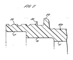
- FIG. 2 of the drawings is a cross-sectional view through part of the main body portion 10a.
- an upstanding annular flexible diaphragm 30 formed integrally with the body.
- the diaphragm forms part of the detent arrangement referred to above for engaging with and locking the cap on the body as described later.
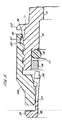
- the end cap 10b is shown partially screwed onto the body to an initial position in which the collet in the cap receives and holds a tube in the coupling body in the "Speedfit" manner. That is to say, the tube is locked in the coupling body but can be released by depressing the collet into the coupling body to release the gripping engagement of the collet with the tube and allow the tube to be withdrawn.
- the end cap 10a has a mouth 31 with a lip around the inner periphery of the mouth.
- the inner side 34 of the end cap has an encircling slot 35 adjacent the mouth, in which the annular diaphragm 30 is snap engageable.
- the mouth of the cap has a bevelled entry indicated at 36 to assist in deforming the diaphragm inwardly as the cap is screwed onto the body and the diaphragm is forced through the mouth of the cap.
- the diameter of the lip at the mouth of the cap at the entry is less than the diameter of the diaphragm but is slightly greater than the rest of the inner diameter of the cap to facilitate entry of the diaphragm into the slot.
- Screwing the cap onto the body causes the diaphragm to snap into the slot 35 at the end nearest the mouth 31 of the cap.
- the cap is then located in the first "Speedfit" position referred to above.
- the bottom wall 37 of the slot is tapered to reduce in diameter towards the open end of the cap so that the diaphragm is held bent over towards the side of the slot adjacent the mouth of the slot.
- the diaphragm is trapped in the corner formed between the bottom wall of the slot and the side wall of the slot when the cap is rotated in a direction to withdraw from the main body to prevent withdrawal of the cap from the main body portion beyond the first position.
- the diaphragm rides up the tapering undercut of the bottom wall of the slot in the cap relaxing the diaphragm slightly, and therefore reducing the resistance to rotation of the cap.
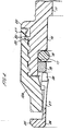
- the cap can then be screwed onto the body until it engages the upstanding end flange 22 of the coupling body as indicated in Figure 4 in which the cap is in the second or "SuperSeal" position.
- the collet is then held in engagement with the end stop in the coupling body and cannot be depressed to allow a tube to be released from the coupling body.
- the arrangement thus provides a tube coupling body which is readily assembled and which provides both "Speedfit” and “SuperSeal” functions without unduly stressing the components of the body.
- This design can also be used on metal coupling bodies or rigid plastic coupling bodies in which case the flexible diaphragm could be moulded on a separate split ring which is assembled into a groove or recess on the body between the thread and the large flange so that the detent engages in the slot on the cap.
- the separate split ring could be mounted in the cap with the flexible diaphragm projecting radially inwardly to engage in a slot in the main body portion.
- the slot in the body portion would be located between the thread and the large flange. Again, the slot in the body could be tapered in diameter.
- the diaphragm could be interrupted once or several times to allow for tooling or to allow the diaphragm's resilient/flexible characteristics to be optimised.
- an enlarged groove 30 is formed at the end of the slot remote from the open end of the cap as illustrated in Figure 5 .
Landscapes
- Engineering & Computer Science (AREA)
- General Engineering & Computer Science (AREA)
- Mechanical Engineering (AREA)
- External Artificial Organs (AREA)
- Quick-Acting Or Multi-Walled Pipe Joints (AREA)
- Infusion, Injection, And Reservoir Apparatuses (AREA)
Claims (12)
- Rohrverbindung (10) mit einem Kupplungskörper (10a) mit einem Durchlass (11), der an einem Ende (12) offen ist, um ein Rohr (13) aufzunehmen, einer Endkappe (10b) im Schraubeingriff mit dem Kupplungskörper (10a) für eine Bewegung zwischen Anfangs-und vorgerückten Positionen entlang des Kupplungskörpers und mit einer Öffnung für das Rohr und mit einer internen Nockenfläche (29), die sich auf die Rohröffnung zuspitzt, einer Klemmhülse (25) in der Endkappe, die mit der Nockenfläche im Eingriff steht, um ein Rohr in der Kappe mit der Bewegung der Klemmhülse (25) aus der Kappe (10b) zu sperren und das Rohr (13) freizugeben, wenn sie in die Kappe (10b) gepresst wird, und mit Stoppmitteln (19) in dem Kupplungskörper (10a), um die Bewegung der Klemmhülse (25) in die Endkappe (10b) zu begrenzen, wobei die Anfangsposition der Endkappe (10b) an dem Kupplungskörper (10a) ermöglicht, dass ein Rohr (13) in die Endkappe (10b) eingesetzt und durch die Klemmhülse (25) versperrt wird und durch Eindrücken der Klemmhülse (25) in die Kappe (10b) freigegeben wird und die vorgerückte Position der Endkappe (10b) die Klemmhülse (25) in der Nähe der Stoppmittel (18, 19) in den Kupplungskörper (10a) hält, um das Freigeben des Rohres (13) zu verhindern,
dadurch gekennzeichnet, dass
der Kupplungskörper einen Außengewindeteil (20) hat, der sich entlang des Kupplungskörpers von dem einen Ende erstreckt, und die Kappe (10b) eine offene Mündung hat, um den Kupplungskörper zu umgeben und einen Gewindeteil hat, der sich von einem Ort in der Nähe der offenen Mündung im Inneren entlang der Endkappe erstreckt, um mit dem Gewindeteil auf dem Kupplungskörper zusammenzuwirken, und dass Sperrmittel zur Verfügung gestellt werden, die zwischen der Kappe (10b) und dem Kupplungskörper (10a) wirken, um zu verhindern, dass die Kappe (10b) von dem Kupplungskörper (10a) von der Anfangsposition losgeschraubt wird, und um es der Kappe (10b) zu erlauben, zwischen der Ausgangsposition und der vorgerückten Position geschraubt zu werden, wobei die Sperrmittel eine flexible Membran (30) umfassen, die den Kupplungskörper neben dem Ende des Gewindes und entfernt von dem offenen Ende des Körpers umgibt, und einen ringförmigen Schlitz (35) innerhalb der Kappe (10b) zwischen dem Gewinde in der Kappe (10b) und der Mündung der Kappe (10b), in den die Membran (30) in der Anfangsposition der Kappe auf dem Kupplungskörper (10a) einschnappt, wobei der Schlitz (35) eine Breite hat, die die Bewegung der Kappe (10b) entlang des Kupplungskörpers (10a) zwischen der Anfangsposition und der vorgerückten Position aufnimmt. - Rohrverbindung nach Anspruch 1, wobei die Sperrmittel (30, 35) einen ansteigenden Widerstand gegen Bewegung der Kappe entlang des Kupplungskörpers von der vorgerückten Position zu der Anfangsposition hin zur Verfügung stellen.
- Rohrverbindung nach Anspruch 1, wobei die Mündung der Kappe mit einer nach innen gewandten Lippe versehen ist, die eine eingeschränkte Öffnung mit kleinerem Durchmesser als dem Außendurchmesser der Membran bildet, und wobei der ringförmige Schlitz die Innenseite der Kappe im Inneren der Lippe umgibt, in welche die ringförmige Membran einschnappen kann, nachdem sie verformt worden ist, wenn sie durch die ringförmige Lippe in der Mündung der Kappe hindurchgegangen ist, um die Anfangsposition der Kappe auf dem Kupplungskörper zu definieren und die Membran in einem verformten Zustand im Eingriff mit dem Boden des Schlitzes zu halten, um einem Herausziehen der Kappe aus dem Kupplungskörper zu widerstehen.
- Rohrverbindung nach Anspruch 3, wobei der ringförmige Schlitz (35) von der Lippe in die Kappe sich nach außen zuspitzt, so dass wenn die Kappe entlang des Kupplungskörpers an der Membran vorbei vorgerückt wird, die Membran entlang des tiefer werdenden Teils des Schlitzes gleiten und sich ausdehnen kann, um die Verformung, mit der die Membran beaufschlagt worden ist, zu verringern.
- Rohrverbindung nach Anspruch 4, wobei der Schlitz (35) in der Kappe (10b) an seinem tieferen Ende einen erweiterten tieferen Schlitz hat, in welchen sich die Membran in der vorgerückten Position der Kappe auf dem Kupplungskörper erstrecken kann, wobei der zusätzliche Schlitz ausreichend tief ist, um die Membran ohne Verformung aufzunehmen.
- Rohrverbindung nach einem der Ansprüche 1 bis 5, wobei die Membran (30) eine einzige, fortlaufende Membran ist, die den Kupplungskörper (10a) umgibt.
- Rohrverbindung nach einem der Ansprüche 1 bis 5, wobei die Membran (30) eine Reihe von Segmenten aufweist, die sich um den Kupplungskörper erstrecken.
- Rohrverbindung nach einem der Ansprüche 1 bis 7, wobei die ringförmige Membran (30) an einem separaten Einsatzring ausgebildet ist, der auf dem Kupplungskörper befestigt ist.
- Rohrverbindung nach Anspruch 8, wobei der Einsetzring ein Schlitzring ist, der in einer Nut in dem Kupplungskörper befestigt ist.
- Rohrverbindung nach einem der Ansprüche 1 bis 9, wobei der Kupplungskörper mit einem äußeren, hochstehenden, ringförmigen Anschlag versehen ist, der sich hinter der Membran des Gewindes auf dem Kupplungskörper befindet, um einen Endanschlag zu schaffen, um das Ausmaß bis zu welchem die Kappe auf den Kupplungskörper aufgeschraubt werden kann, zu beschränken, um die vorgerückte Position zu definieren, in welche die Kappe geschraubt werden kann, um ein Rohr in der Klemmhülse zu sperren.
- Rohrverbindung nach einem der vorstehenden Ansprüche, wobei die Anschlagmittel in dem Kupplungskörper zum Beschränken der Bewegung der Klemmhülse bei Drücken derselben in den Kupplungskörper eine Dichtungsanordnung für ein Rohr aufweisen, die in dem Kupplungskörper liegt.
- Rohrverbindung nach Anspruch 11, wobei die Dichtungsanordnung einen Abstandsring, der den Durchlass in dem Kupplungskörper umgibt, und einen O-Dichtungsring, der zwischen dem Abstandsring und einer Schulter, die in dem Durchlass ausgebildet ist, liegt, aufweist, wobei das innere Ende der Klemmhülse mit dem Abstandsring in Eingriff bringbar ist, um das Eintreten der Klemmhülse in den Kupplungskörper zu beschränken.
Applications Claiming Priority (2)
| Application Number | Priority Date | Filing Date | Title |
|---|---|---|---|
| GBGB0221076.3A GB0221076D0 (en) | 2002-09-11 | 2002-09-11 | Improvements in or relating to tube couplings |
| EP03255651A EP1398559B1 (de) | 2002-09-11 | 2003-09-10 | Verbesserungen betreffend Rohrverbindungen |
Related Parent Applications (2)
| Application Number | Title | Priority Date | Filing Date |
|---|---|---|---|
| EP03255651.6 Division | 2003-09-10 | ||
| EP03255651A Division EP1398559B1 (de) | 2002-09-11 | 2003-09-10 | Verbesserungen betreffend Rohrverbindungen |
Publications (2)
| Publication Number | Publication Date |
|---|---|
| EP1657480A1 EP1657480A1 (de) | 2006-05-17 |
| EP1657480B1 true EP1657480B1 (de) | 2011-03-09 |
Family
ID=9943866
Family Applications (2)
| Application Number | Title | Priority Date | Filing Date |
|---|---|---|---|
| EP06003755A Expired - Lifetime EP1657480B1 (de) | 2002-09-11 | 2003-09-10 | Verbesserungen betreffend Rohrverbindungen |
| EP03255651A Expired - Lifetime EP1398559B1 (de) | 2002-09-11 | 2003-09-10 | Verbesserungen betreffend Rohrverbindungen |
Family Applications After (1)
| Application Number | Title | Priority Date | Filing Date |
|---|---|---|---|
| EP03255651A Expired - Lifetime EP1398559B1 (de) | 2002-09-11 | 2003-09-10 | Verbesserungen betreffend Rohrverbindungen |
Country Status (8)
| Country | Link |
|---|---|
| US (1) | US7032932B2 (de) |
| EP (2) | EP1657480B1 (de) |
| AU (1) | AU2003246038B2 (de) |
| CA (1) | CA2440564C (de) |
| DE (2) | DE60336351D1 (de) |
| ES (2) | ES2256680T3 (de) |
| GB (1) | GB0221076D0 (de) |
| NZ (1) | NZ528153A (de) |
Families Citing this family (60)
| Publication number | Priority date | Publication date | Assignee | Title |
|---|---|---|---|---|
| GB0209897D0 (en) | 2002-04-30 | 2002-06-05 | Guest John Int Ltd | Improvements in or relating to tube couplings |
| JP2005172218A (ja) * | 2003-11-21 | 2005-06-30 | Hama International:Kk | 管継手 |
| TW200602577A (en) | 2004-04-22 | 2006-01-16 | Swagelok Co | Fitting for tube and pipe |
| US7203006B2 (en) * | 2004-08-26 | 2007-04-10 | Sun Long Optics Co., Ltd. | Chucking and focusing device for a telescope eyepiece and its production process |
| GB0504899D0 (en) * | 2005-03-09 | 2005-04-13 | Guest John Int Ltd | Improvements in or relating to tube couplings |
| ITMI20051383A1 (it) * | 2005-07-20 | 2007-01-21 | Faster Spa | Dispositivo di sicurezza per parti assemblate con filettatura relative ad un innesto rapido |
| DE202006006304U1 (de) * | 2006-04-18 | 2007-08-30 | Voss Automotive Gmbh | Steckverbinder für insbesondere aus Kunststoff bestehende Rohrleitungen |
| US7568737B2 (en) * | 2006-09-22 | 2009-08-04 | Eaton Corporation | Male coupling for connecting to female threaded coupling |
| AU2007300473B2 (en) * | 2006-09-22 | 2012-01-19 | Eaton Corporation | Male coupling for connecting to female threaded coupling |
| WO2008057983A1 (en) | 2006-11-02 | 2008-05-15 | Swagelok Company | Pull-up by torque fitting |
| EP2126441A4 (de) * | 2006-11-07 | 2013-01-02 | Yuk Nam Choi | Rohrverbindungsvorrichtungen |
| GB0624784D0 (en) | 2006-12-12 | 2007-01-17 | Guest John Int Ltd | Improvements in or relating to tube couplings |
| WO2008104562A1 (en) * | 2007-03-01 | 2008-09-04 | Georg Fischer Tpa Srl | Joint for connecting pipes |
| AU2008234410B2 (en) * | 2007-03-30 | 2012-06-07 | Sun Chan | Conduit joining apparatus |
| WO2008154076A1 (en) * | 2007-06-12 | 2008-12-18 | Cameron International Corporation | Connector system and method of connecting |
| JP2010535989A (ja) | 2007-08-03 | 2010-11-25 | スウエイジロク・カンパニー | トルクによる引き上げフェルール継手 |
| GB0723646D0 (en) * | 2007-12-03 | 2008-01-16 | Guest John Int Ltd | Tube couplings |
| GB0809685D0 (en) * | 2008-05-28 | 2008-07-02 | Guest John Int Ltd | Improvements in or relating to tube couplings |
| US20100171302A1 (en) * | 2009-01-05 | 2010-07-08 | Nibco Inc. | Push-twist connector |
| US9297481B2 (en) * | 2009-02-20 | 2016-03-29 | Swagelok Company | Conduit fitting with torque collar |
| WO2010096675A1 (en) | 2009-02-20 | 2010-08-26 | Swagelok Company | Conduit fitting with split torque collar |
| WO2011004935A1 (ko) * | 2009-07-08 | 2011-01-13 | (주)스톰테크 | 튜브 커플링 |
| US8157294B2 (en) * | 2009-12-10 | 2012-04-17 | Masco Corporation | Glueless whirlpool fittings |
| US8403370B2 (en) * | 2009-12-17 | 2013-03-26 | Yuk Nam Choi | Pipe coupling device |
| US8833733B2 (en) | 2010-01-21 | 2014-09-16 | Automatic Switch Company | Valve connections |
| US20110204624A1 (en) * | 2010-02-25 | 2011-08-25 | Nibco Inc. | Universal connection socket |
| US8906167B2 (en) | 2010-04-28 | 2014-12-09 | Whirlpool Corporation | Slide assembly for a dishwasher rack |
| GB201010501D0 (en) | 2010-06-22 | 2010-08-04 | Guest John Int Ltd | A tube coupling |
| CN102985740B (zh) | 2010-07-09 | 2016-01-06 | 世伟洛克公司 | 具有挠性扭矩箍的管道接头 |
| CN102330723A (zh) * | 2010-07-13 | 2012-01-25 | 新秩序投资119股份有限公司 | 管配件 |
| GB2482175B (en) * | 2010-07-23 | 2016-01-13 | Agilent Technologies Inc | Fitting element with bio-compatible sealing |
| JP5805981B2 (ja) * | 2011-04-14 | 2015-11-10 | 株式会社ブリヂストン | 継手構造、ヘッダー基体及びヘッダー |
| JP5805980B2 (ja) * | 2011-04-14 | 2015-11-10 | 株式会社ブリヂストン | 管継手及び配管用ヘッダー |
| GB201205575D0 (en) | 2012-03-29 | 2012-05-16 | Guest John Int Ltd | Improvements in or relating to tube couplings |
| KR20140060880A (ko) * | 2012-11-13 | 2014-05-21 | 디케이락 주식회사 | 결합돌기와 첵 마아킹이 형성된 튜브체결구 |
| CN103867820B (zh) * | 2012-12-14 | 2016-12-21 | 林子棋 | 用于管道连接的连接自锁结构 |
| WO2014153608A1 (en) | 2013-03-26 | 2014-10-02 | Gsa Industries (Aust.) Pty. Ltd. | A tube coupling |
| JP5878143B2 (ja) * | 2013-05-08 | 2016-03-08 | 日本ピラー工業株式会社 | 合成樹脂製管継手 |
| KR101452357B1 (ko) * | 2013-07-03 | 2014-10-22 | 디케이락 주식회사 | 관이음 장치 |
| JP6240455B2 (ja) | 2013-10-01 | 2017-11-29 | 日本ピラー工業株式会社 | 合成樹脂製管継手 |
| GB201317952D0 (en) | 2013-10-10 | 2013-11-27 | Guest John Int Ltd | A connector for connecting to a tube |
| GB201317990D0 (en) | 2013-10-11 | 2013-11-27 | Guest John Int Ltd | A conncetor |
| US9447906B2 (en) | 2013-12-11 | 2016-09-20 | Nibco Inc. | Self-locking push-to-connect insert |
| US9541228B2 (en) | 2013-12-11 | 2017-01-10 | Nibco Inc. | Push-to-connect fitting |
| US10006575B2 (en) | 2013-12-11 | 2018-06-26 | Nibco Inc. | Modular push-to-connect assembly |
| AU2014366835B2 (en) | 2013-12-19 | 2019-10-31 | Reliance Worldwide Corporation (Aust.) Pty. Ltd. | Pipe connection fitting |
| US9777875B2 (en) | 2014-02-26 | 2017-10-03 | Nibco Inc. | Clam shell push-to-connect assembly |
| RU2678474C2 (ru) | 2014-05-09 | 2019-01-29 | Своджлок Компани | Фитинг для трубопровода с компонентами, приспособленными для облегчения сборки |
| WO2015187958A1 (en) | 2014-06-04 | 2015-12-10 | Parker-Hannifin Corporation | Compression fitting with torque nut |
| DE102014108699A1 (de) | 2014-06-20 | 2015-12-24 | Alfred Kärcher Gmbh & Co. Kg | Kupplungsanordnung für schraubkupplung |
| CN105402384B (zh) * | 2015-12-16 | 2018-05-29 | 力帆实业(集团)股份有限公司 | 一种油冷管与油冷器的连接结构及一种汽车 |
| WO2017106702A1 (en) * | 2015-12-18 | 2017-06-22 | Nelco Energy Services Llc | Non-preloaded threaded pipe connection for temporary high pressure piping |
| KR102351742B1 (ko) | 2016-03-23 | 2022-01-14 | 스웨이지락 캄파니 | 스트로크 저항 특징부를 갖는 도관 피팅 |
| CN110672177B (zh) * | 2019-10-14 | 2020-11-27 | 山东和同信息科技股份有限公司 | 一种NB-IoT物联网智能水表 |
| JP7344766B2 (ja) * | 2019-11-15 | 2023-09-14 | 日本ピラー工業株式会社 | 管継手 |
| NL2024297B1 (en) * | 2019-11-22 | 2021-08-23 | Wavin Bv | A pipe coupling for receiving, holding and releasing a pipe and a method of assembling a pipe coupling |
| CN112431654B (zh) * | 2020-11-24 | 2022-10-04 | 江苏惠新知识产权服务有限公司 | 一种汽车发动机涡轮增压消音器 |
| KR102323543B1 (ko) * | 2021-02-18 | 2021-11-09 | 에스앤씨코퍼레이션 주식회사 | 파이프 배관용 연결구 |
| US11698153B2 (en) * | 2021-09-24 | 2023-07-11 | Caterpillar Inc. | Fluid joint assembly adjustable from primary to backup sealing state and fluid connector for same |
| US11846375B2 (en) * | 2022-05-16 | 2023-12-19 | Mueller Industries, Inc. | Push-fitting |
Family Cites Families (62)
| Publication number | Priority date | Publication date | Assignee | Title |
|---|---|---|---|---|
| US2475741A (en) * | 1943-01-06 | 1949-07-12 | Robert A Goeller | Connector |
| US2452277A (en) * | 1945-05-10 | 1948-10-26 | George V Woodling | Tube coupling |
| US2640716A (en) * | 1948-12-28 | 1953-06-02 | Arthur L Bigelow | Tube coupling |
| US2728895A (en) * | 1954-10-04 | 1955-12-27 | Whitney Blake Co | Self-locking coupling device |
| NL107650C (de) * | 1956-05-28 | |||
| US3107108A (en) * | 1957-11-26 | 1963-10-15 | Whitney E Greene | Tube coupling |
| US2935299A (en) * | 1957-12-30 | 1960-05-03 | Jansen Gerhart | Clamp nut apparatus |
| US3180664A (en) * | 1961-07-20 | 1965-04-27 | Imp Eastman Corp | Ball pipe joint with composite ball member |
| US3233924A (en) * | 1963-04-18 | 1966-02-08 | Parker Hannifin Corp | High pressure coupling |
| BE656166A (de) * | 1963-11-26 | |||
| US3334661A (en) * | 1964-01-03 | 1967-08-08 | Kenneth A Milette | Pipe union |
| US3250550A (en) * | 1964-02-13 | 1966-05-10 | Gilbert T Lyon | Self-flaring tube coupling |
| FR1508220A (fr) * | 1966-11-21 | 1968-01-05 | Moulages Ind Plasto | Raccord rapide pour tuyaux souples |
| NO126755B (de) * | 1968-05-28 | 1973-03-19 | Raufoss Ammunisjonsfabrikker | |
| CH506743A (de) * | 1969-06-11 | 1971-04-30 | Schmid Kranz & Co Gmbh Zweigni | Rohrverbindungsmuffe für die mechanisch gesicherte Klemmbefestigung glatter Rohrenden - insbesondere kleinkalibriger Stahlrohre |
| US3834742A (en) * | 1971-02-05 | 1974-09-10 | Parker Hannifin Corp | Tube coupling |
| US3747964A (en) * | 1971-12-15 | 1973-07-24 | N Nilsen | Quick coupling and seal |
| FR2227483B1 (de) * | 1973-04-24 | 1975-08-22 | Legris France Sa | |
| GB1520742A (en) * | 1975-07-30 | 1978-08-09 | Guest J D | Couplings for tubes |
| IL47642A (en) * | 1975-07-04 | 1978-07-31 | Plasson Maagan Michael Ind Ltd | Pipe coupling and split-ring useful therein |
| US3989283A (en) * | 1975-07-23 | 1976-11-02 | Genova, Inc. | Compression fitting |
| US4136897A (en) * | 1976-04-08 | 1979-01-30 | Parker-Hannifin Corporation | Coupling device for tubular members |
| US4062572A (en) * | 1976-08-30 | 1977-12-13 | Inner-Tite, A Division Of Yara Engineering Corporation | Transition fittings |
| US4188051A (en) * | 1977-04-22 | 1980-02-12 | Parker-Hannifin Corporation | Tube coupling |
| FR2394736A1 (fr) | 1977-06-16 | 1979-01-12 | Cetri Sa | Raccord de tuyauterie |
| US4305606A (en) * | 1978-11-24 | 1981-12-15 | Societe Legris France S.A. | Quick-releasable connectors for flexible plastic pipes |
| US4253686A (en) * | 1979-04-10 | 1981-03-03 | Aitken W Sidney | Pipe coupling useful at high fluid pressures |
| FR2461186A1 (fr) * | 1979-07-06 | 1981-01-30 | Legris | Perfectionnement aux raccords pour tuyauteries notamment pour tuyauteries de fluides a haute pression |
| US4335908A (en) * | 1980-05-19 | 1982-06-22 | Burge Donald G | Push-in tube connector |
| US4298222A (en) * | 1980-07-23 | 1981-11-03 | Jaco Manufacturing Company | Tube coupling |
| SE455638B (sv) * | 1982-08-27 | 1988-07-25 | Ekman K R | Anordning vid en kopplingsenhet med forsta och andra mutterformade kopplingsdelar samt sett for framstellning av anordningen |
| ES274252Y (es) * | 1983-08-05 | 1984-08-16 | Cuerda Zamora Pedro | Dispositivo de acoplamiento con garras basculantes de retencion |
| IN164968B (de) | 1984-11-12 | 1989-07-15 | Guest John D | |
| US4655159A (en) * | 1985-09-27 | 1987-04-07 | Raychem Corp. | Compression pressure indicator |
| CH672898A5 (de) * | 1987-05-11 | 1990-01-15 | Praezisions Werkzeuge Ag | |
| US4867489A (en) * | 1987-09-21 | 1989-09-19 | Parker Hannifin Corporation | Tube fitting |
| JPH0633844B2 (ja) * | 1987-09-29 | 1994-05-02 | ブリヂストンフロ−テック株式会社 | 管継手 |
| CA1311778C (en) * | 1988-05-12 | 1992-12-22 | Anthony L. Reese | Compression coupling |
| US4993755A (en) * | 1989-09-22 | 1991-02-19 | Master Industries, Inc. | Quick connect fitting |
| US5388866A (en) * | 1990-03-09 | 1995-02-14 | Lourdes Industries | High pressure coupling with provision for preventing separation of parts and with anti-galling provision |
| US5217261A (en) * | 1990-04-23 | 1993-06-08 | Aeroquip Corporation | Flareless compression fitting |
| JPH0439492A (ja) * | 1990-05-31 | 1992-02-10 | Tokai Rubber Ind Ltd | クイックコネクタ |
| US5362110A (en) * | 1991-02-25 | 1994-11-08 | Moeller Manufacturing Co., Inc. | Fluid coupling and fastener capture device |
| FR2689205B1 (fr) * | 1992-03-30 | 1995-08-11 | Hutchinson | Dispositif adaptateur pour raccorder un embout et l'extremite d'un flexible, en particulier d'un flexible gaz. |
| AU668316B2 (en) * | 1993-07-20 | 1996-04-26 | Philmac Pty Ltd | Coupling for outer surface engagement of polymeric pipe |
| FR2710715B1 (fr) * | 1993-09-29 | 1996-09-20 | Marc Jean Pierre | Verrou auto-bloquant pour canalisations. |
| FR2717883B1 (fr) * | 1994-03-04 | 1996-06-14 | Hutchinson | Dispositif de raccordement rapide et étanche pour conduites tubulaires. |
| TW309581B (de) * | 1994-09-15 | 1997-07-01 | Environ Prod Inc | |
| US5466019A (en) * | 1994-09-26 | 1995-11-14 | Komolrochanaporn; Naris | Pipe coupling |
| JP3644786B2 (ja) * | 1997-04-14 | 2005-05-11 | Smc株式会社 | 管継手 |
| IT1293211B1 (it) * | 1997-05-14 | 1999-02-16 | Irritec S R L | Dispositivo di accoppiamento filettato per tubazioni. |
| US6095572A (en) * | 1998-01-20 | 2000-08-01 | Optimize Technologies, Inc. | Quarter turn quick connect fitting |
| GB9806642D0 (en) | 1998-03-27 | 1998-05-27 | Guest John D | Improvements in or relating to tube coupling |
| US5957509A (en) * | 1998-10-16 | 1999-09-28 | Komolrochanaporn; Naris | Pipe coupling |
| US6302447B1 (en) * | 1999-06-11 | 2001-10-16 | Airdrome Parts Co. | Self-locking coupling device |
| DE60011359T2 (de) | 1999-09-27 | 2005-06-16 | Legris S.A. | Vorrichtung zum Verbinden von einem Leitungsende mit einem Anschlussteil |
| GB0103774D0 (en) * | 2001-02-15 | 2001-04-04 | Guest John Int Ltd | Improvements in or relating to tube couplings |
| US6796586B2 (en) * | 2001-07-09 | 2004-09-28 | Twin Bay Medical, Inc. | Barb clamp |
| GB0126798D0 (en) * | 2001-11-07 | 2002-01-02 | Guest John Int Ltd | Improvements in or relating to tube couplings |
| GB0209899D0 (en) | 2002-04-30 | 2002-06-05 | Guest John Int Ltd | Improvements in or relating to tube couplings |
| GB0209897D0 (en) | 2002-04-30 | 2002-06-05 | Guest John Int Ltd | Improvements in or relating to tube couplings |
| US6905142B2 (en) * | 2002-09-25 | 2005-06-14 | Huck Patents, Inc. | Hydraulic coupling |
-
2002
- 2002-09-11 GB GBGB0221076.3A patent/GB0221076D0/en not_active Ceased
-
2003
- 2003-09-10 ES ES03255651T patent/ES2256680T3/es not_active Expired - Lifetime
- 2003-09-10 DE DE60336351T patent/DE60336351D1/de not_active Expired - Lifetime
- 2003-09-10 EP EP06003755A patent/EP1657480B1/de not_active Expired - Lifetime
- 2003-09-10 DE DE60303890T patent/DE60303890T2/de not_active Expired - Lifetime
- 2003-09-10 ES ES06003755T patent/ES2362793T3/es not_active Expired - Lifetime
- 2003-09-10 CA CA2440564A patent/CA2440564C/en not_active Expired - Lifetime
- 2003-09-10 EP EP03255651A patent/EP1398559B1/de not_active Expired - Lifetime
- 2003-09-11 AU AU2003246038A patent/AU2003246038B2/en not_active Expired
- 2003-09-11 NZ NZ528153A patent/NZ528153A/en not_active IP Right Cessation
- 2003-09-11 US US10/660,099 patent/US7032932B2/en not_active Expired - Lifetime
Also Published As
| Publication number | Publication date |
|---|---|
| ES2256680T3 (es) | 2006-07-16 |
| NZ528153A (en) | 2004-07-30 |
| DE60336351D1 (de) | 2011-04-21 |
| EP1398559A1 (de) | 2004-03-17 |
| EP1398559B1 (de) | 2006-03-08 |
| HK1084719A1 (en) | 2006-08-04 |
| EP1657480A1 (de) | 2006-05-17 |
| DE60303890D1 (de) | 2006-05-04 |
| CA2440564A1 (en) | 2004-03-11 |
| DE60303890T2 (de) | 2006-11-16 |
| AU2003246038B2 (en) | 2008-08-21 |
| US20040061329A1 (en) | 2004-04-01 |
| ES2362793T3 (es) | 2011-07-13 |
| GB0221076D0 (en) | 2002-10-23 |
| AU2003246038A1 (en) | 2004-04-01 |
| US7032932B2 (en) | 2006-04-25 |
| CA2440564C (en) | 2010-04-13 |
Similar Documents
| Publication | Publication Date | Title |
|---|---|---|
| EP1657480B1 (de) | Verbesserungen betreffend Rohrverbindungen | |
| EP1701080B1 (de) | Verbesserungen betreffend Rohrkupplungen | |
| EP1359363B1 (de) | Rohrverbindung | |
| US6880865B2 (en) | Tube couplings | |
| US6056326A (en) | Tube couplings | |
| EP2644958B1 (de) | Rohrkupplung | |
| US5370423A (en) | Tube couplings | |
| US7100948B2 (en) | Tube couplings | |
| EP0564132B1 (de) | Kupplungen | |
| EP0554111B1 (de) | Verbesserungen in bezug auf Gewindeteile | |
| JP4701068B2 (ja) | 管継手 | |
| HK1084719B (en) | Improvements in and relating to tube couplings | |
| US6874758B2 (en) | Handle assembly for faucet | |
| JP2006009997A (ja) | 管継手 | |
| JP3035736B2 (ja) | 可撓管継手 |
Legal Events
| Date | Code | Title | Description |
|---|---|---|---|
| PUAI | Public reference made under article 153(3) epc to a published international application that has entered the european phase |
Free format text: ORIGINAL CODE: 0009012 |
|
| 17P | Request for examination filed |
Effective date: 20060223 |
|
| AC | Divisional application: reference to earlier application |
Ref document number: 1398559 Country of ref document: EP Kind code of ref document: P |
|
| AK | Designated contracting states |
Kind code of ref document: A1 Designated state(s): DE ES FR GB IT |
|
| REG | Reference to a national code |
Ref country code: HK Ref legal event code: DE Ref document number: 1084719 Country of ref document: HK |
|
| 17Q | First examination report despatched |
Effective date: 20060711 |
|
| AKX | Designation fees paid |
Designated state(s): DE ES FR GB IT |
|
| GRAP | Despatch of communication of intention to grant a patent |
Free format text: ORIGINAL CODE: EPIDOSNIGR1 |
|
| GRAS | Grant fee paid |
Free format text: ORIGINAL CODE: EPIDOSNIGR3 |
|
| GRAA | (expected) grant |
Free format text: ORIGINAL CODE: 0009210 |
|
| AC | Divisional application: reference to earlier application |
Ref document number: 1398559 Country of ref document: EP Kind code of ref document: P |
|
| AK | Designated contracting states |
Kind code of ref document: B1 Designated state(s): DE ES FR GB IT |
|
| REG | Reference to a national code |
Ref country code: GB Ref legal event code: FG4D |
|
| REF | Corresponds to: |
Ref document number: 60336351 Country of ref document: DE Date of ref document: 20110421 Kind code of ref document: P |
|
| REG | Reference to a national code |
Ref country code: DE Ref legal event code: R096 Ref document number: 60336351 Country of ref document: DE Effective date: 20110421 |
|
| REG | Reference to a national code |
Ref country code: ES Ref legal event code: FG2A Ref document number: 2362793 Country of ref document: ES Kind code of ref document: T3 Effective date: 20110713 |
|
| REG | Reference to a national code |
Ref country code: HK Ref legal event code: GR Ref document number: 1084719 Country of ref document: HK |
|
| PLBE | No opposition filed within time limit |
Free format text: ORIGINAL CODE: 0009261 |
|
| STAA | Information on the status of an ep patent application or granted ep patent |
Free format text: STATUS: NO OPPOSITION FILED WITHIN TIME LIMIT |
|
| 26N | No opposition filed |
Effective date: 20111212 |
|
| REG | Reference to a national code |
Ref country code: DE Ref legal event code: R097 Ref document number: 60336351 Country of ref document: DE Effective date: 20111212 |
|
| REG | Reference to a national code |
Ref country code: FR Ref legal event code: PLFP Year of fee payment: 14 |
|
| REG | Reference to a national code |
Ref country code: FR Ref legal event code: PLFP Year of fee payment: 15 |
|
| REG | Reference to a national code |
Ref country code: FR Ref legal event code: PLFP Year of fee payment: 16 |
|
| PGFP | Annual fee paid to national office [announced via postgrant information from national office to epo] |
Ref country code: GB Payment date: 20220927 Year of fee payment: 20 Ref country code: DE Payment date: 20220928 Year of fee payment: 20 |
|
| PGFP | Annual fee paid to national office [announced via postgrant information from national office to epo] |
Ref country code: FR Payment date: 20220926 Year of fee payment: 20 |
|
| PGFP | Annual fee paid to national office [announced via postgrant information from national office to epo] |
Ref country code: IT Payment date: 20220926 Year of fee payment: 20 Ref country code: ES Payment date: 20221003 Year of fee payment: 20 |
|
| REG | Reference to a national code |
Ref country code: DE Ref legal event code: R071 Ref document number: 60336351 Country of ref document: DE |
|
| REG | Reference to a national code |
Ref country code: ES Ref legal event code: FD2A Effective date: 20230927 |
|
| REG | Reference to a national code |
Ref country code: GB Ref legal event code: PE20 Expiry date: 20230909 |
|
| PG25 | Lapsed in a contracting state [announced via postgrant information from national office to epo] |
Ref country code: GB Free format text: LAPSE BECAUSE OF EXPIRATION OF PROTECTION Effective date: 20230909 Ref country code: ES Free format text: LAPSE BECAUSE OF EXPIRATION OF PROTECTION Effective date: 20230911 |