EP1657519A1 - Une poignée d'arme à feu, particulièrement de pistolet - Google Patents
Une poignée d'arme à feu, particulièrement de pistolet Download PDFInfo
- Publication number
- EP1657519A1 EP1657519A1 EP05425708A EP05425708A EP1657519A1 EP 1657519 A1 EP1657519 A1 EP 1657519A1 EP 05425708 A EP05425708 A EP 05425708A EP 05425708 A EP05425708 A EP 05425708A EP 1657519 A1 EP1657519 A1 EP 1657519A1
- Authority
- EP
- European Patent Office
- Prior art keywords
- gripping portion
- grip according
- development direction
- strike
- grip
- Prior art date
- Legal status (The legal status is an assumption and is not a legal conclusion. Google has not performed a legal analysis and makes no representation as to the accuracy of the status listed.)
- Withdrawn
Links
- 230000008878 coupling Effects 0.000 claims description 19
- 238000010168 coupling process Methods 0.000 claims description 19
- 238000005859 coupling reaction Methods 0.000 claims description 19
- 230000003247 decreasing effect Effects 0.000 claims description 3
- 238000005452 bending Methods 0.000 description 2
- 230000006978 adaptation Effects 0.000 description 1
- 238000007792 addition Methods 0.000 description 1
- 230000001419 dependent effect Effects 0.000 description 1
- 210000005224 forefinger Anatomy 0.000 description 1
- 238000003780 insertion Methods 0.000 description 1
- 230000037431 insertion Effects 0.000 description 1
- 230000002452 interceptive effect Effects 0.000 description 1
- 238000004519 manufacturing process Methods 0.000 description 1
- 238000000034 method Methods 0.000 description 1
- 238000012986 modification Methods 0.000 description 1
- 230000004048 modification Effects 0.000 description 1
- 230000007704 transition Effects 0.000 description 1
Images



Classifications
-
- F—MECHANICAL ENGINEERING; LIGHTING; HEATING; WEAPONS; BLASTING
- F41—WEAPONS
- F41C—SMALLARMS, e.g. PISTOLS, RIFLES; ACCESSORIES THEREFOR
- F41C23/00—Butts; Butt plates; Stocks
- F41C23/10—Stocks or grips for pistols, e.g. revolvers
Definitions
- the object of the present invention is a firearm grip, particularly of a gun.
- Gun grips which comprise a rear gripping portion, commonly called the “backstrap”, which is removably fixed onto a grip body such that, when necessary, it may be replaced with others of a different finishing, material, shape and size in order to best suit the hand of the shooter for whom the gun is intended.
- backstrap a rear gripping portion
- Prior art guns provide a number of embodiments of coupling or locking means between the backstrap and the grip body.
- a first example of known coupling means is a peg being arranged transversal to the backstrap and in a rear area of the grip between respective seats of the backstrap and the body.
- the backstrap has been provided as an integral part of an extension of the cartridge-housing magazine which is adapted to be inserted in the bottom of the grip body.
- the known solutions suffer from some drawbacks.
- the known solutions cannot ensure the optimum coupling of the backstrap to the body, while avoiding steps or incorrect alignment of the parts.
- a good level of coupling and continuity has been achieved between the body and the backstrap, though the provided coupling means have proved rather complicated both when being manufactured and when used by the shooter.
- the problem at the heart of the present invention is to provide a firearm grip, particularly of a gun, which has such structural and functional characteristics as to overcome said drawbacks stated with reference to the
- the problem at the heart of the present invention is to provide a grip in which the backstrap can be firmly and effectively coupled with the body without any step being present between the body and the backstrap, such that the shooter has- a feeling of continuity of the grip.
- a further problem at the heart of the present invention is to provide a variant embodiment of the known grips which is easier both to manufacture and to be used by the shooter.
- a grip of a firearm 12, particularly of a gun has been overall designated with 10.
- a grip body substantially extending in a development direction 16 has been designated with 14.
- the development direction 16 of body 14 is arranged substantially transversal to a barrel of the gun, not shown.
- the body 14 of the grip 10 is provided as one piece with the portion adapted to house the gun barrel, thereby providing the so-called frame of the weapon.
- a grip portion removably mounted on the body 14 in a rear area relative to a trigger of the weapon has been designated with 20.
- the term “rear” will designate herein below a portion or a surface opposite the trigger or muzzle. Consequently, the term “front” will designate a portion or a surface arranged on the side of the trigger or muzzle, whereas the term “side” will indicate a joining portion or surface between the front portion and the rear portion. Furthermore, the terms “upper” and “lower” have been used with reference to the normal use of a weapon hold by a shooter and considering a vertical direction.
- the gripping portion 20 partially covers the body 14.
- the gripping portion 20 is adapted to be a rest for a portion of the user's palm and forefinger, opposite the muzzle and trigger.
- the gripping portion 20 is also called the "backstrap".
- the gripping portion 20 is adapted to envelop and cover, at least partially, a rear surface 14a and a tract of side surfaces 14b of the body 14, relative to a plane transversal to the development direction 16 of the body.
- the transversal section of the gripping portion 20 is substantially U-shaped, the curved connecting tract being adapted to cover the rear surface of the body 14, whereas both arms of the "U" are adapted to cover respective tracts of side surfaces of the body 14.
- the body 14 has a notch 22 adapted to receive the gripping portion 20.
- the gripping portion 20 continues the surface of the body portions being adjacent to the gripping portion and the grip has a substantially continuous outer surface and without steps in the transition area between the body and the gripping portion.
- the gripping portion 20 is advantageously adapted to be inserted on the body 14 in an inserting direction 24 transversal to the development direction 16 of body 14.
- the gripping portion 20 comprises an outer surface 26 adapted to be hold by the user and an inner surface 28 facing the body 14.
- the outer surface 26 can be either decorated or have relieves thereon or however be adapted to be properly and comfortably hold by the user.
- Fig. 11 there is shown a half of the gripping portion 20, according to a possible embodiment, as seen from the inside thereof.
- a first relief 30 advantageously develops in the direction transversal to the development direction 16 of the body 14 following the curvature of the gripping portion 20. In other words, a relief 30 extends in the gripping portion enveloping direction on the body.
- a first relief 30 substantially extends along the rear portion and along the side portions of the gripping portion 20, optionally with different thicknesses, preferably decreasing from the side portion towards the rear portion (Fig. 11).
- the first relieves can mostly extend only at the side portions of the gripping portion.
- the gripping portion 20 comprises a plurality of first relieves 30 repeating in the development direction 16 of the body 14 alternating with matching first recesses 32.
- the edge of the inner surface 28 of the gripping portion 20 preferably has a substantially toothed shape.
- a groove running in the development direction 16 of the body 14 has been designated with 34.
- the groove 34 runs through the first relieves 30.
- the groove 34 is preferably arranged in a side portion of the gripping portion. Still more preferably, each of the two side portions of the gripping portion has a respective groove 34.
- the side edges of the gripping portion 20 comprise a overhanging portion 36 having a lower thickness than the gripping portion and arranged towards the inner surface 28.
- the overhanging portion 36 involves the whole height of the gripping portion 20 in the development direction 16 of body 14.
- the overhanging portion 36 has a first inclined surface 38 arranged transversally between the inner surface 28 and the outer surface 26 of the gripping portion.
- the first inclined surface 38 is arranged such that the inner surface 28 continues beyond the outer surface 26.
- the body 14 comprises second relieves 40.
- the second relieves 40 extend at the rear portion and at tracts of the side portions of the body 14.
- the second relieves 40 extend from the side surfaces 14b and the rear surface 14a of the body 14 facing the inner surface 28 of the gripping portion 20.
- a second relief 40 develops in the direction transversal to the development direction 16 of body 14 following the curvature of the body. In other words, a second relief 40 extends in the gripping portion enveloping direction on the body 14.
- the second relieves 40 extend in the direction transversal to the development direction 16 of the body 14 with different thicknesses, preferably decreasing from the side portion to the rear portion (Fig. 7).
- the second relieves 40 mostly extend at the side portions of the body.
- the body 14 comprises a plurality of second relieves 40 repeating along the development direction 16 of the body 14 alternating with corresponding second recesses 42.
- the edge of the rear or side portion of the body preferably has a substantially toothed shape.
- the- second relieves 40 repeat along the development direction 16 of the body 14 alternating with and offset relative to the first relieves 30, such that a first relief 30 of the gripping portion 20 is adapted to be inserted in a corresponding second recess 42 of the body 14 and a second relief 40 of the body 14 is adapted to be inserted in a first recess 32 of the gripping portion 20.
- the second relieves 40 of the body have a lower extension than the first relieves 30 of the gripping portion, with reference to the direction transversal to the development direction of the body.
- the second relieves 40 of the body 14 advantageously end at this groove.
- the body comprises a seat 44 extending in the development direction 16 of the body, at side edges of the notch 22.
- each of the side portions of the body 14 comprises a respective seat 44.
- the seat 44 involves the whole height of the gripping portion 20 in the development direction 16 of the body 14.
- the seat 44 comprises a second inclined surface 46 arranged transversally between the side surface 14b and the outer surface of the body 14.
- the second inclined surface 46 is parallel and suitable to abut against the corresponding first inclined surface 38 of the gripping portion.
- the grip 10 comprises interference means 48 comprising an interference element adapted to be inserted between the gripping portion 20 and the body 14 to lock the gripping portion on the body in the inserting direction 24, i.e. in a direction transversal to the development direction 16.
- the interference element comprises at least one substantially rectilinear bar 50.
- the interference element is advantageously adapted to be inserted in a space 51 defined by the side surface 14b of the body 14 and the inner surface 28 of the gripping portion 20.
- the interference element is suitable to be inserted along the groove 34 of the gripping portion.
- the interference element is adapted to be inserted in both side portions of the gripping portion and the body.
- the interference element is U-shaped, each rectilinear tract (the bar 50) is inserted in a side portion of the gripping portion and the body.
- the rectilinear tracts of the U-shaped interference element are at an angle in the vicinity of the respective connecting portion 50a.
- each bar 50 has a slight bending P such that the lower part of the U is slightly bent forward relative to the remaining rectilinear tract of the bars 50.
- the grip according to the present invention advantageously comprises means for locking the gripping portion 20 on the body 14 in the inserting direction of the gripping portion 24 on the body.
- the locking means comprise first strikes 52 that are associated with the gripping portion 20 and offset in the development direction 16 of the body 14 relative to second strikes 54 being associated with the body.
- the locking means further comprise the interference means 48 interposed between the first and second strikes for locking the gripping portion in the inserting direction 24.
- the first relieves 30 define said first strikes 52 of the gripping portion, whereas the second relieves 40 define said second strikes 54 of the body.
- the first and second relieves define mutual first and second abutment surfaces 56, 58 adapted to interact with the interference means (Fig. 7).
- the first and second abutment surfaces extend in the development direction 16 of the body 14.
- an end portion of the first relieves 30 defines a first strike 52 and a first abutment surface 56 with the interference means.
- an end portion of the second relieves 40 defines a second strike 54 and a second abutment surface 58 with the interference means.
- the first strike 52 and the first abutment surface 56 are defined by the groove 34.
- first and second abutment surfaces 56, 58 are respective head surfaces of the respective relieves.
- the locking means are arranged along at least one side portion of the body and the gripping portion, preferably along both side portions of the body and the gripping portion.
- the locking means comprise a plurality of first strikes 52 in the gripping portion which are arranged in the development direction 16 of the body and a plurality of second strikes 54 of the body which are arranged in the development direction 16 of the body.
- the first strikes alternate with second strikes and are offset relative thereto in the development direction 16 of the body 14.
- first and second strikes 52, 54 are formed in respective mutually facing surfaces of the gripping portion and the body.
- the interference element develops along the development direction of the body and is inserted between the first strikes 52 and the second strikes 54 in the development direction 16 of the body 14.
- the grip according to the invention comprises guide means between the gripping portion 20 and the body 14 for the gripping portion to be inserted on the body according to the inserting direction 24 transversal to the development direction 16 of the body.
- the guide means further define means for locking the gripping portion on the body in the development direction 16 of the body 14.
- the guide means define the first strikes 52 and the second strikes 54 of the means for locking the gripping portion 20 on the body 14 operating in the inserting direction of the gripping portion 20 on the body.
- the guide means define a shape coupling between the facing surfaces of the gripping portion 20 and the body 14. Furthermore, the shape coupling is suitable to lock the gripping portion 20 on the body 14 in the development direction 16 of the body.
- the shape coupling between the facing surfaces of the gripping portion 20 and the body 14 extends transversally to the development direction 16, substantially in the gripping portion enveloping direction on the body.
- the shape coupling between the facing surfaces of the gripping portion and the body is repeated in the development direction 16 of the body.
- first relieves 30 and second relieves 40 define said shape coupling and said guide means as well as the means for locking the gripping portion on the body in the development direction of the body.
- the grip according to the present invention comprises means for fastening the side edges of the gripping portion 20 on the body 14.
- the fastening_means comprise a shape coupling between the side edges of the gripping portion and the body.
- the overhanging portion 36 and the respective seat 44 define said shape coupling.
- the side edges of the gripping portion are provided to comprise the first inclined surface 38 suitable to abut against the corresponding second inclined surface 46 of the body 14.
- the outer surface of the gripping portion 20 is flush with the outer surface of the body portion 20 adjacent to the gripping portion.
- a peg for fixing a plug 62 of the weapon frame has been designated with 60.
- the peg 60 is adapted to be housed in a through seat 64 of the body 14 arranged transversal to the development direction 16 between the two side surfaces 14b of the body 14.
- the gripping portion 20 mounted on the body 14 covers the peg 60 and the through seat 64.
- the interference element 48 is adapted to be arranged on the through seat 64 and the peg 60 in order to prevent the latter from coming off.
- the peg is arranged at the bending P of the interference element.
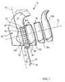
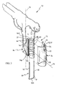
- the present invention further relates to a kit comprising a grip 10 provided with a gripping portion 20 and further gripping portions 20a, 20b that differ from each other by shape and/or size and/or material and/or surface finishing (Fig. 1 and 2).
- Each further gripping portion 20a, 20b comprises the elements described above with reference to the gripping portion 20.
- Fig. 7-10 show a few assembly steps.
- the selected gripping portion is approached to the body 14 in the inserting direction 24, i.e. transversal to the development direction 16 of the body 14 (Fig. 7).
- the first relieves 30 of the gripping portion 20 slide between the second relieves 40, within the second recesses 42 of the body 14, thereby guiding the gripping portion 20 in position, such that the first strikes 52 alternate with and are offset relative to the second strikes 54.
- the gripping portion 20 is inserted on the body 14 until the grooves 34 exceed the ends of the second relieves 40.
- the respective first and second abutment surfaces 56, 58 are arranged- in- a direction parallel to the development direction 16 of the body 14, alternating and offset in this direction, respectively. Furthermore, the respective first and second abutment surfaces 56, 58 mutually face inwards towards the respective groove 34 at a distance depending on the working tolerances and which should theoretically correspond to the width of the groove 34.
- the overhanging portions 36 of the gripping portion insert in the respective seats 44 of the body until the respective first and second inclined surfaces 38, 46 abut against each other.
- the gripping portion 20 envelops and encompasses the body 14 within the notch 22, such that the shooter does not feel any steps or irregularity between the body outer surface and the gripping portion.
- the interference means 48 and particularly the interference element is inserted along the groove 34, i.e. between the first abutment surfaces 56 and the second abutment surfaces 58.
- both bars 50 fit into the respective grooves 34 whereas the connecting portion 50a of the "U" abuts against the lower part of the body.
- the grip body 14 comprises at least one step 66 adapted to receive the connecting portion 50a, particularly when the interference element 48 has a lower portion inclined forward.
- Fig. 8 shows a cross section of the assembled grip.
- the interference means will fit between the first abutment surfaces 56 and the second abutment surfaces 58 thereby moving them apart from each other and forcing the overhanging portions 36 inside the respective seats 44, such as illustrated for example in Fig. 9 and 10.
- the interference means prevent the gripping portion from coming off the body according to a direction transversal to the development direction of the body (i.e. according to the inserting direction).
- Fig. 4 shows the grip when assembled, the gripping portion 20 being marked with a dotted line and in phantom.
- the first relieves 30 (first strikes 52) are marked with a dotted line to show their position relative to the second relieves 40 (second strikes 54).
- the interference element 48 is inserted between the first and second strikes that- are arranged alternating in the development direction 16. As a consequence, the fastening between the gripping portion and the body is distributed through the entire height of the gripping portion according to the development direction 16. Furthermore, both side portions of the gripping portion are fastened to the body.
- the interference element is removed from the respective grooves 34 in the development direction of the body.
- the interference element can be grasped from the connecting portion 50a for the same to be removed below the grip.
- first and second strikes are free to mutually slide in the inserting direction 24 and the gripping portion can be removed from the body in the inserting direction, obviously in the opposite way to the actual insertion way.
- both the assembly and disassembly steps obtained by inserting or removing the interference element can be simplified.
- the locking function can be provided either on a plurality of abutment surfaces or abutment surfaces that also involve the entire height of the gripping portion.
- the interference elements can be introduced between the gripping portion and the body -without then interfering with the shooter's grip.
- guide means By providing at least one relief on the body and gripping portion that are mutually offset in the development direction of the body, guide means can be obtained which facilitate the introduction of the gripping portion on the body.
- the guide means can advantageously define means for locking the gripping portion on the body in the development direction of the body.
- a further advantage of the grip according to the invention is that, due to the uncommon structural simplicity of the same, it can be manufactured at a very low cost and used by the shooter in an immediate and intuitive manner.
- the relieves can have a different shape or size- from -what has been illustrated in the figures.
- the relieves can be provided only in the side portions of the gripping portion and the body.
- the first relieves can only consist of the end portions outside the groove 34.
- the interference means can be different from those illustrated.
- a right interference element and a left interference element or only one interference element with a shape other than that illustrated may be provided.
- the fastening means of the side edges can have a configuration other than that illustrated.
- the overhanging portions and the respective seats can provide a step shape or other shapes allowing the edges of the gripping portion to be inserted within body seats.
- the interference means can be introduced at the fastening means, by providing a through hole extending in the overhanging portion in the development direction of the body and respective through holes in the body for receiving the interference element.
Landscapes
- Engineering & Computer Science (AREA)
- General Engineering & Computer Science (AREA)
- Toys (AREA)
- Lock And Its Accessories (AREA)
- Motorcycle And Bicycle Frame (AREA)
- Purses, Travelling Bags, Baskets, Or Suitcases (AREA)
- Casings For Electric Apparatus (AREA)
- Aiming, Guidance, Guns With A Light Source, Armor, Camouflage, And Targets (AREA)
Applications Claiming Priority (1)
| Application Number | Priority Date | Filing Date | Title |
|---|---|---|---|
| IT002166A ITMI20042166A1 (it) | 2004-11-11 | 2004-11-11 | Impugnatura di arma da fuoco in particolare pistola |
Publications (1)
| Publication Number | Publication Date |
|---|---|
| EP1657519A1 true EP1657519A1 (fr) | 2006-05-17 |
Family
ID=35520847
Family Applications (1)
| Application Number | Title | Priority Date | Filing Date |
|---|---|---|---|
| EP05425708A Withdrawn EP1657519A1 (fr) | 2004-11-11 | 2005-10-10 | Une poignée d'arme à feu, particulièrement de pistolet |
Country Status (9)
| Country | Link |
|---|---|
| US (1) | US7748153B2 (fr) |
| EP (1) | EP1657519A1 (fr) |
| CN (1) | CN1773209A (fr) |
| AR (1) | AR051624A1 (fr) |
| BR (1) | BRPI0504516A (fr) |
| IT (1) | ITMI20042166A1 (fr) |
| MX (1) | MXPA05012172A (fr) |
| RU (1) | RU2005134945A (fr) |
| ZA (1) | ZA200508436B (fr) |
Cited By (7)
| Publication number | Priority date | Publication date | Assignee | Title |
|---|---|---|---|---|
| WO2009097873A1 (fr) * | 2008-02-04 | 2009-08-13 | Heckler & Koch Gmbh | Poignée auxiliaire pour une arme à feu portative |
| EP1876409A3 (fr) * | 2006-07-05 | 2010-03-17 | Cressi-Sub S.p.A. | Fusil lance-harpon pour plongeur sous-marin avec poignée réglable |
| EP2336708A1 (fr) | 2009-12-16 | 2011-06-22 | Fabbrica d'Armi Pietro Beretta S.p.A. | Pistolet avec fixation pour cordon de sécurité |
| EP2179244A4 (fr) * | 2007-07-25 | 2012-06-27 | Sturm Ruger & Co | Dos de crosse réversible pour arme à feu |
| EP3063493A4 (fr) * | 2013-11-01 | 2017-06-28 | Sturm, Ruger & Company, Inc. | Arme à feu à poignée remplaçable |
| DE102019105244A1 (de) * | 2019-03-01 | 2020-09-03 | Gema Switzerland Gmbh | Heckschale für eine sprühpistole sowie sprühpistole mit einer solchen heckschale |
| USD996557S1 (en) * | 2021-07-20 | 2023-08-22 | John Lyles | Universal heated hand grip |
Families Citing this family (38)
| Publication number | Priority date | Publication date | Assignee | Title |
|---|---|---|---|---|
| US7694449B1 (en) | 2004-02-25 | 2010-04-13 | Pontillo Ii James V | Plastic pistols |
| DE102005016020A1 (de) * | 2005-04-07 | 2006-10-12 | Heckler & Koch Gmbh | Schußwaffengriff und Bausatz mit Wechselteilen hierfür |
| US20070256347A1 (en) * | 2006-05-02 | 2007-11-08 | Fitzpatrick Richard M | Modular handgrip |
| US20100139144A1 (en) * | 2006-05-02 | 2010-06-10 | Magpul Industries, Corp. | Modular Handgrip |
| US20100281741A1 (en) * | 2007-01-09 | 2010-11-11 | Gibson Michael H | Removable hand protector for semi automatic pistols |
| AT508316B1 (de) * | 2009-04-16 | 2011-05-15 | Glock Gaston Ing | Griffstück für eine feuerwaffe |
| US8146580B2 (en) * | 2009-12-03 | 2012-04-03 | Ho-Sheng Wei | Structure for opening grip cover of toy gun |
| US8490311B2 (en) * | 2010-01-11 | 2013-07-23 | Hogue, Inc. | Firearm grip sleeve with retention feature |
| US8151504B1 (en) * | 2010-01-14 | 2012-04-10 | Stark Equipment Corp. | Ergonomic firearm grip |
| US8950098B2 (en) * | 2010-02-19 | 2015-02-10 | Steven C. Sims | Shock, muzzle jump, and felt recoil reducers for handguns |
| US8181378B2 (en) * | 2010-06-01 | 2012-05-22 | Derik Losinger | Wraparound gun grip |
| US20130205635A1 (en) * | 2010-09-08 | 2013-08-15 | Steve Hines | Grip insert for glock handgun |
| USD658262S1 (en) * | 2010-10-01 | 2012-04-24 | Prezine, Llc | Upper grip panel |
| US9982963B2 (en) | 2012-02-21 | 2018-05-29 | Lanny L. Johnson | Firearm having tactile biofeedback reference feature |
| US10371481B2 (en) | 2012-02-21 | 2019-08-06 | Lanny L. Johnson | Tactile biofeedback reference attachment |
| US8671605B2 (en) * | 2012-08-17 | 2014-03-18 | Bruce K. Siddle | Off-trigger locator |
| USD755326S1 (en) | 2014-09-02 | 2016-05-03 | Bruce K. Siddle | Firearm with off-trigger locator |
| USD755327S1 (en) | 2014-09-02 | 2016-05-03 | Bruce K. Siddle | Off-trigger locator attachment |
| USD767075S1 (en) | 2015-02-19 | 2016-09-20 | David A. Grossman | Ergonomic grip for a slide of semiautomatic firearm |
| US10054392B2 (en) | 2015-04-25 | 2018-08-21 | Samuel P. Maroney | Grip sleeve for firearm |
| US9851174B1 (en) * | 2015-05-21 | 2017-12-26 | Derek J. BAILEY | Pistol with improved grip |
| US9777984B1 (en) | 2015-07-20 | 2017-10-03 | David Kristopher Bonine | Skeletonized grip for an automatic rifle having interchangeable grip panels |
| USD813339S1 (en) * | 2016-04-25 | 2018-03-20 | Samuel P. Maroney | Firearm grip sleeve |
| CN105890453A (zh) * | 2016-06-14 | 2016-08-24 | 浙江新华机械制造有限公司 | 一种提高手枪寿命的机械结构 |
| CN106767151B (zh) * | 2016-12-16 | 2018-06-29 | 重庆建设工业(集团)有限责任公司 | 一种组合式枪械握把 |
| USD840492S1 (en) | 2017-02-10 | 2019-02-12 | AIM Sports Inc. | Featureless backstrap for a grip for firearms |
| USD840491S1 (en) | 2017-02-10 | 2019-02-12 | AIM Sports Inc. | Featureless backstrap for a grip for firearms |
| USD846681S1 (en) * | 2017-05-26 | 2019-04-23 | Smith & Wesson Corp. | Pistol with grip safety |
| USD883413S1 (en) * | 2017-08-16 | 2020-05-05 | Wilson's Gun Shop, Inc | Handgun slide |
| US10731936B1 (en) * | 2019-03-19 | 2020-08-04 | Kimber Ip, Llc | Modular grip panel system for a firearm |
| US11079189B2 (en) | 2019-12-05 | 2021-08-03 | Blackhawk Manufacturing Group Inc. | Modular handgun grip assembly |
| US11274901B2 (en) * | 2020-05-29 | 2022-03-15 | Joshua K. Burgess | Modular weapon foregrip |
| EP4202348B1 (fr) * | 2021-12-23 | 2024-01-31 | Glock Technology GmbH | Module de poignée pour une arme de poing |
| US20250314451A1 (en) * | 2022-10-03 | 2025-10-09 | Axts Inc | Attachment interface for recoil environments |
| US12259212B1 (en) * | 2023-02-07 | 2025-03-25 | Strike IP, LLC | Firearm grip insert with secondary lock |
| WO2024184339A1 (fr) * | 2023-03-06 | 2024-09-12 | ARSENAL COLLECTION s.r.o. | Crosse-pistolet modulaire |
| TR2023002951A2 (tr) * | 2023-03-16 | 2023-05-22 | Cakir Said Yusuf | Bi̇r kabza aparati |
| US12339094B2 (en) * | 2023-10-23 | 2025-06-24 | Axts Inc. | Attaching a grip attachment or other attachment in a recoil environment at threadless region(s) |
Citations (4)
| Publication number | Priority date | Publication date | Assignee | Title |
|---|---|---|---|---|
| US4286401A (en) * | 1979-04-23 | 1981-09-01 | Pachmayr Gun Works, Inc. | Cushioned gun grip |
| US4936036A (en) * | 1989-06-26 | 1990-06-26 | Smith & Wesson Corp. | Integral grip construction for handguns |
| US6112446A (en) * | 1997-03-20 | 2000-09-05 | Sig Arms International Ag | Replaceable weapon grip |
| US6802148B1 (en) * | 2003-04-01 | 2004-10-12 | Gregory A. Danas | Target grip apparatus for a firearm |
Family Cites Families (14)
| Publication number | Priority date | Publication date | Assignee | Title |
|---|---|---|---|---|
| US4043066A (en) * | 1976-06-07 | 1977-08-23 | Pachmayr Gun Works, Inc. | Pistol grip |
| US4199887A (en) * | 1977-09-23 | 1980-04-29 | Guy Hogue | One piece hand grip for pistol |
| US4397109A (en) * | 1981-02-04 | 1983-08-09 | Pachmayr Gun Works, Inc. | Structure and mounting of gun cartridge clip pads |
| US4602450A (en) * | 1983-07-13 | 1986-07-29 | Pachmayr Gun Works, Inc. | Forend structure for pistol conversion assembly |
| US4586282A (en) * | 1983-10-03 | 1986-05-06 | Bangor Punta Corporation | Grip assembly for a handgun |
| US4833812A (en) * | 1988-05-16 | 1989-05-30 | Farrar Frank W | Yieldably reinforced gun grip |
| USD305923S (en) * | 1989-02-13 | 1990-02-06 | Smith & Wesson Corp. | Grip for handgun |
| US5231237A (en) * | 1992-01-08 | 1993-07-27 | Pachmayr Ltd. | Gun grip assembly |
| USD374903S (en) * | 1994-04-22 | 1996-10-22 | Pearce Grip, Inc. | Pistol grip |
| US5768817A (en) * | 1997-01-28 | 1998-06-23 | Simons; Terence J. | Gun handle grip |
| US6301818B1 (en) * | 2000-03-06 | 2001-10-16 | Patrick L. Hogue | Synthetic grip for a handgun handle and method of installation |
| US6964382B2 (en) * | 2002-08-30 | 2005-11-15 | Illinois Tool Works Inc. | Grip cover for coating dispensing device hand grip |
| ITMI20042449A1 (it) * | 2004-12-22 | 2005-03-22 | Beretta Armi Spa | Pistola con guancia intercambiabile |
| ATE419504T1 (de) * | 2006-06-23 | 2009-01-15 | Sat Swiss Arms Technology Ag | Griffstück für eine handfeuerwaffe |
-
2004
- 2004-11-11 IT IT002166A patent/ITMI20042166A1/it unknown
-
2005
- 2005-10-10 EP EP05425708A patent/EP1657519A1/fr not_active Withdrawn
- 2005-10-18 ZA ZA200508436A patent/ZA200508436B/xx unknown
- 2005-10-20 BR BRPI0504516-9A patent/BRPI0504516A/pt not_active IP Right Cessation
- 2005-10-28 US US11/260,379 patent/US7748153B2/en not_active Expired - Fee Related
- 2005-11-09 AR ARP050104691A patent/AR051624A1/es unknown
- 2005-11-10 RU RU2005134945/02A patent/RU2005134945A/ru not_active Application Discontinuation
- 2005-11-10 CN CN200510115756.1A patent/CN1773209A/zh active Pending
- 2005-11-11 MX MXPA05012172A patent/MXPA05012172A/es unknown
Patent Citations (4)
| Publication number | Priority date | Publication date | Assignee | Title |
|---|---|---|---|---|
| US4286401A (en) * | 1979-04-23 | 1981-09-01 | Pachmayr Gun Works, Inc. | Cushioned gun grip |
| US4936036A (en) * | 1989-06-26 | 1990-06-26 | Smith & Wesson Corp. | Integral grip construction for handguns |
| US6112446A (en) * | 1997-03-20 | 2000-09-05 | Sig Arms International Ag | Replaceable weapon grip |
| US6802148B1 (en) * | 2003-04-01 | 2004-10-12 | Gregory A. Danas | Target grip apparatus for a firearm |
Cited By (8)
| Publication number | Priority date | Publication date | Assignee | Title |
|---|---|---|---|---|
| EP1876409A3 (fr) * | 2006-07-05 | 2010-03-17 | Cressi-Sub S.p.A. | Fusil lance-harpon pour plongeur sous-marin avec poignée réglable |
| EP2179244A4 (fr) * | 2007-07-25 | 2012-06-27 | Sturm Ruger & Co | Dos de crosse réversible pour arme à feu |
| WO2009097873A1 (fr) * | 2008-02-04 | 2009-08-13 | Heckler & Koch Gmbh | Poignée auxiliaire pour une arme à feu portative |
| EP2336708A1 (fr) | 2009-12-16 | 2011-06-22 | Fabbrica d'Armi Pietro Beretta S.p.A. | Pistolet avec fixation pour cordon de sécurité |
| US8438772B2 (en) | 2009-12-16 | 2013-05-14 | Fabbrica d 'Armi Pietro Beretta S.p.A. | Gun with fastening for safety cord |
| EP3063493A4 (fr) * | 2013-11-01 | 2017-06-28 | Sturm, Ruger & Company, Inc. | Arme à feu à poignée remplaçable |
| DE102019105244A1 (de) * | 2019-03-01 | 2020-09-03 | Gema Switzerland Gmbh | Heckschale für eine sprühpistole sowie sprühpistole mit einer solchen heckschale |
| USD996557S1 (en) * | 2021-07-20 | 2023-08-22 | John Lyles | Universal heated hand grip |
Also Published As
| Publication number | Publication date |
|---|---|
| ZA200508436B (en) | 2006-08-30 |
| BRPI0504516A (pt) | 2006-06-27 |
| US7748153B2 (en) | 2010-07-06 |
| ITMI20042166A1 (it) | 2005-02-11 |
| RU2005134945A (ru) | 2007-05-20 |
| CN1773209A (zh) | 2006-05-17 |
| AR051624A1 (es) | 2007-01-24 |
| MXPA05012172A (es) | 2006-05-15 |
| US20060096147A1 (en) | 2006-05-11 |
Similar Documents
| Publication | Publication Date | Title |
|---|---|---|
| US7748153B2 (en) | Firearm grip, particularly of a gun | |
| US6112446A (en) | Replaceable weapon grip | |
| US5584136A (en) | Magazine adapter | |
| EP0272819B1 (fr) | Poignée d'arme de poing | |
| US7886473B2 (en) | Stocks and casing for a rifle | |
| US4495720A (en) | Handgun magazine with pommel base | |
| US7937874B2 (en) | Firearm grips and firearm grip construction sets | |
| CN104380029B (zh) | 弹药匣 | |
| US6401379B1 (en) | Handgun having a polymer frame | |
| US4286401A (en) | Cushioned gun grip | |
| US20180328681A1 (en) | Pistol Multi-Functional Rear Rail Module | |
| US6802148B1 (en) | Target grip apparatus for a firearm | |
| DE102013008091B4 (de) | Pistole mit einem Verschlussschlitten sowie Verschlussschlitten für eine Pistole mit einer daran jeweils angeordneten Durchladehilfe und Durchladehilfe für den Verschlussschlitten | |
| US20150101230A1 (en) | Lower receiver for firearms | |
| CA2351173C (fr) | Systeme de boite de culasse pour arme automatique ou pistolet mitrailleur | |
| WO2014110335A1 (fr) | Système de crosse interchangeable pour armes à feu | |
| US20120167431A1 (en) | Magazine well grip | |
| US7698844B2 (en) | Box magazine for a firearm | |
| US12281868B2 (en) | Increased capacity ammunition magazine | |
| US12320606B2 (en) | Modular pistol grip | |
| US9857147B2 (en) | Rail system for a rifle | |
| US10054381B1 (en) | Slide assembly quick release pin with arm extension | |
| US4290220A (en) | Lightweight stock and frame construction for a firearm | |
| US6301818B1 (en) | Synthetic grip for a handgun handle and method of installation | |
| US4063379A (en) | Fore end assembly for a firearm |
Legal Events
| Date | Code | Title | Description |
|---|---|---|---|
| PUAI | Public reference made under article 153(3) epc to a published international application that has entered the european phase |
Free format text: ORIGINAL CODE: 0009012 |
|
| AK | Designated contracting states |
Kind code of ref document: A1 Designated state(s): AT BE BG CH CY CZ DE DK EE ES FI FR GB GR HU IE IS IT LI LT LU LV MC NL PL PT RO SE SI SK TR |
|
| AX | Request for extension of the european patent |
Extension state: AL BA HR MK YU |
|
| 17P | Request for examination filed |
Effective date: 20061004 |
|
| 17Q | First examination report despatched |
Effective date: 20061103 |
|
| AKX | Designation fees paid |
Designated state(s): AT BE BG CH CY CZ DE DK EE ES FI FR GB GR HU IE IS IT LI LT LU LV MC NL PL PT RO SE SI SK TR |
|
| AXX | Extension fees paid |
Extension state: HR Payment date: 20061004 |
|
| GRAP | Despatch of communication of intention to grant a patent |
Free format text: ORIGINAL CODE: EPIDOSNIGR1 |
|
| STAA | Information on the status of an ep patent application or granted ep patent |
Free format text: STATUS: THE APPLICATION IS DEEMED TO BE WITHDRAWN |
|
| 18D | Application deemed to be withdrawn |
Effective date: 20100302 |