EP1657529B1 - Indicateur numérique - Google Patents
Indicateur numérique Download PDFInfo
- Publication number
- EP1657529B1 EP1657529B1 EP04425849A EP04425849A EP1657529B1 EP 1657529 B1 EP1657529 B1 EP 1657529B1 EP 04425849 A EP04425849 A EP 04425849A EP 04425849 A EP04425849 A EP 04425849A EP 1657529 B1 EP1657529 B1 EP 1657529B1
- Authority
- EP
- European Patent Office
- Prior art keywords
- display
- indicator
- indicator instrument
- instrument
- control circuit
- Prior art date
- Legal status (The legal status is an assumption and is not a legal conclusion. Google has not performed a legal analysis and makes no representation as to the accuracy of the status listed.)
- Expired - Lifetime
Links
- 238000004891 communication Methods 0.000 claims description 22
- 230000006870 function Effects 0.000 claims description 11
- 238000005259 measurement Methods 0.000 claims description 10
- 230000001360 synchronised effect Effects 0.000 claims description 9
- 230000004913 activation Effects 0.000 claims description 6
- 238000000034 method Methods 0.000 claims description 3
- 230000003213 activating effect Effects 0.000 claims description 2
- 239000000446 fuel Substances 0.000 description 6
- 239000003921 oil Substances 0.000 description 5
- 230000000007 visual effect Effects 0.000 description 5
- 238000013461 design Methods 0.000 description 4
- 238000004458 analytical method Methods 0.000 description 3
- 238000004519 manufacturing process Methods 0.000 description 3
- 230000002547 anomalous effect Effects 0.000 description 2
- 238000010586 diagram Methods 0.000 description 2
- 239000011159 matrix material Substances 0.000 description 2
- XLYOFNOQVPJJNP-UHFFFAOYSA-N water Substances O XLYOFNOQVPJJNP-UHFFFAOYSA-N 0.000 description 2
- 238000004590 computer program Methods 0.000 description 1
- 238000010276 construction Methods 0.000 description 1
- 238000009434 installation Methods 0.000 description 1
- 230000001795 light effect Effects 0.000 description 1
- 238000007726 management method Methods 0.000 description 1
- 239000000463 material Substances 0.000 description 1
- 238000012544 monitoring process Methods 0.000 description 1
- 239000010705 motor oil Substances 0.000 description 1
- 230000005855 radiation Effects 0.000 description 1
- 230000011664 signaling Effects 0.000 description 1
Images


Classifications
-
- G—PHYSICS
- G01—MEASURING; TESTING
- G01D—MEASURING NOT SPECIALLY ADAPTED FOR A SPECIFIC VARIABLE; ARRANGEMENTS FOR MEASURING TWO OR MORE VARIABLES NOT COVERED IN A SINGLE OTHER SUBCLASS; TARIFF METERING APPARATUS; MEASURING OR TESTING NOT OTHERWISE PROVIDED FOR
- G01D7/00—Indicating measured values
Definitions
- Present invention generally relates to indicator instruments apt to display, used in combination with measuring devices or sensors, values representative of executed measurements.
- present invention relates to indicator instruments (indicators or instruments) of digital type that are used, for example, in nautical, auto-motive, aeronautical and aerospace field.
- Indicators apt to be used in the nautical, auto-motive, aeronautical and aerospace areas are known in the art. Such indicators allow the user to analyse at any given moment the state of the value of interest, which may be, for example, the battery voltage, the fuel level, the engine oil pressure, the water temperature, etc.
- an indicator instrument for motor vehicles including a pointer arranged for selectively indicating different ranges of values and a switch arranged for manually selecting the range of values to be indicated.
- a common problem with all the above known indicators is that they can solely perform a certain function which is "wired" to the indicator itself during manufacturing.
- Such a thing, "wiring a function" during manufacturing implies that an indicator buyer may solely use the indicator for performing the function it has been bought for, that is, for example, the function of fuel indicator, if that was the expected function, or the function of indicator of other certain values on the basis of respective buy expectations.
- the stated problem does strongly limit the flexibility both of the manufacturer and of the buyer of such instruments or indicators and that, therefore, it would be desirable to make available indicators that have flexible characteristics that would allow to overcome the mentioned problem.
- a measuring instrument including first display elements for displaying numerical values and further display elements for displaying a digital representation of the measured values.
- a multifunctional measurement device or multitester 5 in 1 including a display for displaying measurement values and a range selector or switch arranged for manually selecting the range of values to be measured and displayed.
- the known multimeter includes a display and a switch for manually selecting the range of values to be measured and displayed.
- a common problem of the above instruments or devices is that they are arranged for displaying a selected range of values by manually selecting the range of values to be measured and displayed.
- Object of present invention is a digital type indicator apt to overcome the above mentioned limits.
- the invention also relates to a measuring system comprising the indicator instrument according to the invention, a matrix of indicator instruments, a method for configuring the indicator instrument as well as a computer program product loadable in the memory of at least one computer and including software code portions for configuring the indicator instrument according to the invention.
- Claims are an integral part of the teaching pertaining to the present invention.
- the indicator instrument of present invention is configured for being externally programmed, whereby for certain function to be carried out they may be selectively chosen as a function of a certain measuring device connected or connectable to the indicator instrument.
- the indicator instrument of present invention is configurable even after, for example, its installation in the vehicle or boat dashboard.
- the indicator instrument may be combined with other instruments or indicators of the same type or of a different type and may be used synchronically with other indicators for indicating, for example, alarm conditions.
- a measuring and displaying system used, for example, in the nautical, auto-motive, aeronautical, aerospace fields, comprises an indicator instrument (indicator or digital indicator) 12, according to present invention, and a measuring or measurement device 15, of known type, connected in a known way, to the indicator instrument 12 and capable of transmitting to the same indicator 12 values indicative of the measurements to be displayed, for example, by the same indicator 12.
- the indicator 12 comprises a display device (display) 20 and a control circuit 30.
- the control circuit 30 is connected both to the measuring device 15 (sensor) and, as will be explained later in more detail, to the display 20 for transmitting to this display 20 values measured by a certain measuring device 15.
- the display 20 ( Fig.1 and Fig.2 ) comprises a plurality of display entities (entities), 22, 25, 26, 28, 29 respectively, that are selectively actuatable and that are arranged for displaying, for example, graphical symbols and/or measured values and/or measurement units and leaving invisible entities that are not selected.
- the display 20, comprises a plurality of icons 22, for example 4 icons, representing each a different sensor 15 connectable to the indicator 12; a plurality of indicators of units of measure 29, for example 9 indicators that are selectable during the pre-setting phase at the factory that manufactures the indicator 12; and a plurality of external arrow-shaped marks 25 that are apt to provide graphical indications proportional, in a predetermined range, to the value measured by the measuring device 15.
- the display 20 further comprises an alphanumeric display 26, for example an alphanumeric display having three digits comprised each of 7 segments and a dot.
- an alphanumeric display 26 is configured, for example, for displaying numerical indications of values measured by the measuring device 15.
- the display 20 also comprises a further alphanumeric display 28, for example an alphanumeric display having four digits comprised each of 7 segments.
- This further alphanumeric display 28 is configured, for example, for displaying a predetermined measurement range.
- the display 20 as described is apt to display , for example, when it is connected to a temperature sensor:
- the indicator 12 When the indicator 12 is connected to a pressure sensor, for example an oil pressure sensor, it is apt to display:
- the indicator 12 when the indicator 12 is connected to a battery, it can display the indication of the voltmeter or of the amperometer through an icon representing a battery. In such a case the unit of measure indicated on the display will be, respectively, Volt or Ampere.
- the consumption indication icon displayed corresponds to the fuel indicator.
- the icon will be lighted steadily or it will be flashing.
- the unit of measure for the fuel consumption will be, for example 1/h (litres/hour).
- the four digit alphanumeric display 28 may be used for indicating the measurement range relating the entity measured by the sensor 15 connected to the indicator 12.
- the range indication may be selected on the basis of the programs (firmware or software) developed during the indicator 12 design phase, whether in factory, for example if it is a fixed type range (i.e. a range having constant extremes), or may be updated in field, for example if it is a variable type range that changes depending on the type of the measured value.
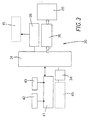
- the control circuit 30 ( Fig.1 , Fig.3 ) comprises a microprocessor circuit (microcontroller) 31, a first interface circuit 36, placed between the microcontroller 31 and the sensor 15, and a second interface circuit 41, placed between the microcontroller 31 and light effect devices 42, for example LEDs (Light Emitting Diodes), and/or acoustic alarms 43.
- microprocessor circuit microcontroller
- first interface circuit 36 placed between the microcontroller 31 and the sensor 15
- a second interface circuit 41 placed between the microcontroller 31 and light effect devices 42, for example LEDs (Light Emitting Diodes), and/or acoustic alarms 43.
- the second interface circuit 41 may be further connected to the external marks 25 (not depicted in Fig.3 ) and configured for activating, under the microcontroller 31 control, a visual alarm through the flashing of the marks, if the entities measured by the sensor 15 connected to the indicator 12 are out of a predetermined range.
- the control circuit 30 also comprises, a controller 35, for example a serial type controller, placed between the microcontroller 31 and the display 20 and capable of handling communications between the microcontroller 31 and the display 20.
- a controller 35 for example a serial type controller
- control circuit 30 connected to the microcontroller 31 comprises a communication device 34, for example a communication port that is apt to handle alternatively the serial protocol RS232 or the I2C (Inter Integrated Circuits) protocol, of known type.
- a communication device 34 for example a communication port that is apt to handle alternatively the serial protocol RS232 or the I2C (Inter Integrated Circuits) protocol, of known type.
- the communication device 34 is configured for enabling communications between the microcontroller 31 and external devices 45.
- the communication device 34 on the basis of programs or program modules (firmware or software) developed in the indicator 12 design phase and stored on the microcontroller 31 when configured as a serial port, is apt to allow communications to and from external programming devices (for example a Personal Computer).
- external programming devices for example a Personal Computer
- the communication device 34 on the basis of programs (firmware or software) developed in the indicator 12 design phase and stored on the microcontroller 31, when configured in accordance with the I2C protocol, is apt to enable the indicator instrument 12 to communicate, for example, with other instruments or indicators configured with the same type of protocol.
- one of the indicator instruments 12 is set up, in factory for example, as a master indicator or as an indicator having high priority.
- the master indicator when it is necessary, as for example in case of displaying synchronous alarms (i.e. when it could be of use to display multiple and synchronous visual alarm signals), the master indicator is apt to activate the synchronous alarms on the connected indicators by means of suitable commands.
- the operation of the indicator instrument 12 as disclosed may be, for example, the following one.
- the indicator instrument 12 As soon as the indicator is assembled but, for example, not installed in an instrument panel, the indicator instrument 12, thanks to the programs stored on the microcontroller 31, is configured either in the factory or in the field, by means of a PC and through the communication device 34, in order to be connected, for example, to any sensor of a predetermined list.
- the serial communication port actuatable through the communication device 34 it is possible, by means of an external Personal Computer (PC), to set up the indicator either during the production or during delivery and/or retail sales.
- PC Personal Computer
- Such a set up is possible, for example, through a Visual Basic interface that may be stored, for example, on the PC memory and configured, according to a preferred embodiment, in order to allow to select, for example, a group of parameters of the indicator instrument from a set of parameters listed hereafter:
- the communication device 34 and the software interface is apt to allow, for example, to modify on site the indicator or instrument set up, i.e. even after the instrument has been installed in the instrument panel.
- the indicator instrument 12 is installed, for example in a single instrument panel, together with one or a plurality of instruments of the same type and such instruments are interconnected through the communication device 34, then in the presence, for example, of an alarm signal reported by an instrument with high priority this instrument will send a signal through the network I2C to other instruments in order to activate alarms synchronously.
- Applicant believes that such an example of danger situations management could be one among other possible innovative characteristics of present invention: according to the above example it is possible to conduct the contemporary analysis of all the measured values and it is possible to identify anomalous situations not reportable through a single value analysis.
- the alarm conditions are set up, for example, during a programming phase and are managed by a master or high priority indicator (selected during the set up phase through the communication device 34).
- a master or high priority indicator selected during the set up phase through the communication device 34.
- the master indicator will activate synchronous alarms.
- the indicator instrument is an innovative digital indicator fully configurable and capable of providing the user with the value information of an entity both in numeric form and in graphic form.
- the instrument is apt to replace, without any other interface device, the pointer type indicators, that are still in use, for example in the nautical, auto-motive, aeronautical, aerospace fields now.
- the instrument according to present invention is apt to provide the user with a set of important advantages either mechanical and electrical, or ergonomic and aesthetic.
- One of the objectives of the instrument is to perform, for example, a function of an instrument with double indication of values.
- This instrument should be configurable and should be able to comprise in one sole instrument the characteristics of a plurality of measuring instruments. At the same time it should be completely compatible with other pointer indicators available in the market.
- the display and the implemented control logic make the instrument very simple in use, with high reading precision, neither requiring calibration nor having mechanical friction due to the lack of moving mechanical parts.
- the use of electronic circuitry permits, for example, to have an instrument of lesser thickness. This is achieved by reducing the overall dimensions and will allow to install it either in a predetermined socket on the dashboard or directly on the dashboard.
Landscapes
- Physics & Mathematics (AREA)
- General Physics & Mathematics (AREA)
- Arrangements For Transmission Of Measured Signals (AREA)
- Indicating Measured Values (AREA)
- Liquid Crystal (AREA)
- Infusion, Injection, And Reservoir Apparatuses (AREA)
- Electrotherapy Devices (AREA)
- Holo Graphy (AREA)
- Electric Clocks (AREA)
- Optical Filters (AREA)
- Optical Communication System (AREA)
Claims (9)
- Instrument indicateur comprenant :- un dispositif d'affichage (20) ;- un circuit de commande (30) connecté au dit dispositif d'affichage (20) et agencé pour transmettre au dit dispositif d'affichage (20) des signaux indiquant des valeurs mesurées par un certain type de dispositif de mesure (15) pouvant être connecté au dit circuit de commande (30) ; ledit dispositif d'affichage (20) comportant une pluralité d'entités d'affichage (22, 25, 26, 28, 29) qui peuvent être actionnées de façon sélective par ledit circuit de commande (30) en vue de rendre visibles les entités d'affichage sélectionnées et pour laisser invisibles les entités d'affichage non sélectionnées de ladite pluralité d'entités d'affichage (22, 25, 26, 28, 29) ;caractérisé en ce que
ledit circuit de commande (30) comprend :- un dispositif de communications (34) apte à être connecté à un dispositif externe (45) configuré pour régler ledit circuit de commande (30) afin d'actionner sélectivement ladite pluralité d'entités d'affichage (22, 25, 26, 28, 29) sur la base du type de dispositif de mesure (15) pouvant être connecté au dit circuit de commande (30). - Instrument indicateur (12) selon la revendication 1, caractérisé en ce que ladite pluralité d'entités d'affichage (22, 25, 26, 28, 29) comporte des entités d'affichage pouvant être sélectionnées à partir d'un groupe comprenant- des icônes (22) représentant des types d'instrument de mesure ;- des marques graphiques (25) ;- des entités d'affichage (26, 28) permettant d'afficher des valeurs numériques.
- Instrument indicateur (12) selon la revendication 1 ou 2, caractérisé en ce que ledit dispositif de communications (34) est configuré sous la forme d'un port de type série.
- Instrument indicateur (12) selon la revendication 1 ou 2, caractérisé en ce que ledit dispositif de communications (34) est apte à être connecté à au moins un instrument indicateur supplémentaire (12) en vue de communiquer avec ledit au moins un instrument indicateur supplémentaire (12) à travers un certain protocole de communications.
- Instrument indicateur (12) selon la revendication 4 caractérisé en ce que ledit certain protocole de communications est un protocole de Circuits Inter Intégrés (12C).
- Instrument indicateur (12) selon la revendication 4 ou 5 configuré pour coopérer avec ledit au moins un instrument indicateur supplémentaire (12) afin d'activer des alarmes synchrones comportant des fonctions sélectionnées à partir du groupe constituées par :- une activation synchrone de dispositifs d'affichage (20) associés auxdits instruments indicateurs (12) interconnectés les uns avec les autres ;- une activation en alternance desdits dispositifs d'affichage (20) ;- une activation combinée de ladite activation asynchrone et de ladite activation en alternance.
- Système de mesure comprenant au moins un premier instrument indicateur (12) selon les revendications 1 à 6 et au moins un premier dispositif de mesure (15) connecté au dit instrument indicateur (12).
- Système de mesure selon la revendication 7 comportant- au moins un second instrument indicateur (12) et au moins un second dispositif de mesure (15) connecté au dit second instrument indicateur (12) ;
ledit premier instrument indicateur ayant un premier niveau de priorité, et ledit second instrument indicateur étant connecté au dit premier instrument indicateur et ayant un second niveau de priorité inférieur au dit premier niveau de priorité ;
de sorte que ledit premier instrument indicateur (12) est configuré en vue d'activer des fonctions prédéterminées et coordonnées dudit premier instrument indicateur (12) et dudit second instrument indicateur (12) sur la base des mesures effectuées par ledit premier type de dispositif de mesure (15) et/ou par ledit second type de dispositif de mesure (15). - Procédé servant à configurer un dispositif indicateur (12) comportant un dispositif d'affichage (20) et un circuit de commande (30) connecté au dit dispositif d'affichage (20) ;
dans lequel ledit dispositif d'affichage (20) comprend une pluralité d'entités d'affichage (22, 25, 26, 28, 29) qui peuvent être actionnées sélectivement par ledit circuit de commande (30) en vue de rendre visibles des entités d'affichage sélectionnées et de laisser invisibles des entités d'affichage non sélectionnées de ladite pluralité d'entités d'affichage (22, 25, 26, 28, 29) ;
caractérisé par l'étape consistant à- régler au moyen d'un dispositif externe (45) ledit circuit de commande (30) pour activer de façon sélective ladite pluralité d'entités d'affichage (22, 25, 26, 28, 29) sur la base du type de dispositif de mesure (15) pouvant être connecté au dit circuit de commande (30).
Priority Applications (11)
| Application Number | Priority Date | Filing Date | Title |
|---|---|---|---|
| ES04425849T ES2345549T3 (es) | 2004-11-15 | 2004-11-15 | Indicador digital. |
| EP04425849A EP1657529B1 (fr) | 2004-11-15 | 2004-11-15 | Indicateur numérique |
| DE602004026074T DE602004026074D1 (de) | 2004-11-15 | 2004-11-15 | Digitale Anzeige |
| SI200431442T SI1657529T1 (sl) | 2004-11-15 | 2004-11-15 | Digitalni prikazovalnik |
| AT04425849T ATE461427T1 (de) | 2004-11-15 | 2004-11-15 | Digitale anzeige |
| RU2007122342/28A RU2007122342A (ru) | 2004-11-15 | 2005-07-18 | Цифровой индикатор |
| NZ555858A NZ555858A (en) | 2004-11-15 | 2005-07-18 | Digital indicator |
| PCT/IB2005/002167 WO2006051358A1 (fr) | 2004-11-15 | 2005-07-18 | Afficheur numerique |
| US11/667,760 US20080169935A1 (en) | 2004-11-15 | 2005-07-18 | Digital Indicator |
| AU2005303551A AU2005303551A1 (en) | 2004-11-15 | 2005-07-18 | Digital indicator |
| NO20072453A NO20072453L (no) | 2004-11-15 | 2007-05-11 | Digital indikator |
Applications Claiming Priority (1)
| Application Number | Priority Date | Filing Date | Title |
|---|---|---|---|
| EP04425849A EP1657529B1 (fr) | 2004-11-15 | 2004-11-15 | Indicateur numérique |
Publications (2)
| Publication Number | Publication Date |
|---|---|
| EP1657529A1 EP1657529A1 (fr) | 2006-05-17 |
| EP1657529B1 true EP1657529B1 (fr) | 2010-03-17 |
Family
ID=34932886
Family Applications (1)
| Application Number | Title | Priority Date | Filing Date |
|---|---|---|---|
| EP04425849A Expired - Lifetime EP1657529B1 (fr) | 2004-11-15 | 2004-11-15 | Indicateur numérique |
Country Status (11)
| Country | Link |
|---|---|
| US (1) | US20080169935A1 (fr) |
| EP (1) | EP1657529B1 (fr) |
| AT (1) | ATE461427T1 (fr) |
| AU (1) | AU2005303551A1 (fr) |
| DE (1) | DE602004026074D1 (fr) |
| ES (1) | ES2345549T3 (fr) |
| NO (1) | NO20072453L (fr) |
| NZ (1) | NZ555858A (fr) |
| RU (1) | RU2007122342A (fr) |
| SI (1) | SI1657529T1 (fr) |
| WO (1) | WO2006051358A1 (fr) |
Families Citing this family (2)
| Publication number | Priority date | Publication date | Assignee | Title |
|---|---|---|---|---|
| CA2616192A1 (fr) * | 2007-10-31 | 2009-04-30 | Textron Inc. | Etat combine d'indicateur de charge et de jauge a essence |
| JP2016114365A (ja) * | 2014-12-11 | 2016-06-23 | 日本精機株式会社 | 車両用計器 |
Family Cites Families (9)
| Publication number | Priority date | Publication date | Assignee | Title |
|---|---|---|---|---|
| US4787040A (en) * | 1986-12-22 | 1988-11-22 | International Business Machines Corporation | Display system for automotive vehicle |
| DE8912505U1 (de) * | 1989-10-21 | 1989-12-07 | Shang-Wen, Chang, Shin Tien, Taipei | Meßinstrument |
| US5301553A (en) * | 1989-12-20 | 1994-04-12 | Tjs Development Corporation | Apparatus for remote sensing and receiving |
| BR9206542A (pt) * | 1991-09-25 | 1995-05-02 | Houston Digital Instr Inc | Dispositivo mostrador e de medição de variável de processo |
| JP4187329B2 (ja) * | 1997-11-21 | 2008-11-26 | オメガ エンジニアリング,インコーポレイテッド | 片手持ち型の計器を用いた放射率の表示方法及び放射率の表示手段を備える片手持ち型の計器 |
| DE19939631A1 (de) * | 1999-08-20 | 2001-02-22 | Nokia Mobile Phones Ltd | Multimediaeinheit |
| US6696932B2 (en) * | 2000-09-08 | 2004-02-24 | Eaton Corporation | Intelligent indicators for a motor vehicle |
| US6870469B2 (en) * | 2001-01-26 | 2005-03-22 | Komatsu Ltd. | Display controller for display device of vehicle |
| DE10310233A1 (de) * | 2003-03-08 | 2004-09-16 | Adam Opel Ag | Zeigerinstrument für ein Kraftfahrzeug |
-
2004
- 2004-11-15 DE DE602004026074T patent/DE602004026074D1/de not_active Expired - Lifetime
- 2004-11-15 EP EP04425849A patent/EP1657529B1/fr not_active Expired - Lifetime
- 2004-11-15 ES ES04425849T patent/ES2345549T3/es not_active Expired - Lifetime
- 2004-11-15 AT AT04425849T patent/ATE461427T1/de not_active IP Right Cessation
- 2004-11-15 SI SI200431442T patent/SI1657529T1/sl unknown
-
2005
- 2005-07-18 RU RU2007122342/28A patent/RU2007122342A/ru not_active Application Discontinuation
- 2005-07-18 AU AU2005303551A patent/AU2005303551A1/en not_active Abandoned
- 2005-07-18 WO PCT/IB2005/002167 patent/WO2006051358A1/fr not_active Ceased
- 2005-07-18 US US11/667,760 patent/US20080169935A1/en not_active Abandoned
- 2005-07-18 NZ NZ555858A patent/NZ555858A/en not_active IP Right Cessation
-
2007
- 2007-05-11 NO NO20072453A patent/NO20072453L/no not_active Application Discontinuation
Also Published As
| Publication number | Publication date |
|---|---|
| WO2006051358A1 (fr) | 2006-05-18 |
| RU2007122342A (ru) | 2008-12-20 |
| AU2005303551A1 (en) | 2006-05-18 |
| SI1657529T1 (sl) | 2010-09-30 |
| DE602004026074D1 (de) | 2010-04-29 |
| ATE461427T1 (de) | 2010-04-15 |
| ES2345549T3 (es) | 2010-09-27 |
| NZ555858A (en) | 2010-03-26 |
| NO20072453L (no) | 2007-08-10 |
| US20080169935A1 (en) | 2008-07-17 |
| EP1657529A1 (fr) | 2006-05-17 |
Similar Documents
| Publication | Publication Date | Title |
|---|---|---|
| US10859547B2 (en) | Measuring arrangement | |
| EP2011107B1 (fr) | Indicateurs sensibles à la température pour instruments de commande de processus | |
| US20080243509A1 (en) | Speech module | |
| JP2013504076A5 (fr) | ||
| US20190017960A1 (en) | Method for operating a measurement site, and measurement site | |
| CN210833912U (zh) | 可实现自动温度校准的温度监测仪表和系统 | |
| EP1657529A1 (fr) | Indicateur numérique | |
| US10989574B2 (en) | Method for in-situ calibration of an analog measurement transmission path and corresponding apparatus | |
| JP2000018974A (ja) | 補助用計器の駆動装置 | |
| JP5913895B2 (ja) | 車両用計器 | |
| CN205426187U (zh) | 过程变量测量和具有多个范围的本地显示 | |
| FI124661B (fi) | Prosessikalibraattori, menetelmä prosessikalibraattorin ohjaamiseksi ja käyttöliittymä prosessikalibraattorille | |
| KR100355959B1 (ko) | 착탈식 모듈을 이용한 다기능 측정 장치 및 측정 오차의보정 방법 | |
| RU2739339C2 (ru) | Круговая шкала с интегрированной индикацией состояния | |
| JP2011059072A (ja) | 電力量計測装置並びに電力量計測システム | |
| US8302090B2 (en) | Configurable indicating device and method for monitoring and control in fluid systems | |
| EP1866768B1 (fr) | Sortie diagnostique relative visualisable par un utilisateur | |
| US9996063B2 (en) | Transmitter | |
| JP2024110193A (ja) | デジタルマルチメータ | |
| CN209784796U (zh) | 一种具有感知功能的远程测控终端 | |
| TW202414352A (zh) | 具有狀態顯示的液壓裝置 | |
| US20240100953A1 (en) | Multi-type configurable display gauge | |
| JP4988244B2 (ja) | 測定装置 | |
| MUSA | INTELLIGENT LPG GAS LEVEL INDICATOR | |
| WO2005054794A1 (fr) | Systeme de mesure de coordonnees et indicateurs de champ visuel correspondants |
Legal Events
| Date | Code | Title | Description |
|---|---|---|---|
| PUAI | Public reference made under article 153(3) epc to a published international application that has entered the european phase |
Free format text: ORIGINAL CODE: 0009012 |
|
| AK | Designated contracting states |
Kind code of ref document: A1 Designated state(s): AT BE BG CH CY CZ DE DK EE ES FI FR GB GR HU IE IS IT LI LU MC NL PL PT RO SE SI SK TR |
|
| AX | Request for extension of the european patent |
Extension state: AL HR LT LV MK YU |
|
| 17P | Request for examination filed |
Effective date: 20060522 |
|
| 17Q | First examination report despatched |
Effective date: 20060929 |
|
| AKX | Designation fees paid |
Designated state(s): AT BE BG CH CY CZ DE DK EE ES FI FR GB GR HU IE IS IT LI LU MC NL PL PT RO SE SI SK TR |
|
| GRAP | Despatch of communication of intention to grant a patent |
Free format text: ORIGINAL CODE: EPIDOSNIGR1 |
|
| GRAS | Grant fee paid |
Free format text: ORIGINAL CODE: EPIDOSNIGR3 |
|
| GRAA | (expected) grant |
Free format text: ORIGINAL CODE: 0009210 |
|
| AK | Designated contracting states |
Kind code of ref document: B1 Designated state(s): AT BE BG CH CY CZ DE DK EE ES FI FR GB GR HU IE IS IT LI LU MC NL PL PT RO SE SI SK TR |
|
| REG | Reference to a national code |
Ref country code: GB Ref legal event code: FG4D |
|
| REG | Reference to a national code |
Ref country code: CH Ref legal event code: EP |
|
| REG | Reference to a national code |
Ref country code: IE Ref legal event code: FG4D |
|
| REF | Corresponds to: |
Ref document number: 602004026074 Country of ref document: DE Date of ref document: 20100429 Kind code of ref document: P |
|
| REG | Reference to a national code |
Ref country code: NL Ref legal event code: T3 |
|
| REG | Reference to a national code |
Ref country code: SE Ref legal event code: TRGR |
|
| PG25 | Lapsed in a contracting state [announced via postgrant information from national office to epo] |
Ref country code: PL Free format text: LAPSE BECAUSE OF FAILURE TO SUBMIT A TRANSLATION OF THE DESCRIPTION OR TO PAY THE FEE WITHIN THE PRESCRIBED TIME-LIMIT Effective date: 20100317 Ref country code: FI Free format text: LAPSE BECAUSE OF FAILURE TO SUBMIT A TRANSLATION OF THE DESCRIPTION OR TO PAY THE FEE WITHIN THE PRESCRIBED TIME-LIMIT Effective date: 20100317 Ref country code: AT Free format text: LAPSE BECAUSE OF FAILURE TO SUBMIT A TRANSLATION OF THE DESCRIPTION OR TO PAY THE FEE WITHIN THE PRESCRIBED TIME-LIMIT Effective date: 20100317 |
|
| REG | Reference to a national code |
Ref country code: CH Ref legal event code: NV Representative=s name: KEMIA SA |
|
| REG | Reference to a national code |
Ref country code: ES Ref legal event code: FG2A Ref document number: 2345549 Country of ref document: ES Kind code of ref document: T3 |
|
| PG25 | Lapsed in a contracting state [announced via postgrant information from national office to epo] |
Ref country code: RO Free format text: LAPSE BECAUSE OF FAILURE TO SUBMIT A TRANSLATION OF THE DESCRIPTION OR TO PAY THE FEE WITHIN THE PRESCRIBED TIME-LIMIT Effective date: 20100317 Ref country code: GR Free format text: LAPSE BECAUSE OF FAILURE TO SUBMIT A TRANSLATION OF THE DESCRIPTION OR TO PAY THE FEE WITHIN THE PRESCRIBED TIME-LIMIT Effective date: 20100618 Ref country code: EE Free format text: LAPSE BECAUSE OF FAILURE TO SUBMIT A TRANSLATION OF THE DESCRIPTION OR TO PAY THE FEE WITHIN THE PRESCRIBED TIME-LIMIT Effective date: 20100317 Ref country code: BE Free format text: LAPSE BECAUSE OF FAILURE TO SUBMIT A TRANSLATION OF THE DESCRIPTION OR TO PAY THE FEE WITHIN THE PRESCRIBED TIME-LIMIT Effective date: 20100317 Ref country code: CY Free format text: LAPSE BECAUSE OF FAILURE TO SUBMIT A TRANSLATION OF THE DESCRIPTION OR TO PAY THE FEE WITHIN THE PRESCRIBED TIME-LIMIT Effective date: 20100317 |
|
| PG25 | Lapsed in a contracting state [announced via postgrant information from national office to epo] |
Ref country code: SK Free format text: LAPSE BECAUSE OF FAILURE TO SUBMIT A TRANSLATION OF THE DESCRIPTION OR TO PAY THE FEE WITHIN THE PRESCRIBED TIME-LIMIT Effective date: 20100317 Ref country code: CZ Free format text: LAPSE BECAUSE OF FAILURE TO SUBMIT A TRANSLATION OF THE DESCRIPTION OR TO PAY THE FEE WITHIN THE PRESCRIBED TIME-LIMIT Effective date: 20100317 Ref country code: IS Free format text: LAPSE BECAUSE OF FAILURE TO SUBMIT A TRANSLATION OF THE DESCRIPTION OR TO PAY THE FEE WITHIN THE PRESCRIBED TIME-LIMIT Effective date: 20100717 Ref country code: BG Free format text: LAPSE BECAUSE OF FAILURE TO SUBMIT A TRANSLATION OF THE DESCRIPTION OR TO PAY THE FEE WITHIN THE PRESCRIBED TIME-LIMIT Effective date: 20100617 |
|
| PLBE | No opposition filed within time limit |
Free format text: ORIGINAL CODE: 0009261 |
|
| STAA | Information on the status of an ep patent application or granted ep patent |
Free format text: STATUS: NO OPPOSITION FILED WITHIN TIME LIMIT |
|
| PG25 | Lapsed in a contracting state [announced via postgrant information from national office to epo] |
Ref country code: DK Free format text: LAPSE BECAUSE OF FAILURE TO SUBMIT A TRANSLATION OF THE DESCRIPTION OR TO PAY THE FEE WITHIN THE PRESCRIBED TIME-LIMIT Effective date: 20100317 Ref country code: PT Free format text: LAPSE BECAUSE OF FAILURE TO SUBMIT A TRANSLATION OF THE DESCRIPTION OR TO PAY THE FEE WITHIN THE PRESCRIBED TIME-LIMIT Effective date: 20100719 |
|
| 26N | No opposition filed |
Effective date: 20101220 |
|
| PGFP | Annual fee paid to national office [announced via postgrant information from national office to epo] |
Ref country code: GB Payment date: 20101202 Year of fee payment: 7 |
|
| PGFP | Annual fee paid to national office [announced via postgrant information from national office to epo] |
Ref country code: SI Payment date: 20110216 Year of fee payment: 7 |
|
| REG | Reference to a national code |
Ref country code: NL Ref legal event code: V1 Effective date: 20110601 |
|
| REG | Reference to a national code |
Ref country code: SE Ref legal event code: EUG |
|
| PG25 | Lapsed in a contracting state [announced via postgrant information from national office to epo] |
Ref country code: MC Free format text: LAPSE BECAUSE OF NON-PAYMENT OF DUE FEES Effective date: 20101130 |
|
| REG | Reference to a national code |
Ref country code: CH Ref legal event code: PL |
|
| PG25 | Lapsed in a contracting state [announced via postgrant information from national office to epo] |
Ref country code: CH Free format text: LAPSE BECAUSE OF NON-PAYMENT OF DUE FEES Effective date: 20101130 Ref country code: LI Free format text: LAPSE BECAUSE OF NON-PAYMENT OF DUE FEES Effective date: 20101130 |
|
| PG25 | Lapsed in a contracting state [announced via postgrant information from national office to epo] |
Ref country code: NL Free format text: LAPSE BECAUSE OF NON-PAYMENT OF DUE FEES Effective date: 20110601 |
|
| PG25 | Lapsed in a contracting state [announced via postgrant information from national office to epo] |
Ref country code: SE Free format text: LAPSE BECAUSE OF NON-PAYMENT OF DUE FEES Effective date: 20101116 |
|
| PG25 | Lapsed in a contracting state [announced via postgrant information from national office to epo] |
Ref country code: IE Free format text: LAPSE BECAUSE OF NON-PAYMENT OF DUE FEES Effective date: 20101115 |
|
| REG | Reference to a national code |
Ref country code: ES Ref legal event code: FD2A Effective date: 20120110 |
|
| PG25 | Lapsed in a contracting state [announced via postgrant information from national office to epo] |
Ref country code: ES Free format text: LAPSE BECAUSE OF NON-PAYMENT OF DUE FEES Effective date: 20101116 |
|
| PGFP | Annual fee paid to national office [announced via postgrant information from national office to epo] |
Ref country code: FR Payment date: 20111214 Year of fee payment: 8 |
|
| REG | Reference to a national code |
Ref country code: SI Ref legal event code: KO00 Effective date: 20120627 |
|
| PG25 | Lapsed in a contracting state [announced via postgrant information from national office to epo] |
Ref country code: LU Free format text: LAPSE BECAUSE OF NON-PAYMENT OF DUE FEES Effective date: 20101115 Ref country code: HU Free format text: LAPSE BECAUSE OF FAILURE TO SUBMIT A TRANSLATION OF THE DESCRIPTION OR TO PAY THE FEE WITHIN THE PRESCRIBED TIME-LIMIT Effective date: 20100918 |
|
| PG25 | Lapsed in a contracting state [announced via postgrant information from national office to epo] |
Ref country code: TR Free format text: LAPSE BECAUSE OF FAILURE TO SUBMIT A TRANSLATION OF THE DESCRIPTION OR TO PAY THE FEE WITHIN THE PRESCRIBED TIME-LIMIT Effective date: 20100317 Ref country code: SI Free format text: LAPSE BECAUSE OF NON-PAYMENT OF DUE FEES Effective date: 20111116 |
|
| GBPC | Gb: european patent ceased through non-payment of renewal fee |
Effective date: 20121115 |
|
| REG | Reference to a national code |
Ref country code: FR Ref legal event code: ST Effective date: 20130731 |
|
| PG25 | Lapsed in a contracting state [announced via postgrant information from national office to epo] |
Ref country code: FR Free format text: LAPSE BECAUSE OF NON-PAYMENT OF DUE FEES Effective date: 20121130 Ref country code: GB Free format text: LAPSE BECAUSE OF NON-PAYMENT OF DUE FEES Effective date: 20121115 |
|
| PGFP | Annual fee paid to national office [announced via postgrant information from national office to epo] |
Ref country code: DE Payment date: 20140127 Year of fee payment: 10 |
|
| REG | Reference to a national code |
Ref country code: DE Ref legal event code: R119 Ref document number: 602004026074 Country of ref document: DE |
|
| PG25 | Lapsed in a contracting state [announced via postgrant information from national office to epo] |
Ref country code: DE Free format text: LAPSE BECAUSE OF NON-PAYMENT OF DUE FEES Effective date: 20150602 |
|
| PGFP | Annual fee paid to national office [announced via postgrant information from national office to epo] |
Ref country code: IT Payment date: 20161129 Year of fee payment: 13 |
|
| PG25 | Lapsed in a contracting state [announced via postgrant information from national office to epo] |
Ref country code: IT Free format text: LAPSE BECAUSE OF NON-PAYMENT OF DUE FEES Effective date: 20171115 |