EP1657532A1 - Détecteur thermique de débit massique - Google Patents
Détecteur thermique de débit massique Download PDFInfo
- Publication number
- EP1657532A1 EP1657532A1 EP05018073A EP05018073A EP1657532A1 EP 1657532 A1 EP1657532 A1 EP 1657532A1 EP 05018073 A EP05018073 A EP 05018073A EP 05018073 A EP05018073 A EP 05018073A EP 1657532 A1 EP1657532 A1 EP 1657532A1
- Authority
- EP
- European Patent Office
- Prior art keywords
- flow rate
- temperature
- air
- pulse signal
- fluid
- Prior art date
- Legal status (The legal status is an assumption and is not a legal conclusion. Google has not performed a legal analysis and makes no representation as to the accuracy of the status listed.)
- Withdrawn
Links
Images


Classifications
-
- G—PHYSICS
- G01—MEASURING; TESTING
- G01F—MEASURING VOLUME, VOLUME FLOW, MASS FLOW OR LIQUID LEVEL; METERING BY VOLUME
- G01F1/00—Measuring the volume flow or mass flow of fluid or fluent solid material wherein the fluid passes through a meter in a continuous flow
- G01F1/68—Measuring the volume flow or mass flow of fluid or fluent solid material wherein the fluid passes through a meter in a continuous flow by using thermal effects
- G01F1/684—Structural arrangements; Mounting of elements, e.g. in relation to fluid flow
- G01F1/6845—Micromachined devices
-
- G—PHYSICS
- G01—MEASURING; TESTING
- G01F—MEASURING VOLUME, VOLUME FLOW, MASS FLOW OR LIQUID LEVEL; METERING BY VOLUME
- G01F1/00—Measuring the volume flow or mass flow of fluid or fluent solid material wherein the fluid passes through a meter in a continuous flow
- G01F1/68—Measuring the volume flow or mass flow of fluid or fluent solid material wherein the fluid passes through a meter in a continuous flow by using thermal effects
- G01F1/696—Circuits therefor, e.g. constant-current flow meters
- G01F1/698—Feedback or rebalancing circuits, e.g. self heated constant temperature flowmeters
- G01F1/6986—Feedback or rebalancing circuits, e.g. self heated constant temperature flowmeters with pulsed heating, e.g. dynamic methods
-
- G—PHYSICS
- G01—MEASURING; TESTING
- G01F—MEASURING VOLUME, VOLUME FLOW, MASS FLOW OR LIQUID LEVEL; METERING BY VOLUME
- G01F1/00—Measuring the volume flow or mass flow of fluid or fluent solid material wherein the fluid passes through a meter in a continuous flow
- G01F1/68—Measuring the volume flow or mass flow of fluid or fluent solid material wherein the fluid passes through a meter in a continuous flow by using thermal effects
- G01F1/696—Circuits therefor, e.g. constant-current flow meters
- G01F1/698—Feedback or rebalancing circuits, e.g. self heated constant temperature flowmeters
- G01F1/699—Feedback or rebalancing circuits, e.g. self heated constant temperature flowmeters by control of a separate heating or cooling element
Definitions
- the present invention relates to fluid flowmeters measuring an air flow rate, and more particularly to a fluid flowmeter suitable for sensing of an air flow rate sucked into the engine of an automobile.
- Errors can be caused by air temperature in an air flow rate measurement, so there is also known a technique in which an air temperature is measured and a measured flow rate is corrected based on the measured temperature.
- patent document 2 describes a technique in which an air flow rate sensing element and air temperature sensing element are formed on separate diaphragms on a substrate.
- the heat capacity of the air temperature sensing element and the member including the substrate part having disposed thereon the air temperature sensing element can be reduced to improve the response with respect to air temperature.
- Patent Document 1 JP Patent Publication (Kokai) No. 60-36916 (1985)
- Patent Document 2 JP Patent Publication (Kokai) No. 6-249693 (1994)
- the heat generated by the air temperature sensing element itself is transmitted to the integrated air flow rate sensing element and may bring about adverse effects on the air flow rate sensing signal.
- an object of the present invention is to implement a fluid flowmeter in which a fluid flow rate sensing element and fluid temperature sensing element are integrated with each other and mounted on a substrate and at the same time the fluid temperature sensing element is formed on a diaphragm, the fluid flowmeter being capable of measuring a fluid flow rate with high accuracy by suppressing the self-heating of the fluid temperature sensing element, and also to implement an engine system using the same.
- the present invention is configured as follows.
- a fluid flowmeter may include a temperature sensing element disposed on a first diaphragm formed on a substrate, and/or flow rate sensing elements disposed on a second diaphragm formed on the substrate.
- a fluid flow rate value sensed by the flow rate sensing elements may be corrected based on a fluid temperature sensed by the temperature sensing element, thereby obtaining a fluid flow rate.
- the ignition timing of an engine may be corrected based on the fluid flow rate.
- the fluid flowmeter according to the present invention may include a pulse signal source supplying a temperature sensing pulse signal to the temperature sensing element. Based on a temperature sensing signal from the temperature sensing element driven by the temperature sensing pulse signal, a fluid flow rate may be corrected, or the ignition timing of an engine may be corrected.
- the temperature sensing element Since the temperature sensing element is driven by the pulse signal, the self-heating of the temperature sensing element is suppressed and the generation of temperature sensing errors caused by the self-heating is suppressed.
- the above flow rate sensing element may further include a heating resistance element, first temperature-sensitive resistance elements disposed in the fluid upstream side of the heating resistance element, and/or second temperature-sensitive resistance elements disposed in the fluid downstream side of the heating resistance element.
- a fluid flow rate is measured based on the change of resistance of the first temperature-sensitive resistance elements and the second temperature-sensitive resistance elements.
- An engine control system may include an air flowmeter for sensing the flow rate and temperature of air supplied to an automobile engine, and/or engine control means for controlling the flow rate of air and the consumption of fuel supplied to the engine based on the air flow rate and air temperature measured by the air flowmeter.
- the air flowmeter may include a temperature sensing element disposed on a first diaphragm formed on a substrate, a pulse signal source supplying a temperature sensing pulse signal to the temperature sensing element, and/or flow rate sensing elements disposed on a second diaphragm formed on the substrate.
- engine control means may correct a fluid flow rate sensed by the flow rate sensing elements, or may correct the ignition timing of the engine.
- air flow rate adjusting means of the air flowmeter may correct a fluid flow rate sensed by the flow rate sensing elements, or may correct the ignition timing of the engine.
- the self-heating of the temperature sensing element can be suppressed, it is possible to make the temperature sensing signal highly accurate, and there is no need to increase the resistance value of the temperature sensing element. Accordingly, an advantageous effect of enabling reduction of the influence caused by contamination is also obtained.
- FIG. 1 is a schematic configuration diagram of a sensing section of an air flowmeter according to a first embodiment of the present invention.
- an air flowmeter of the present invention includes a sensing element 1, exposed to the interior of an air passage pipe, sensing an air flow rate and air temperature, an air temperature sensing circuit 2 for sensing the air temperature, an air flow rate sensing circuit 3 for converting the air flow rate into an electrical signal, and a characteristic adjusting circuit 4 for adjusting the sensing signal to a predetermined characteristic.
- the sensing element 1 includes a temperature sensor 11 sensing an air temperature, a heating resistance 5 and side temperature resistance 6 for sensing an air flow rate, and temperature-sensitive resistances 7 to 10, disposed in the upstream and downstream sides of air flow of the heating resistance, whose resistance value varies in response to the thermal effect from the heating resistance 5.
- the air temperature sensing circuit 2 includes a fixed resistor 18 and sensing signal source 19.
- the air flow rate sensing circuit 3 includes a constant voltage power supply 12, fixed resistors 13 and 14, a comparator 15, a PI control circuit 16, and a MOS transistor 17.
- the characteristic adjusting circuit 4 includes an air flow rate signal adjusting section 20 and air temperature signal adjusting section 21.
- the air temperature sensor 11 of the sensing element 1 is connected in series to the fixed resistor 18 of the air temperature sensing circuit 2. A pulsed sensing signal from the signal source 19 is applied to the air temperature sensor 11.
- the electrical potential level observed at the connecting point of the air temperature sensor 11 and fixed resistor 18 constitutes an air temperature sensing signal, which is supplied to the air temperature signal adjusting section 21.
- This signal is then adjusted to a predetermined characteristic by the air temperature signal adjusting section 21 and outputted to, for example, an engine control unit as an air temperature signal via an output terminal 23.
- the heating resistance 5 of the sensing element 1 constitutes a bridge circuit, together with the side temperature resistance 6 and the fixed resistors 13 and 14 within the air flow rate sensing circuit 3.
- a differential signal of the bridge circuit is detected by the comparator 15; the MOS transistor 17 is turned on and off by a control signal generated by the PI control circuit 16; and a feedback control is performed so that the heating temperature of the heating resistance 5 has a constant value.
- the bridge circuit is constituted of: the temperature-sensitive resistances 7 and 8, disposed in the upstream side of air flow of the heating resistance 5, whose resistance value varies in response to the thermal effect from the heating resistance 5; and temperature-sensitive resistances 9 and 10 disposed in the downstream side of air flow of the heating resistance 5.
- a differential signal generated in response to air flow rate is detected by the bridge circuit, and the detected differential signal is supplied to the air flow rate signal adjusting section 20.
- This differential signal is adjusted to a predetermined characteristic by the air flow rate signal adjusting section 20.
- the air flow rate is corrected based on the air temperature sensed by the air temperature sensor 11. Then the corrected air flow rate is outputted to, for example, an engine control unit as an air flow rate signal via an output terminal 22.
- the engine control unit in order to determine an optimum ignition timing of the engine, the above-described air temperature signal and air flow rate signal are used.
- the heating resistance 5 is driven by a pulse signal source.
- the sensing signal source 19 being a pulse signal source can be used as this pulse signal source. Accordingly, a single driving source can be used for both the air temperature sensor 11 and heating resistance 5, whereby the circuit configuration can be simplified.
- FIG. 2 is a diagram showing the planar structure of the sensing element 1 according to an embodiment of the present invention.
- an air flow rate sensing diaphragm 24 having disposed thereon the air flow rate sensing resistances 5 to 10
- an air temperature sensing diaphragm 25 having disposed thereon the air temperature sensor 11.
- the heating resistance 5 is withdrawn by a wiring pattern 26 to a position where a terminal 33 is disposed.
- the connecting point of the heating resistance 5 and side temperature resistance 6 is withdrawn by a wiring pattern 27 to a position where a terminal 35 is disposed.
- the heating resistance 5, side temperature resistance 6, temperature-sensitive resistances 7 to 10, and air temperature sensor 11 are made of a platinum film or polysilicon film whose resistance value varies according to temperature.
- the resistances 5 to 10 and sensor 11 are connected to the outside via terminals 28 to 40.
- FIG. 3 is a sectional view along the line A-A shown in the plan view of FIG. 2.
- FIG. 3 there are formed two diaphragms 24 and 25 obtained by applying an etching process with an alkaline solvent or the like to the back side of a substrate 41 of single-crystal silicon or the like. On the respective diaphragms, there are formed the heating resistance 5 and temperature sensor 11.
- FIG. 4 is a graph showing the response of the temperature sensor 11 relative to air flow rate.
- indicated by a broken line 42 is a performance in a case where the temperature sensor 11 is not formed on the diaphragm 25; indicated by a solid line 43 is a performance in a case where the temperature sensor 11 is formed on the diaphragm 25.
- the temperature sensor 11 When the temperature sensor 11 is not formed on the diaphragm 25, it has a performance shown by the response 42; when the air flow rate is small, the response time is particularly delayed.
- the temperature sensor 11 is formed on the diaphragm 25. Consequently, the heat capacity of the temperature sensor 11 and the member having disposed thereon the temperature sensor 11 can be reduced, thus enabling the improvement of the response as shown by the response 43.
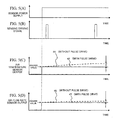
- FIG. 5 is a diagram showing the output signals of the air temperature sensor 11 and air flow rate sensors 5 to 10 upon the application of operating power in a case where those sensors are integrated with each other as with the sensing element 1 shown in FIG. 2.
- FIG. 5(A) shows an output waveform when the output voltage from the power supply of the temperature sensor 11 is successively made constant.
- FIG. 5(B) shows an output waveform when the output voltage from the power supply of the temperature sensor 11 is made pulsative.
- FIG. 5(C) shows the output signal waveforms of the temperature sensor when the power supply output voltage is successively made constant and when it is made pulsative.
- FIG. 5(D) shows the output signal waveforms of the air flow rate sensor when the power supply output voltage is successively made constant and when it is made pulsative.
- the air temperature sensor 11 cannot sense an air temperature accurately due to its self-heating by the constant power supply voltage.
- the temperature sensor 11 is formed on the diaphragm 25 for the purpose of improving the response as shown in FIGS. 2 and 3, the heat capacity is small, so the temperature rise by the self-heating becomes significant.
- the sensing signal of the air flow rate sensor neighboring the downstream side of air flow also deviates from a proper value to have an error as indicated by a broken line 46.
- the air flow rate sensor constituted of a resistance element whose resistance value varies according to ambient temperature, is susceptive to the thermal effect generated from the temperature sensor 11.
- a pulse signal is supplied to the air temperature sensor 11 to sense an air temperature, thereby reducing the self-heating of the temperature sensor 11.
- the output of the temperature sensor 11 and that of the air flow rate sensor 3 are approximately identical to a proper value as indicated by solid lines 45 and 47 shown in FIGS. 5(C) and 5(D), respectively, thus allowing a highly accurate measurement.
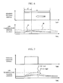
- FIG. 6 is a diagram showing the self-heating of the air temperature sensor 11 caused by the applying time period of the sensing pulse signal applied to the air temperature sensor 11.
- the output of the air temperature sensor 11 has a large sensing error due to the gradual self-heating as indicated by a broken line 48.
- the air flow rate sensor 3 is subjected to more influence.
- This pulse time period is preferably set to a value smaller than the thermal time constant of the temperature sensor 11.
- the pulse applying cycle time of the air temperature sensing pulse signal may be longer than that of the air flow rate sensing pulse signal. If so, the burden of the sensing circuit can be reduced.
- FIG. 7 is a diagram showing how the self-heating of the temperature sensor 11 is dependent on air flow rate.
- the second embodiment of the present invention is an example in which the pulse time period of the pulse signal supplied to the air temperature sensor 11 is varied according to air flow rate, thereby varying a duty ratio.
- FIG. 8 is a schematic configuration diagram of a sensing section of an air flowmeter according to the second embodiment of the present invention.
- the second embodiment has a circuit configuration approximately similar to that shown in FIG. 1, and is different in that the duty ratio of a pulse signal outputted by the sensing signal source 19 is varied according to a signal outputted from a PWM (pulse width modulation) circuit 52 based on an air flow rate signal generated by the air flow rate signal adjusting section 20.
- PWM pulse width modulation
- the pulse time period of the pulse sensing signal for driving the temperature sensor 11 is varied according to air flow rate.
- an optimum pulse time period of the air temperature sensing signal can be set according to air flow rate. Specifically, a pulse width employed when the air flow rate is small can be made smaller than that employed when the air flow rate is large. In other words, a duty ratio employed when the air flow rate is small is made larger than that employed when the air flow rate is large.
- the duty ratio is preferably equal to or less than 50 % and as small as possible in view of the self-heating of the temperature sensor 11. In view of the response, however, while being equal to or less than 50 %, the duty ratio is preferably as large as possible.
- the pulse width is increased up to a limit which is determined by the relationship with the self-heating of the air temperature sensor 11.
- the lower limit of the pulse width is approximately 1 ⁇ sec in view of the response; in view of self-heating, the upper limit is a width in which the duty ratio is equal to or less than 50 %.
- the temperature sensing sensor 11 can sense a higher temperature than the actual air temperature under the thermal effect from the engine.
- the temperature effect from the engine also varies depending on the air flow rate flowing through the air passage pipe, thereby causing a problem of making it difficult to sense an air temperature accurately.
- FIG. 9 is a schematic sectional diagram in a state where the air flowmeter of the present invention is actually used.
- an air flowmeter 60 is inserted into an air passage pipe 61 (intake air pipe) to be mounted and secured to the air passage pipe 61 by a flange 59.
- a circuit board 56 having a sensing element 1 and circuit element 57 mounted thereon.
- Air flow 62 flowing through the intake air pipe 61, is distributed into the air flowmeter 60 by an air intake port 53, bypassed via a bypass passage 54 to pass on a sensing element 1, and returned to the main passage pipe 61 from a bypass exit port 55.
- heat generated by the engine can reach the air flowmeter 60 through the passage pipe 61, giving a temperature effect to the sensing element 1.
- FIG. 10 is a diagram showing the output characteristic of the air temperature sensor 11 relative to air flow rate.
- a sensing signal 65 solid line of the air temperature sensor 11 gets closer to the air passage pipe temperature 64 in the low flow rate side, and to the suction air temperature 63 in the high flow rate side.
- a correction based on air flow rate is applied to the air temperature signal in the air temperature signal adjusting section 21 by use of the air flow rate signal sensed and adjusted by the air flow rate signal adjusting section 20. Accordingly, such flow rate dependence of the air temperature sensor 11 can be corrected.
- FIG. 11 is a diagram showing a third embodiment of the present invention.
- the third embodiment is an example in which the present invention is applied to an engine control system, and the correction of the air flow rate dependence of the air temperature sensor 11 in the first embodiment is made by a computer (ECU) 65 in the engine control system.
- ECU computer
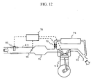
- FIG. 12 is a schematic diagram showing an overall configuration of an engine control system according to the third embodiment.
- an air flowmeter 60 is attached to an air passage pipe 61; intake air is supplied to an engine 72 via an intake manifold 71; the amount of air supplied to the engine 72 is adjusted by a throttle valve 70.
- Exhaust gas from the engine 72 is emitted via an exhaust air duct 73.
- Part of the exhaust gas from the exhaust air duct 73 is cooled by an EGR 74 and circulated to the engine 72; recirculation is controlled by an EGR valve 75.
- an ECU 76 Based on an output signal from the air flowmeter 60, an ECU 76 controls the opening of the throttle valve 70 and the operation of the engine 72 to have an optimum air oil ratio.
- the ECU 76 controls the opening and closing of the EGR valve 75 to have an optimum recirculation of exhaust gas.
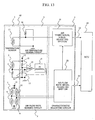
- FIG. 13 is a schematic configuration diagram of a sensing section of an air flowmeter according to a fourth embodiment of the present invention.
- the fourth embodiment supplies not a pulse signal but a direct current to the temperature sensor 11.
- no pulse signal source 19 is provided.
- Other constituent parts of the example shown in FIG. 13 are similar to those of the example shown in FIG. 11.
- the temperature sensor 11 is self-heated; the self-heating causes a sensed temperature to have an error.
- the air temperature sensing signal f (T) is expressed by the following equation (1).
- f ( T ) ( aT b + c ) / f ( q ) + d
- a, b, c, and d are constants and can be predetermined for each air flowmeter.
- the air temperature signal is a function of air flow rate.
- the above equation (2) is calculated in the air temperature adjusting section 21, and the air flow rate is corrected by use of the calculated proper value.
- a temperature sensing error caused by the self-heating of the temperature sensor 11 can be corrected.
- the present invention can be applied not only to an apparatus for measuring an air flow rate supplied to the engine of an automobile but also to other devices and systems.
- the present invention can be applied to apparatuses for sensing an air flow rate and air temperature, including an apparatus for an airplane or ship for sensing the flow rate of a medium other than air, such as hydrogen, which must have a high reliability.
- the heating resistance 5 of the air flow rate sensing circuit 3 can be driven by a direct-current voltage source, or can alternatively be driven by a pulse signal source.
- the present invention can be applied not only to an air flowmeter but also to an apparatus for measuring the flow rate of other gases (hydrogen, oxygen, nitrogen gas, and so on).
Landscapes
- Physics & Mathematics (AREA)
- Fluid Mechanics (AREA)
- General Physics & Mathematics (AREA)
- Measuring Volume Flow (AREA)
- Electrical Control Of Air Or Fuel Supplied To Internal-Combustion Engine (AREA)
- Combined Controls Of Internal Combustion Engines (AREA)
Applications Claiming Priority (1)
| Application Number | Priority Date | Filing Date | Title |
|---|---|---|---|
| JP2004327275A JP2006138688A (ja) | 2004-11-11 | 2004-11-11 | 流体流量計及びそれを用いたエンジン制御システム |
Publications (1)
| Publication Number | Publication Date |
|---|---|
| EP1657532A1 true EP1657532A1 (fr) | 2006-05-17 |
Family
ID=35515605
Family Applications (1)
| Application Number | Title | Priority Date | Filing Date |
|---|---|---|---|
| EP05018073A Withdrawn EP1657532A1 (fr) | 2004-11-11 | 2005-08-19 | Détecteur thermique de débit massique |
Country Status (3)
| Country | Link |
|---|---|
| US (1) | US20060096305A1 (fr) |
| EP (1) | EP1657532A1 (fr) |
| JP (1) | JP2006138688A (fr) |
Cited By (3)
| Publication number | Priority date | Publication date | Assignee | Title |
|---|---|---|---|---|
| EP2341214A1 (fr) * | 2009-12-29 | 2011-07-06 | Welltec A/S | Outil de journalisation de la thermographie |
| CN102128654A (zh) * | 2011-01-18 | 2011-07-20 | 蔡茂林 | 一种工业气体管道非介入式流量测量装置 |
| EP2789995B1 (fr) * | 2013-04-09 | 2019-05-22 | Honeywell International Inc. | Détecteur de débit à sortie linéaire améliorée |
Families Citing this family (10)
| Publication number | Priority date | Publication date | Assignee | Title |
|---|---|---|---|---|
| JP4850105B2 (ja) * | 2007-03-23 | 2012-01-11 | 日立オートモティブシステムズ株式会社 | 熱式流量計 |
| JP2008292361A (ja) * | 2007-05-25 | 2008-12-04 | Denso Corp | 流量測定装置 |
| WO2014141162A1 (fr) * | 2013-03-15 | 2014-09-18 | Coolit Systems, Inc. | Capteurs, techniques de communication multiplexée et systèmes associés |
| JP2014032040A (ja) * | 2012-08-01 | 2014-02-20 | Keumyang Ind Co Ltd | 船舶用内燃機関のピストン冷却オイルの流量及び温度感知のための熱量式流量感知及び温度計測システム |
| US12366870B2 (en) * | 2013-03-15 | 2025-07-22 | Coolit Systems, Inc. | Flow-path controllers and related systems |
| JP5791759B1 (ja) | 2014-05-19 | 2015-10-07 | 三菱電機株式会社 | 流量測定装置 |
| JP6434238B2 (ja) * | 2014-07-08 | 2018-12-05 | アズビル株式会社 | 流量計および補正値算出方法 |
| JP5933782B1 (ja) | 2015-03-16 | 2016-06-15 | 三菱電機株式会社 | 流量測定装置に一体に設けられた物理量測定装置および物理量測定方法 |
| US11452243B2 (en) | 2017-10-12 | 2022-09-20 | Coolit Systems, Inc. | Cooling system, controllers and methods |
| US12200914B2 (en) | 2022-01-24 | 2025-01-14 | Coolit Systems, Inc. | Smart components, systems and methods for transferring heat |
Citations (5)
| Publication number | Priority date | Publication date | Assignee | Title |
|---|---|---|---|---|
| JPS6036916A (ja) | 1983-08-10 | 1985-02-26 | Automob Antipollut & Saf Res Center | 熱式流量計 |
| JPH06249693A (ja) | 1993-02-25 | 1994-09-09 | Robert Bosch Gmbh | 質量流量センサおよびその製造方法 |
| JP2001324364A (ja) * | 2000-05-15 | 2001-11-22 | Hitachi Ltd | 熱式空気流量測定装置とその流量計及びそれを用いた内燃機関並びに熱式空気流量測定方法 |
| US6412471B1 (en) * | 1999-04-22 | 2002-07-02 | Visteon Global Technologies, Inc. | Throttle body system with integrated electronics |
| EP1441206A1 (fr) * | 2003-01-16 | 2004-07-28 | Dwyer Instruments, Inc. | Contrôle de temperature d'un capteur dans un anemomètre thermique |
Family Cites Families (9)
| Publication number | Priority date | Publication date | Assignee | Title |
|---|---|---|---|---|
| JPH06273208A (ja) * | 1993-03-24 | 1994-09-30 | Ricoh Co Ltd | 流量センサ |
| JP3364115B2 (ja) * | 1997-07-03 | 2003-01-08 | 三菱電機株式会社 | 感熱式流量検出素子 |
| EP2163889A1 (fr) * | 1999-02-03 | 2010-03-17 | Denso Corporation | Dispositif de mesure de la concentration d'un gaz avec compensation d'erreurs du signal de sortie |
| JP3461469B2 (ja) * | 1999-07-27 | 2003-10-27 | 株式会社日立製作所 | 熱式空気流量センサ及び内燃機関制御装置 |
| DE19960429A1 (de) * | 1999-12-15 | 2001-07-05 | Draeger Medizintech Gmbh | Vorrichtung und Verfahren zur Messung der Tempertaur eines Fluids |
| JP2002296121A (ja) * | 2001-04-02 | 2002-10-09 | Mitsuteru Kimura | 温度測定装置 |
| JP3955747B2 (ja) * | 2001-08-22 | 2007-08-08 | 三菱電機株式会社 | 流量測定装置 |
| JP2003240620A (ja) * | 2002-02-20 | 2003-08-27 | Hitachi Ltd | 気体流量測定装置 |
| JP2004205283A (ja) * | 2002-12-24 | 2004-07-22 | Hitachi Ltd | 流体流量検知装置 |
-
2004
- 2004-11-11 JP JP2004327275A patent/JP2006138688A/ja active Pending
-
2005
- 2005-08-19 US US11/206,733 patent/US20060096305A1/en not_active Abandoned
- 2005-08-19 EP EP05018073A patent/EP1657532A1/fr not_active Withdrawn
Patent Citations (6)
| Publication number | Priority date | Publication date | Assignee | Title |
|---|---|---|---|---|
| JPS6036916A (ja) | 1983-08-10 | 1985-02-26 | Automob Antipollut & Saf Res Center | 熱式流量計 |
| JPH06249693A (ja) | 1993-02-25 | 1994-09-09 | Robert Bosch Gmbh | 質量流量センサおよびその製造方法 |
| US5452610A (en) * | 1993-02-25 | 1995-09-26 | Robert Bosch Gmbh | Mass-flow sensor |
| US6412471B1 (en) * | 1999-04-22 | 2002-07-02 | Visteon Global Technologies, Inc. | Throttle body system with integrated electronics |
| JP2001324364A (ja) * | 2000-05-15 | 2001-11-22 | Hitachi Ltd | 熱式空気流量測定装置とその流量計及びそれを用いた内燃機関並びに熱式空気流量測定方法 |
| EP1441206A1 (fr) * | 2003-01-16 | 2004-07-28 | Dwyer Instruments, Inc. | Contrôle de temperature d'un capteur dans un anemomètre thermique |
Non-Patent Citations (1)
| Title |
|---|
| PATENT ABSTRACTS OF JAPAN vol. 2002, no. 03 3 April 2002 (2002-04-03) * |
Cited By (5)
| Publication number | Priority date | Publication date | Assignee | Title |
|---|---|---|---|---|
| EP2341214A1 (fr) * | 2009-12-29 | 2011-07-06 | Welltec A/S | Outil de journalisation de la thermographie |
| WO2011080290A1 (fr) * | 2009-12-29 | 2011-07-07 | Dkwelltec A/S | Outil de diagraphie thermographique |
| CN102128654A (zh) * | 2011-01-18 | 2011-07-20 | 蔡茂林 | 一种工业气体管道非介入式流量测量装置 |
| CN102128654B (zh) * | 2011-01-18 | 2014-07-09 | 北京航空航天大学 | 一种工业气体管道非介入式流量测量装置 |
| EP2789995B1 (fr) * | 2013-04-09 | 2019-05-22 | Honeywell International Inc. | Détecteur de débit à sortie linéaire améliorée |
Also Published As
| Publication number | Publication date |
|---|---|
| JP2006138688A (ja) | 2006-06-01 |
| US20060096305A1 (en) | 2006-05-11 |
Similar Documents
| Publication | Publication Date | Title |
|---|---|---|
| CN100414263C (zh) | 加热式空气流量计 | |
| EP1657532A1 (fr) | Détecteur thermique de débit massique | |
| EP1698864B1 (fr) | Debitmetre thermique pour fluides | |
| JP4157034B2 (ja) | 熱式流量計測装置 | |
| KR20050047079A (ko) | 공용 기준 레그를 갖는 가변 저항기 센서 | |
| US4872339A (en) | Mass flow meter | |
| WO1995014215A1 (fr) | Procede et dispositif destines a detecter le debit d'air d'aspiration pour un moteur | |
| EP1431717A1 (fr) | Instrument de mesure de debit | |
| US20050075804A1 (en) | Optimized convection based mass airflow sensor circuit | |
| US7287424B2 (en) | Thermal type flow measurement apparatus having asymmetrical passage for flow rate measurement | |
| US6230559B1 (en) | Thermal type flow measuring instrument and temperature-error correcting apparatus thereof | |
| JP3981907B2 (ja) | 流量測定装置 | |
| JP2003302271A (ja) | 流量測定部パッケージ及びそれを用いた流量測定ユニット | |
| US7251995B2 (en) | Fluid flow sensor | |
| US7047805B2 (en) | Fluid flow meter having an auxiliary flow passage | |
| JP2005308665A (ja) | 発熱抵抗体式流量計 | |
| JP3200005B2 (ja) | 発熱抵抗式空気流量測定装置 | |
| JPS61239119A (ja) | 空気流量検出器 | |
| JP2009031014A (ja) | 熱式ガス質量流量計 | |
| JP2003279395A (ja) | 流量測定方法及び流量計 | |
| JP4914226B2 (ja) | 気体流量計 | |
| JP3064086B2 (ja) | 空気流量計及びこれを用いたエンジン制御システム | |
| JPH11351930A (ja) | 発熱抵抗体式空気流量計 | |
| JP3473501B2 (ja) | 熱式空気流量計 | |
| JP3133617B2 (ja) | 熱式空気流量検出装置 |
Legal Events
| Date | Code | Title | Description |
|---|---|---|---|
| PUAI | Public reference made under article 153(3) epc to a published international application that has entered the european phase |
Free format text: ORIGINAL CODE: 0009012 |
|
| AK | Designated contracting states |
Kind code of ref document: A1 Designated state(s): AT BE BG CH CY CZ DE DK EE ES FI FR GB GR HU IE IS IT LI LT LU LV MC NL PL PT RO SE SI SK TR |
|
| AX | Request for extension of the european patent |
Extension state: AL BA HR MK YU |
|
| 17P | Request for examination filed |
Effective date: 20061117 |
|
| 17Q | First examination report despatched |
Effective date: 20061219 |
|
| AKX | Designation fees paid |
Designated state(s): DE |
|
| STAA | Information on the status of an ep patent application or granted ep patent |
Free format text: STATUS: THE APPLICATION IS DEEMED TO BE WITHDRAWN |
|
| 18D | Application deemed to be withdrawn |
Effective date: 20110301 |