EP1657773A1 - Generateur a pile a combustible a electrolyte solide - Google Patents
Generateur a pile a combustible a electrolyte solide Download PDFInfo
- Publication number
- EP1657773A1 EP1657773A1 EP04748267A EP04748267A EP1657773A1 EP 1657773 A1 EP1657773 A1 EP 1657773A1 EP 04748267 A EP04748267 A EP 04748267A EP 04748267 A EP04748267 A EP 04748267A EP 1657773 A1 EP1657773 A1 EP 1657773A1
- Authority
- EP
- European Patent Office
- Prior art keywords
- fuel cell
- solid electrolyte
- solid
- fuel
- flame
- Prior art date
- Legal status (The legal status is an assumption and is not a legal conclusion. Google has not performed a legal analysis and makes no representation as to the accuracy of the status listed.)
- Withdrawn
Links
Images


Classifications
-
- H—ELECTRICITY
- H01—ELECTRIC ELEMENTS
- H01M—PROCESSES OR MEANS, e.g. BATTERIES, FOR THE DIRECT CONVERSION OF CHEMICAL ENERGY INTO ELECTRICAL ENERGY
- H01M8/00—Fuel cells; Manufacture thereof
- H01M8/04—Auxiliary arrangements, e.g. for control of pressure or for circulation of fluids
- H01M8/04007—Auxiliary arrangements, e.g. for control of pressure or for circulation of fluids related to heat exchange
- H01M8/04014—Heat exchange using gaseous fluids; Heat exchange by combustion of reactants
- H01M8/04022—Heating by combustion
-
- H—ELECTRICITY
- H01—ELECTRIC ELEMENTS
- H01M—PROCESSES OR MEANS, e.g. BATTERIES, FOR THE DIRECT CONVERSION OF CHEMICAL ENERGY INTO ELECTRICAL ENERGY
- H01M8/00—Fuel cells; Manufacture thereof
- H01M8/06—Combination of fuel cells with means for production of reactants or for treatment of residues
- H01M8/0606—Combination of fuel cells with means for production of reactants or for treatment of residues with means for production of gaseous reactants
- H01M8/0612—Combination of fuel cells with means for production of reactants or for treatment of residues with means for production of gaseous reactants from carbon-containing material
- H01M8/0643—Gasification of solid fuel
-
- H—ELECTRICITY
- H01—ELECTRIC ELEMENTS
- H01M—PROCESSES OR MEANS, e.g. BATTERIES, FOR THE DIRECT CONVERSION OF CHEMICAL ENERGY INTO ELECTRICAL ENERGY
- H01M8/00—Fuel cells; Manufacture thereof
- H01M8/10—Fuel cells with solid electrolytes
- H01M8/12—Fuel cells with solid electrolytes operating at high temperature, e.g. with stabilised ZrO2 electrolyte
- H01M8/1231—Fuel cells with solid electrolytes operating at high temperature, e.g. with stabilised ZrO2 electrolyte with both reactants being gaseous or vaporised
-
- Y—GENERAL TAGGING OF NEW TECHNOLOGICAL DEVELOPMENTS; GENERAL TAGGING OF CROSS-SECTIONAL TECHNOLOGIES SPANNING OVER SEVERAL SECTIONS OF THE IPC; TECHNICAL SUBJECTS COVERED BY FORMER USPC CROSS-REFERENCE ART COLLECTIONS [XRACs] AND DIGESTS
- Y02—TECHNOLOGIES OR APPLICATIONS FOR MITIGATION OR ADAPTATION AGAINST CLIMATE CHANGE
- Y02E—REDUCTION OF GREENHOUSE GAS [GHG] EMISSIONS, RELATED TO ENERGY GENERATION, TRANSMISSION OR DISTRIBUTION
- Y02E60/00—Enabling technologies; Technologies with a potential or indirect contribution to GHG emissions mitigation
- Y02E60/30—Hydrogen technology
- Y02E60/50—Fuel cells
Definitions
- the present invention relates to a power generating apparatus using a solid electrolyte fuel cell and, more particularly, to a power generating apparatus using a solid electrolyte fuel cell that can generate power utilizing a flame produced by burning a solid fuel and that is easy to handle for storage, transport, etc., wherein the solid electrolyte fuel cell is fabricated by forming a cathode layer and an anode layer on a solid electrolyte substrate and by employing a simple structure that does not require hermetic sealing and thereby achieving a compact and thin construction.
- fuel cells have been developed and commercially implemented as low-pollution power generating means to replace traditional power generating means such as thermal power generation, or as electric energy sources for electric vehicles that replace traditional engines, which use gasoline or the like as the fuel, with electric motors.
- traditional power generating means such as thermal power generation
- electric energy sources for electric vehicles that replace traditional engines, which use gasoline or the like as the fuel, with electric motors.
- Fuel cells can be classified into various types according to the method of power generation, one being the type of fuel cell that uses a solid electrolyte.
- a calcined structure made of yttria(Y 2 O 3 )-doped stabilized zirconia is used as an oxygen ion conducting solid electrolyte layer.
- This fuel cell comprises a cathode layer formed on one surface of the solid electrolyte layer and an anode layer on the opposite surface thereof, and oxygen or an oxygen-containing gas is fed to the cathode layer, while a fuel gas such as methane is fed to the anode layer.
- the oxygen (O 2 ) fed to the cathode layer is converted into oxygen ions (O 2- ) at the boundary between the cathode layer and the solid electrolyte layer, and the oxygen ions are conducted through the solid electrolyte layer into the anode layer where the ions react with the fuel gas, for example, a methane gas (CH 4 ), fed to the anode layer, producing water (H 2 O), carbon dioxide (CO 2 ), hydrogen (H 2 ), and carbon monoxide (CO).
- the oxygen ions release electrons, and a potential difference therefore occurs between the cathode layer and the anode layer.
- the cathode layer and the anode layer are electrically connected by a lead wire, the electrons in the anode layer flow into the cathode layer via the lead wire, and the fuel cell thus generates electricity.
- the operating temperature of this fuel cell is about 1,000°C.
- this type of fuel cell requires the provision of separate chambers, one being an oxygen or oxygen-containing gas supply chamber on the cathode layer side and the other a fuel gas supply chamber on the anode layer side; furthermore, as the fuel cell is exposed to oxidizing and reducing atmospheres at high temperatures, it has been difficult to increase the durability of the fuel cell.
- a fuel cell of the type that comprises a cathode layer and an anode layer formed on opposite surfaces of a solid electrolyte layer, and that generates an electromotive force between the cathode layer and the anode layer by placing the fuel cell in a fuel gas mixture consisting of a fuel gas, for example, a methane gas, and an oxygen gas.
- a fuel gas for example, a methane gas, and an oxygen gas.
- the principle of generating an electromotive force between the cathode layer and the anode layer in this type of fuel cell is the same as that for the above-described separate-chamber type fuel cell but, as the entire fuel cell can be placed in substantially the same atmosphere, the fuel cell can be constructed as a single-chamber type cell to which the fuel gas mixture is supplied, and the durability of the fuel cell can be increased.
- the above proposed fuel-cell battery is of the type that is constructed by housing individual fuel cells in a single chamber; on the other hand, there has been proposed an apparatus that generates power by placing a solid electrolyte fuel cell in or near a flame and thereby holding the solid electrolyte fuel cell at its operating temperature.
- Such a power generating apparatus is proposed, for example, in Japanese Unexamined Patent Publication No. H06-196176.
- the above-described power generating apparatus employs a solid electrolyte fuel cell of the type that directly utilizes a flame; this type of fuel cell has the characteristic of being an open type, the solid electrolyte fuel cell not needing to be housed in a hermetically sealed container.
- this type of fuel cell can reduce the startup time, is simple in structure, and is therefore advantageous when it comes to reducing the size, weight, and cost of the fuel cell.
- this type of fuel cell can be incorporated in a conventional combustion apparatus or an incinerator or the like, and is thus expected to be used as a power supply apparatus.
- the present invention provides a power generating apparatus, using a solid electrolyte fuel cell, wherein the solid electrolyte fuel cell is fabricated by forming a cathode layer on one surface of a flat plate-like solid electrolyte substrate and an anode layer on a surface thereof opposite to the one surface, and a solid fuel is placed below the solid electrolyte fuel cell, and wherein the power generating apparatus generates power by supplying a flame produced by combustion of the solid fuel to the anode layer, while supplying air to the cathode layer; here, a wood material, a solid fuel made of paraffin, or a solid fuel made of alcohol is used as the solid fuel.
- air is supplied to a burning portion of the solid fuel, and the solid fuel is placed inside a combustion apparatus having an opening through which the flame is supplied to the anode layer, wherein the combustion apparatus has an air intake opening.
- the combustion apparatus further comprises a heating means for heating the solid fuel and an air supply means for supplying air into the combustion apparatus, wherein the solid fuel is burned in the presence of the air to produce a volatile compound, and the flame produced by combustion of the volatile compound is supplied to the solid electrolyte fuel cell.
- Figures 1A and 1B are diagrams for explaining an embodiment of a power generating apparatus using a solid electrolyte fuel cell according to the present invention.
- Figures 2A and 2B are diagrams for explaining another embodiment of a power generating apparatus using a solid electrolyte fuel cell according to the present invention.
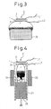
- Figure 3 is a diagram for explaining still another embodiment of a power generating apparatus using a solid electrolyte fuel cell according to the present invention.
- Figure 4 is a diagram for explaining an embodiment in which the production of a flame is improved in a power generating apparatus using a solid electrolyte fuel cell according to the present invention.
- Figures 5A and 5B are schematic diagrams for explaining the structures of prior art solid electrolyte fuel-cell batteries that use a fuel gas mixture.
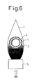
- Figure 6 is a diagram for explaining the structure of a prior art solid electrolyte fuel cell that uses a flame.
- Embodiments of a power generating apparatus using a solid electrolyte fuel cell according to the present invention will be described below with reference to the drawings.
- prior art solid electrolyte fuel cells which provide the basis for the power generating apparatus using the solid electrolyte fuel cell according to the present invention, will be described in order to clarify the features and advantages of the present embodiment.
- FIGs 5A and 5B show the structures of the single-chamber fuel-cell batteries proposed in the prior art.
- the fuel-cell battery shown in Figure 5A has a structure in which individual fuel cells each containing a solid electrolyte layer are stacked one on top of another with each cell oriented parallel to the flow direction of the fuel gas mixture.
- Each fuel cell comprises a solid electrolyte layer 1 of a closely compacted structure and a cathode layer 2 and an anode layer 3 as porous layers formed on opposite surfaces of the solid electrolyte layer 1, and the plurality of fuel cells C1 to C4 of identical structure are stacked in a ceramic container 4. Then, the fuel cells are hermetically sealed in the container 4 by adding packing fillers 7 and 8 and closing the container with end plates 9 and 10.
- the container 4 is provided with a supply pipe 5 for supplying the fuel gas mixture containing oxygen and a fuel such as methane and an exhaust pipe 6 for removing the exhaust gas.
- Vacant spaces in the container 4, where the fuel gas mixture and the exhaust gas flow i.e., the areas in the container 4 other than the area occupied by the fuel cells, are filled with the fillers 7 and 8, and a suitable gap is provided therebetween; therefore, when the fuel-cell battery is operated, if a fuel gas mixture within the ignitability limit is present, the fuel gas mixture does not ignite.
- each fuel cell comprises a solid electrolyte layer 1 of a porous structure and a cathode layer 2 and an anode layer 3 as porous layers formed on opposite surfaces of the solid electrolyte layer 1, and the plurality of fuel cells C1 to C5 of identical structure are stacked in the container 4.
- a power generating apparatus using a fuel cell that is not housed in a single chamber but directly utilizes a flame, as previously described, is shown in Figure 6.
- the fuel cell used in the power generating apparatus shown in Figure 6 comprises a zirconia solid electrolyte layer 1 formed in a tubular structure, an anode layer 3 as a fuel electrode formed on the outer circumference of the tubular structure, and a cathode layer 2 as an air electrode formed on the inner circumference of the tubular structure.
- This solid electrolyte fuel cell is placed with its anode layer 3 exposed to a reducing flame portion of a flame f generated from a combustion apparatus 5 to which the fuel gas is supplied.
- radical components, etc. present in the reducing flame are utilized as the fuel, while air is supplied by convection or diffusion to the cathode layer 2 inside the tubular structure, and the fuel cell thus generates power.
- Figures 1A and 1B show the structure of the power generating apparatus using the solid electrolyte fuel cell according to the present embodiment.
- Figure 1A shows a vertical cross-sectional view of the power generating apparatus
- Figure 1B shows a vertical cross-sectional view as viewed from a direction at right angles to the direction of view in Figure 1A.
- the solid electrolyte fuel cell used in the power generating apparatus of the present embodiment employs a solid electrolyte layer formed in the shape of a plate, for example, a thin plate-like solid electrolyte substrate.
- a cathode layer (air electrode layer) and an anode layer (fuel electrode layer) are respectively formed on opposite surfaces of the solid electrolyte substrate, and a solid fuel supplied below the anode layer is burned so that the flame is applied over the entire surface of the anode layer.
- a readily available solid fuel such as a wood material, wood chips or pellets, paraffin, olefin, alcohol, etc. can be used as the solid fuel here.
- the solid electrolyte fuel cell C used in the power generating apparatus of the present embodiment comprises the flat plate-like solid electrolyte substrate 1 and the cathode layer 2 (air electrode layer) and anode layer 3 (fuel electrode layer) formed on opposite surfaces of the solid electrolyte substrate 1, and electromotive force extracting lead wires L1 and L2 are attached to the cathode layer 2 and the anode layer 3, respectively.
- the solid electrolyte fuel cell C is placed above a combustion apparatus 11.
- the combustion apparatus 11 has a combustion chamber that can accommodate the solid fuel 13 therein, and a holder 12 such as a grate for holding the solid fuel is provided inside the combustion chamber.
- a wood material is supplied as the solid fuel.
- a flame opening 14 which supports the fuel cell C, and through which the anode layer 3 of the fuel cell C is exposed to the flame produced in the combustion chamber.
- a solid fuel supply opening 15 through which the solid fuel 13 is supplied into the combustion chamber, while an air intake opening 16 through which air is supplied is formed below the solid fuel holder 12.
- the solid fuel 13 is supplied into the combustion chamber of the combustion apparatus 11, and the flame f is produced by the combustion of the solid fuel.
- the flame f thus produced is applied over the anode layer 3 of the solid electrolyte fuel cell C that faces the opening 14, while the outside air is fed to the cathode layer 2.
- the radical components in the flame react with the oxygen in the air, generating an electromotive force between the lead wires L1 and L2, and the apparatus thus functions as a power generating apparatus using the solid electrolyte fuel cell.
- the flame generating conditions are chosen so that the flame f produced by the combustion is uniformly applied over the entire surface of the anode layer 3 and so that the radical components in the flame are fed to the anode layer in an optimum condition.
- the solid electrolyte fuel cell C of the present embodiment is formed in a flat plate-like structure, with the cathode layer 2 formed on one surface of the solid electrolyte substrate 1 and the anode layer 3 on the opposite surface thereof.
- the cathode layer 2 and the anode layer 3 are formed in this way, when the anode layer 3 is disposed so as to face the side exposed to the flame f produced by the combustion of the solid fuel 13, then it follows that the cathode layer 2 is disposed so as to face the atmosphere.
- the flame can be applied uniformly compared with the tubular type solid electrolyte fuel cell shown in Figure 6; furthermore, as the anode layer 3 is disposed so as to face the flame side, hydrocarbons, hydrogen, radicals (OH, CH, C 2 , O 2 H, CH 3 ), etc. present in the flame can be easily utilized as the fuel.
- the flat plate-like structure has the further effect of being able to completely block the flame and, when the anode layer 3 is placed facing the flame side, then the cathode layer 2 is exposed to the atmosphere, as shown in Figures 1A and 1B.
- an oxygen-containing gas air, oxygen-rich gas, etc.
- the fuel cell C is disposed above the solid fuel 13 and, more preferably, the fuel cell C is disposed so that the anode layer 3 is exposed to the reducing flame near the base of the flame.
- the anode layer 3 is disposed so as to be exposed to the reducing flame, hydrocarbons, hydrogen, radicals, etc. present in the reducing flame can be efficiently utilized as the fuel; furthermore, the anode layer can be used in a good condition even if it easily tends to degrade due to oxidation, and the durability can thus be maintained.
- solid electrolyte substrate For the solid electrolyte substrate 1, known materials can be used, examples including the following:
- anode layer 3 known materials can be used, examples including the following:
- the sintered material composed principally of electrically conductive oxide given in e) has excellent oxidation resistance, and therefore, can prevent a phenomena resulting from the oxidation of the anode layer, such as separation of the anode layer from the solid electrolyte layer and degradation of power generation efficiency or inability to generate power due to a rise in the electrode resistance of the anode layer.
- electrically conductive oxide lithium-dissolved nickel oxide is preferred. It will also be noted that a high power-generation performance can be obtained by adding a platinum-group metal or rhenium or its oxide to the material given in d) or e).
- lanthanum manganite doped with an element such as strontium (Sr), from group III of the periodic table (for example, lanthanum strontium manganite) and a lanthanum gallium oxide or cobalt oxide compound doped with such an element (for example, lanthanum strontium cobaltite).
- an element such as strontium (Sr)
- group III of the periodic table for example, lanthanum strontium manganite
- lanthanum gallium oxide or cobalt oxide compound doped with such an element for example, lanthanum strontium cobaltite
- the solid electrolyte substrate 1 of the solid electrolyte fuel cell C is formed in a porous structure.
- the solid electrolyte substrate 1 used in the present embodiment may be formed in a closely compacted structure, as in the prior art, but in that case, its thermal shock resistance would drop, and the substrate would tend to crack easily when subjected to abrupt temperature changes.
- the solid electrolyte layer generally is formed thicker than the anode layer or the cathode layer, any crack in the solid electrolyte layer would lead to the formation of cracks in the entire structure of the solid electrolyte fuel cell which would eventually disintegrate in pieces.
- the solid electrolyte substrate When the solid electrolyte substrate is formed in a porous structure, its thermal shock resistance increases, and defects such as cracking do not occur even when the substrate is subjected, during power generation, to abrupt temperature changes associated with the ignition or extinguishment of the flame or to a heat cycle involving rapid changes in temperature. Further, when the porous structure was fabricated with a porosity of less than 10%, no appreciable improvement in thermal shock resistance was observed, but when the porosity was 10% or higher, good thermal shock resistance was observed, and a better result was obtained when the porosity was increased to 20% or higher. This is presumably because, when the solid electrolyte layer is formed in a porous structure, thermal expansion due to heating is absorbed by the pores in the porous structure.
- the solid electrolyte fuel cell is fabricated, for example, in the following manner. First, powders of materials for forming the solid electrolyte layer are mixed in prescribed proportions, and the mixture is molded into a flat plate shape. After that, the flat plate structure is calcined and sintered to produce the substrate which functions as the solid electrolyte layer.
- the powder materials including a pore-forming agent and the calcination conditions such as calcination temperature, calcination time, preliminary calcination, etc., solid electrolyte layers with various porosities can be produced.
- a paste for forming the cathode layer is applied over one surface of the substrate thus obtained as the solid electrolyte layer, and a paste for forming the anode layer is applied over the other surface thereof; then, the entire structure is calcined to complete the fabrication of the solid electrolyte fuel cell.
- the durability of the solid electrolyte fuel cell can be further enhanced as will be described hereinafter.
- This durability enhancing technique involves embedding a metal mesh in, or fixing a metal mesh to, each of the cathode layer 2 and the anode layer 3 in the flat plate-like fuel cell C shown in Figures 1A and 1B.
- the material (paste) for forming each layer is applied over the solid electrolyte layer, and the metal mesh is embedded in the thus applied material, which is then calcined.
- the metal mesh is not completely embedded in each layer material but may be glued to it, followed by calcining.
- the metal mesh a material that has excellent heat resistance, and that well matches the thermal expansion coefficient of the cathode layer and anode layer which the metal mesh is to be embedded in or fixed to, is preferred.
- Specific examples include a platinum metal and a platinum-containing metal alloy formed in the shape of a mesh.
- stainless steel of SUS 300 series (304, 316, etc.) or SUS 400 series (430, etc.) may be used; these materials are advantageous in terms of cost.
- metal wires may be embedded in or fixed to the anode layer and the cathode layer.
- the metal wires are formed using the same metal material as that used for the metal mesh, and the number of wires and the configuration of the wire arrangement are not limited to any particular number or configuration.
- the metal meshes or metal wires embedded in or fixed to the anode layer and the cathode layer serve to reinforce the structure so that the solid electrolyte layer, if cracked due to its thermal history, etc., will not disintegrate into pieces; furthermore, the metal meshes or the metal wires act to electrically connect cracked portions.
- the above description has been given by dealing with the case where the solid electrolyte substrate is formed in a porous structure, but it will be recognized that a closely compacted structure can be employed for the solid electrolyte substrate of the fuel cell of the present embodiment; in that case, the metal meshes or the metal wires embedded in or fixed to the cathode layer and the anode layer provide particularly effective means to cope with the problem of cracking due to thermal history.
- the metal mesh or the metal wires may be provided in both the anode layer and the cathode layer or in either one of the layers. Further, the metal mesh and the metal wires may be used in combination. When the metal mesh or the metal wires are embedded at least in the anode layer, then if cracking occurs due to thermal history, the power generation performance of the fuel cell does not degrade and the fuel cell can continue to generate power. As the power generation performance of the solid electrolyte fuel cell is largely dependent on the effective area of the anode layer as the fuel electrode, the metal mesh or the metal wires should be provided at least at the anode layer.
- the solid electrolyte fuel cell having the above structure When the solid electrolyte fuel cell having the above structure is installed as the solid electrolyte fuel cell C in the power generating apparatus shown in Figures 1A and 1B, and is arranged so as to be exposed to the flame produced by the combustion of the solid fuel, then the fuel cell can be used as an open-type power generating means that does not require a hermetically sealed construction. Further, as the solid fuel is used as the flame supply source, the power generating apparatus is simple in construction and easy to store and transport and thus provides a handy means for power generation.
- This power generating apparatus is used advantageously for the generation of small amounts of power, and is suitable for use as a power supply for driving a load that does not require much current but for which a voltage is important.
- loads include, for example, LEDs, LCDs, portable radios, and portable information apparatuses, and the power generating apparatus can be used, for example, as an emergency power supply in the event of a power failure or as a power supply for outdoor activities.
- FIG. 1A and 1B show an example in which paraffin is used as the solid fuel.
- a candle can be given as an example of the solid fuel made of paraffin.
- the combustion apparatus 11 such as shown in Figures 1A and 1B is not shown in Figures 2A and 2B, but the power generating apparatus can also be achieved by just exposing the solid electrolyte fuel cell C to the flame of the candle.
- Figure 2A shows the condition in which the solid electrolyte fuel cell C with its anode layer 3 facing down is disposed above the candle 17 whose wick 18 is producing the flame.
- the position of the fuel cell C is adjusted so that the entire surface of the anode layer 3 will be exposed to the flame f produced by the wick 18.
- the radical components contained in the frame F can then be supplied effectively to the anode layer 3, and the radical components react with the oxygen in the air fed to the cathode layer 2, generating an electromotive force between the lead wires L1 and L2.
- Figure 2B shows the case where a candle is used as the solid fuel, as in the case of Figure 2A, but differs in that an end of a tube 19 extending from the bottom is disposed near the wick 18 of the candle 17.
- the combustion condition in the burning portion of the candle 17 can be changed, and the radical components in the flame f can thus be increased. This serves to enhance the power generation efficiency.
- Figures 2A and 2B have shown an example of the power generating apparatus that uses a candle as the solid fuel
- Figure 3 hereinafter given shows an example in which, instead of the candle, a solid fuel made of alcohol is used as the solid fuel for the power generating apparatus.
- This solid fuel compared with the candle, offers the advantages that the amount of soot can be reduced, that the flame f is stable, and that the area of the anode layer 3 can be increased; this not only allows the solid electrolyte fuel cell to be used over an extended period of time, but also serves to enhance the power generation efficiency.
- the substrate of the solid electrolyte fuel cell used in the power generating apparatus of the present embodiment should be formed in such a shape that the flame can be applied effectively over the entire surface of the anode layer.
- the solid electrolyte substrate can be formed in a circular shape that matches the shape of the anode layer.
- the fuel cell When it is desired to increase the power generation output, the fuel cell should be constructed using a larger-area solid electrolyte substrate, and the flame should be produced so as to match the size of the fuel cell. Further, when it is desired to increase the electromotive force of the fuel cell, the cathode layer and the anode layer formed on opposite sides of the solid electrolyte substrate should each be split into a plurality of segments, forming a plurality of fuel cell units each comprising a cathode layer segment and an anode layer segment thus split. Then, these fuel cell units can be connected in series by metal wires.
- the air intake opening 16 is formed in the lower part of the combustion apparatus 11 in the power generating apparatus shown in Figure 1B in which the flame produced by the combustion of the solid fuel is supplied to the solid electrolyte fuel cell.
- the air necessary for natural combustion of the solid fuel 13 is supplied through the air intake opening 16 into the combustion apparatus 11, that is, the air is introduced into the combustion apparatus 11 by natural convection.
- the air is supplied in this manner, the radical components in the flame that contribute to the power generation of the fuel cell can be produced or fuel species can be extracted from the solid fuel, but it is not possible to make adjustments to optimize the flame produced by the combustion so as to effectively contribute to the power generation of the fuel cell.
- an end of the tube 19 is disposed near the wick 18 of the candle 17.
- the combustion condition in the burning portion of the candle 17 can be changed, and the radical components in the flame f can thus be increased; this serves to enhance the power generation efficiency.
- the condition of the flame being produced by the flame can be optimized relatively easily by adjusting the supply of the air through the tube 19.
- volatile compounds account for about 80% of the amount of decrease and nonvolatile components account for about 19%.
- the nonvolatile components include tar, coke, etc.
- the volatile compounds extracted here are used as fuel species and burned to generate radical components.
- the radical components to be produced in the flame can be optimized by adjusting the amount of air necessary for the combustion of the volatile compounds.
- FIG 4 shows a specific example of the power generating apparatus which is adapted to use a wood material as the solid fuel and to supply to the fuel cell the flame produced by burning the volatile compounds generated from the wood pellets.
- the wood material 13 was simply placed on the grate 12 and was burned by the air supplied through the air intake opening 16.
- a heat resistant container 21 made of alumina ceramic or the like, which corresponds to the combustion apparatus is used, and a porous member 22 that serves as a substitute for the grate is placed in the lower part of the container, to form the combustion chamber.
- a heater 23, as a heating means, is provided around the outer circumference of the upper part of the heat resistant container 21. Then, the fuel cell C with its anode layer 3 facing down is placed over the opening in the top of the heat resistant container 21.
- the wood material 13 is placed on the porous member 22 inside the combustion chamber within the heat resistant container 21.
- the wood material 13 is heated by the heater 23, and air is supplied through the porous member 22 into the combustion chamber.
- the heater 23 is driven to heat the wood material 13 up to about 500°C.
- the flame f is produced by burning the volatile compounds generated from the wood material 13, and this flame f supplies the radical components to the anode layer 3 of the fuel cell C.
- the heating means is provided around the outer circumference of the combustion apparatus containing the solid fuel, and a suitable amount of air is supplied to the combustion chamber, volatile compounds that can be burned can be extracted effectively from the solid fuel without requiring the provision of a large-scale reformer.
- the flame produced by burning the volatile compounds can be applied to the fuel cell, and the amount of radical components to be supplied to the fuel cell can thus be increased, increasing the power generation output of the fuel cell.
- a substrate of samaria-doped ceria (SDC, Sm 0.2 Ce 0.8 O 1.9 ceramic) with a thickness of 200 ⁇ m was used as the solid electrolyte substrate.
- An SDC paste containing 50% by weight of Sm 0.5 Sr 0.5 CoO 3 was printed as a cathode layer on one surface of this ceramic substrate, and an SDC paste, to which Li-doped NiO 2 containing 5% by weight of Rh 2 O 3 was added in an amount of 40% by weight, was printed as an anode layer on the opposite surface thereof; then, the entire structure was calcined at 1200°C.
- the power generating apparatus using the solid electrolyte fuel cell shown in Figure 4 was fabricated in this example.
- a substrate of samaria-doped ceria (SDC, Sm 0.2 Ce 0.8 O 1.9 ceramic) with a thickness of 200 ⁇ m was used as the solid electrolyte substrate.
- An SDC paste containing 50% by weight of Sm 0.5 Sr 0.5 CoO 3 was printed as a cathode layer on one surface of this ceramic substrate, and an SDC paste, to which Li-doped NiO 2 containing 5% by weight of Rh 2 O 3 was added in an amount of 40% by weight, was printed as an anode layer on the opposite surface thereof; then, the entire structure was calcined at 1200°C.
- Wood pellets were used as the solid fuel to be supplied to the anode layer of the thus fabricated solid electrolyte fuel cell, and the pellets were heated by the heater while supplying air into the combustion chamber at a rate of 3000 cm 3 /minute.
- the flame produced by burning the volatile compounds extracted from the pellets was applied to the fuel cell, and the characteristics were evaluated. As a result, it was confirmed that the open-circuit voltage was 0.84 V and the output power density was 99 mW/cm 2 .
- the power generating apparatus was constructed by employing the solid electrolyte fuel cell comprising the cathode layer and the anode layer formed on opposite surfaces of the plate-like solid electrolyte substrate with provisions made to ensure that the flame produced by the combustion of the solid fuel is applied over the entire surface of the anode layer, power can be generated using a compact low-cost fuel cell that has high durability; furthermore, as a solid fuel is used, the power generating apparatus is easy to store and transport and thus provides a handy means for power generation.
Landscapes
- Engineering & Computer Science (AREA)
- Chemical & Material Sciences (AREA)
- Life Sciences & Earth Sciences (AREA)
- Manufacturing & Machinery (AREA)
- Sustainable Development (AREA)
- Sustainable Energy (AREA)
- Chemical Kinetics & Catalysis (AREA)
- Electrochemistry (AREA)
- General Chemical & Material Sciences (AREA)
- Combustion & Propulsion (AREA)
- Fuel Cell (AREA)
Applications Claiming Priority (2)
| Application Number | Priority Date | Filing Date | Title |
|---|---|---|---|
| JP2003208246 | 2003-08-21 | ||
| PCT/JP2004/011296 WO2005020364A1 (fr) | 2003-08-21 | 2004-07-30 | Generateur a pile a combustible a electrolyte solide |
Publications (2)
| Publication Number | Publication Date |
|---|---|
| EP1657773A1 true EP1657773A1 (fr) | 2006-05-17 |
| EP1657773A4 EP1657773A4 (fr) | 2008-08-13 |
Family
ID=34208968
Family Applications (1)
| Application Number | Title | Priority Date | Filing Date |
|---|---|---|---|
| EP04748267A Withdrawn EP1657773A4 (fr) | 2003-08-21 | 2004-07-30 | Generateur a pile a combustible a electrolyte solide |
Country Status (5)
| Country | Link |
|---|---|
| US (1) | US20060073366A1 (fr) |
| EP (1) | EP1657773A4 (fr) |
| JP (1) | JPWO2005020364A1 (fr) |
| CA (1) | CA2515611A1 (fr) |
| WO (1) | WO2005020364A1 (fr) |
Families Citing this family (2)
| Publication number | Priority date | Publication date | Assignee | Title |
|---|---|---|---|---|
| JP5361143B2 (ja) * | 2007-05-29 | 2013-12-04 | 新光電気工業株式会社 | 固体酸化物型燃料電池およびその製造方法 |
| US10847780B2 (en) | 2016-09-16 | 2020-11-24 | Pacesetter, Inc. | Battery electrode and methods of making |
Family Cites Families (8)
| Publication number | Priority date | Publication date | Assignee | Title |
|---|---|---|---|---|
| EP0193632B1 (fr) * | 1985-03-05 | 1988-07-13 | Wamsler-Herd-Und Ofen Gmbh | Procédé pour la combustion contrôlée d'une pile en combustible solide notamment en bois entassé dans une cheminée verticale de chauffage d'un poêle ainsi que poêle pour la mise en oeuvre du procédé |
| US4629537A (en) * | 1985-05-17 | 1986-12-16 | Hsu Michael S | Compact, light-weight, solid-oxide electrochemical converter |
| JPH06196176A (ja) * | 1992-12-22 | 1994-07-15 | Matsushita Electric Ind Co Ltd | 燃焼装置 |
| US5425633A (en) * | 1994-09-29 | 1995-06-20 | Cole; Michael C. | Floating combustion apparatus |
| US6004688A (en) * | 1997-07-16 | 1999-12-21 | The Board Of Regents Of The University Of Texas System | Solid oxide fuel cell and doped perovskite lanthanum gallate electrolyte therefor |
| NL1008832C2 (nl) * | 1998-04-07 | 1999-10-08 | Univ Delft Tech | Werkwijze voor het omzetten van een koolstofomvattend materiaal, een werkwijze voor het bedrijven van een brandstofcel en een werkwijze voor het bedrijven van een brandstofcelstapel. |
| JP2003257442A (ja) * | 2002-02-28 | 2003-09-12 | Mitsubishi Materials Corp | 暖房装置 |
| JP4104418B2 (ja) * | 2002-10-21 | 2008-06-18 | 新光電気工業株式会社 | 燃料電池 |
-
2004
- 2004-07-30 CA CA002515611A patent/CA2515611A1/fr not_active Abandoned
- 2004-07-30 EP EP04748267A patent/EP1657773A4/fr not_active Withdrawn
- 2004-07-30 JP JP2005513266A patent/JPWO2005020364A1/ja active Pending
- 2004-07-30 WO PCT/JP2004/011296 patent/WO2005020364A1/fr not_active Ceased
- 2004-07-30 US US10/545,797 patent/US20060073366A1/en not_active Abandoned
Also Published As
| Publication number | Publication date |
|---|---|
| CA2515611A1 (fr) | 2005-03-03 |
| EP1657773A4 (fr) | 2008-08-13 |
| US20060073366A1 (en) | 2006-04-06 |
| JPWO2005020364A1 (ja) | 2006-10-19 |
| WO2005020364A1 (fr) | 2005-03-03 |
Similar Documents
| Publication | Publication Date | Title |
|---|---|---|
| EP1703576B1 (fr) | Générateur d'électricité utilisant une pile à combustible à oxide solide | |
| CN101079495B (zh) | 固体氧化物燃料电池 | |
| EP1508932B1 (fr) | Dispositif de pile à combustible à électrolyte solide | |
| US7470480B2 (en) | Solid electrolyte fuel-cell device | |
| EP1679759B1 (fr) | Cellule à combustible | |
| EP1699102B1 (fr) | Système de génération d'électricité utilisant des piles à combustible | |
| US20070128504A1 (en) | Solid oxide fuel cell and method for the production thereof | |
| US7722980B2 (en) | Solid oxide fuel cell directly utilizing flame | |
| EP1657773A1 (fr) | Generateur a pile a combustible a electrolyte solide | |
| US20070190381A1 (en) | Solid oxide fuel cell electric power generation apparatus | |
| JP2005063692A (ja) | 固体電解質燃料電池 | |
| JP2005078808A (ja) | 固体酸化物表面利用燃料電池 | |
| US20070048573A1 (en) | Direct-flame-exposure-type fuel-cell power generating apparatus | |
| US20070020495A1 (en) | Power generating apparatus using solid oxide fuel cell | |
| KR20200094416A (ko) | 급속 구동 조건에서 안정한 직접 연소형 고체산화물 연료전지 | |
| CA2530947A1 (fr) | Piles a combustible a oxyde solide | |
| US20070154759A1 (en) | Solid oxide fuel cell electric power generation apparatus | |
| JP2006253016A (ja) | 固体酸化物燃料電池装置 | |
| JP2007180023A (ja) | 固体酸化物型燃料電池発電装置 |
Legal Events
| Date | Code | Title | Description |
|---|---|---|---|
| PUAI | Public reference made under article 153(3) epc to a published international application that has entered the european phase |
Free format text: ORIGINAL CODE: 0009012 |
|
| AK | Designated contracting states |
Kind code of ref document: A1 Designated state(s): DE FR GB |
|
| 17P | Request for examination filed |
Effective date: 20050906 |
|
| DAX | Request for extension of the european patent (deleted) | ||
| RBV | Designated contracting states (corrected) |
Designated state(s): DE FR GB |
|
| A4 | Supplementary search report drawn up and despatched |
Effective date: 20080714 |
|
| STAA | Information on the status of an ep patent application or granted ep patent |
Free format text: STATUS: THE APPLICATION IS DEEMED TO BE WITHDRAWN |
|
| 18D | Application deemed to be withdrawn |
Effective date: 20081011 |