EP1657776A2 - Batteire pour un terminal de communication mobile - Google Patents
Batteire pour un terminal de communication mobile Download PDFInfo
- Publication number
- EP1657776A2 EP1657776A2 EP05024459A EP05024459A EP1657776A2 EP 1657776 A2 EP1657776 A2 EP 1657776A2 EP 05024459 A EP05024459 A EP 05024459A EP 05024459 A EP05024459 A EP 05024459A EP 1657776 A2 EP1657776 A2 EP 1657776A2
- Authority
- EP
- European Patent Office
- Prior art keywords
- battery
- cell
- protection cover
- battery cell
- circuit assembly
- Prior art date
- Legal status (The legal status is an assumption and is not a legal conclusion. Google has not performed a legal analysis and makes no representation as to the accuracy of the status listed.)
- Withdrawn
Links
- 238000010295 mobile communication Methods 0.000 title claims abstract description 23
- 230000008878 coupling Effects 0.000 claims abstract description 33
- 238000010168 coupling process Methods 0.000 claims abstract description 33
- 238000005859 coupling reaction Methods 0.000 claims abstract description 33
- 238000000034 method Methods 0.000 claims description 17
- 230000006835 compression Effects 0.000 claims description 6
- 238000007906 compression Methods 0.000 claims description 6
- 230000000087 stabilizing effect Effects 0.000 claims description 3
- 238000004519 manufacturing process Methods 0.000 claims description 2
- 239000011347 resin Substances 0.000 description 7
- 229920005989 resin Polymers 0.000 description 7
- 239000004677 Nylon Substances 0.000 description 6
- 229920001778 nylon Polymers 0.000 description 6
- 229910052782 aluminium Inorganic materials 0.000 description 3
- 239000003792 electrolyte Substances 0.000 description 3
- 238000000465 moulding Methods 0.000 description 3
- 238000003466 welding Methods 0.000 description 3
- WHXSMMKQMYFTQS-UHFFFAOYSA-N Lithium Chemical compound [Li] WHXSMMKQMYFTQS-UHFFFAOYSA-N 0.000 description 2
- HBBGRARXTFLTSG-UHFFFAOYSA-N Lithium ion Chemical compound [Li+] HBBGRARXTFLTSG-UHFFFAOYSA-N 0.000 description 2
- XAGFODPZIPBFFR-UHFFFAOYSA-N aluminium Chemical compound [Al] XAGFODPZIPBFFR-UHFFFAOYSA-N 0.000 description 2
- 229910052744 lithium Inorganic materials 0.000 description 2
- 229910001416 lithium ion Inorganic materials 0.000 description 2
- 239000000463 material Substances 0.000 description 2
- 238000012986 modification Methods 0.000 description 2
- 230000004048 modification Effects 0.000 description 2
- OKTJSMMVPCPJKN-UHFFFAOYSA-N Carbon Chemical compound [C] OKTJSMMVPCPJKN-UHFFFAOYSA-N 0.000 description 1
- AZDRQVAHHNSJOQ-UHFFFAOYSA-N alumane Chemical group [AlH3] AZDRQVAHHNSJOQ-UHFFFAOYSA-N 0.000 description 1
- 229910052799 carbon Inorganic materials 0.000 description 1
- FUJCRWPEOMXPAD-UHFFFAOYSA-N lithium oxide Chemical compound [Li+].[Li+].[O-2] FUJCRWPEOMXPAD-UHFFFAOYSA-N 0.000 description 1
- 229910001947 lithium oxide Inorganic materials 0.000 description 1
- 230000003647 oxidation Effects 0.000 description 1
- 238000007254 oxidation reaction Methods 0.000 description 1
Images


Classifications
-
- H—ELECTRICITY
- H01—ELECTRIC ELEMENTS
- H01M—PROCESSES OR MEANS, e.g. BATTERIES, FOR THE DIRECT CONVERSION OF CHEMICAL ENERGY INTO ELECTRICAL ENERGY
- H01M50/00—Constructional details or processes of manufacture of the non-active parts of electrochemical cells other than fuel cells, e.g. hybrid cells
- H01M50/20—Mountings; Secondary casings or frames; Racks, modules or packs; Suspension devices; Shock absorbers; Transport or carrying devices; Holders
-
- H—ELECTRICITY
- H01—ELECTRIC ELEMENTS
- H01M—PROCESSES OR MEANS, e.g. BATTERIES, FOR THE DIRECT CONVERSION OF CHEMICAL ENERGY INTO ELECTRICAL ENERGY
- H01M10/00—Secondary cells; Manufacture thereof
- H01M10/42—Methods or arrangements for servicing or maintenance of secondary cells or secondary half-cells
- H01M10/425—Structural combination with electronic components, e.g. electronic circuits integrated to the outside of the casing
-
- H—ELECTRICITY
- H01—ELECTRIC ELEMENTS
- H01M—PROCESSES OR MEANS, e.g. BATTERIES, FOR THE DIRECT CONVERSION OF CHEMICAL ENERGY INTO ELECTRICAL ENERGY
- H01M10/00—Secondary cells; Manufacture thereof
- H01M10/42—Methods or arrangements for servicing or maintenance of secondary cells or secondary half-cells
- H01M10/44—Methods for charging or discharging
-
- H—ELECTRICITY
- H01—ELECTRIC ELEMENTS
- H01M—PROCESSES OR MEANS, e.g. BATTERIES, FOR THE DIRECT CONVERSION OF CHEMICAL ENERGY INTO ELECTRICAL ENERGY
- H01M50/00—Constructional details or processes of manufacture of the non-active parts of electrochemical cells other than fuel cells, e.g. hybrid cells
- H01M50/10—Primary casings; Jackets or wrappings
- H01M50/147—Lids or covers
-
- H—ELECTRICITY
- H01—ELECTRIC ELEMENTS
- H01M—PROCESSES OR MEANS, e.g. BATTERIES, FOR THE DIRECT CONVERSION OF CHEMICAL ENERGY INTO ELECTRICAL ENERGY
- H01M50/00—Constructional details or processes of manufacture of the non-active parts of electrochemical cells other than fuel cells, e.g. hybrid cells
- H01M50/50—Current conducting connections for cells or batteries
- H01M50/572—Means for preventing undesired use or discharge
-
- H—ELECTRICITY
- H04—ELECTRIC COMMUNICATION TECHNIQUE
- H04B—TRANSMISSION
- H04B1/00—Details of transmission systems, not covered by a single one of groups H04B3/00 - H04B13/00; Details of transmission systems not characterised by the medium used for transmission
-
- Y—GENERAL TAGGING OF NEW TECHNOLOGICAL DEVELOPMENTS; GENERAL TAGGING OF CROSS-SECTIONAL TECHNOLOGIES SPANNING OVER SEVERAL SECTIONS OF THE IPC; TECHNICAL SUBJECTS COVERED BY FORMER USPC CROSS-REFERENCE ART COLLECTIONS [XRACs] AND DIGESTS
- Y02—TECHNOLOGIES OR APPLICATIONS FOR MITIGATION OR ADAPTATION AGAINST CLIMATE CHANGE
- Y02E—REDUCTION OF GREENHOUSE GAS [GHG] EMISSIONS, RELATED TO ENERGY GENERATION, TRANSMISSION OR DISTRIBUTION
- Y02E60/00—Enabling technologies; Technologies with a potential or indirect contribution to GHG emissions mitigation
- Y02E60/10—Energy storage using batteries
-
- Y—GENERAL TAGGING OF NEW TECHNOLOGICAL DEVELOPMENTS; GENERAL TAGGING OF CROSS-SECTIONAL TECHNOLOGIES SPANNING OVER SEVERAL SECTIONS OF THE IPC; TECHNICAL SUBJECTS COVERED BY FORMER USPC CROSS-REFERENCE ART COLLECTIONS [XRACs] AND DIGESTS
- Y02—TECHNOLOGIES OR APPLICATIONS FOR MITIGATION OR ADAPTATION AGAINST CLIMATE CHANGE
- Y02P—CLIMATE CHANGE MITIGATION TECHNOLOGIES IN THE PRODUCTION OR PROCESSING OF GOODS
- Y02P70/00—Climate change mitigation technologies in the production process for final industrial or consumer products
- Y02P70/50—Manufacturing or production processes characterised by the final manufactured product
-
- Y—GENERAL TAGGING OF NEW TECHNOLOGICAL DEVELOPMENTS; GENERAL TAGGING OF CROSS-SECTIONAL TECHNOLOGIES SPANNING OVER SEVERAL SECTIONS OF THE IPC; TECHNICAL SUBJECTS COVERED BY FORMER USPC CROSS-REFERENCE ART COLLECTIONS [XRACs] AND DIGESTS
- Y10—TECHNICAL SUBJECTS COVERED BY FORMER USPC
- Y10T—TECHNICAL SUBJECTS COVERED BY FORMER US CLASSIFICATION
- Y10T29/00—Metal working
- Y10T29/49—Method of mechanical manufacture
- Y10T29/49002—Electrical device making
- Y10T29/49108—Electric battery cell making
Definitions
- the present invention relates to a battery for a mobile communication terminal, and more particularly to a battery for a mobile communication terminal that is easy to assemble and which includes components that are firmly coupled together.
- a mobile communication terminal can be carried with a user allowing the user to call another party wherever the user is located. Further, the mobile terminal generally includes a detachable battery for supplying power to the terminal. The battery can also be recharged.
- a lithium cell is used for the mobile terminal battery.
- lithium ions are generated from an anode formed of a lithium oxide by an oxidation process.
- the lithium ions are moved by an electrolyte to be deoxidized at a cathode formed of carbon, etc., thereby generating electric energy.
- the mobile terminal is then operated using the generated electric energy.
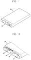
- FIG. 1 is a perspective view showing one example of a related art battery
- FIG. 2 is a perspective view showing the related art battery having no cover member.
- the battery includes a hexahedron-shaped cell 100 filled with electrolyte, etc. and a protection circuit assembly 200 connected to one side of the cell 100.
- the protection circuit assembly 200 stabilizes a current when the battery is charged or discharged.
- the battery also includes a protection cover 300 for covering the protection circuit assembly 200.
- the cell 100 is formed of an aluminum material and is hermetically sealed. Ports 210 of the protection circuit assembly 200 are respectively connected to corresponding ports of the cell 100.
- the protection cover 300 is also formed of a nylon-based resin.
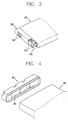
- the protection circuit assembly 200 and the protection cover 300 are coupled to the cell 100 as follows. As shown in FIG. 3, the protection circuit assembly 200 is attached to one side surface of the cell 100 using a spot welding or a laser welding method. Further, the protection cover 300 is formed over the protection circuit assembly 200 using a nylon-based molded resin.
- the protection cover 300 is attached to the aluminum cell 100 using a molded resin, the cell 100 and the protection cover 300 become easily separated from each other when the battery is dropped or when an external force is applied to the battery. Therefore, a gap between the cell 100 and the protection cover 300 is generated.
- FIG. 4 Another example of coupling the protection circuit assembly 200 and the cover 300 to the cell 100 is shown in FIG. 4. As shown in FIG. 4, a nylon-based resin is insert-molded to form the protection cover 300 so the protection circuit assembly 200 can be positioned therein. The protection cover 300 is then attached to one side surface of the cell 100 using a bonding process.
- the related art battery has the following problems. First, it is difficult to bond the protection cover 300 having the protection circuit assembly 200 therein to the cell 100. Also, because the protection cover 300 formed of a nylon-based resin is hardened by a bonding material, it is easily damaged when the battery is dropped or an external impact is applied thereto.
- one object of the present invention is to address the above-noted and other problems.
- Another object of the present invention is to facilitate an assembly of a cell and other components of the battery and to firmly maintain a coupled state therebetween.
- the battery for a mobile communication terminal.
- the battery includes a battery cell, a protection circuit assembly connected to the battery cell and configured to stabilize a current when the battery cell is charged or discharged, a protection cover configured to cover the protection circuit assembly, and a coupling unit configured to couple the protection cover to the battery cell.
- a method of manufacturing a battery for a mobile communication terminal which includes forming a battery cell having a power source for providing power to the mobile terminal, forming a protection circuit assembly for stabilizing the power source of the battery cell when the battery cell is charged or discharged, forming a protection cover for covering the protection circuit assembly, and forming a coupling unit for coupling the protection cover to the battery cell.
- FIGS. 5 and 6 are respectively a perspective view and a disassembled perspective view showing a battery for a mobile communication terminal according to a first embodiment of the present invention.
- the battery includes a cell 400, a protection circuit assembly 500 connected to the cell 400 for stabilizing a current when the battery is charged and discharged, a protection cover 600 covering the protection circuit assembly 500, and a coupling unit 700 for coupling the protection cover 600 to the cell 400.
- the cell 400 preferably has a hexahedron shape, is formed of aluminum, and contains an electrolyte, etc. Ports 410 are also provided at one side of the cell 400.
- the protection circuit assembly 500 and the protection cover 600 are integrally formed using an insertion-molding method.
- the protection cover 600 is formed of a nylon-based resin, and the protection circuit assembly 500 includes ports 510 to be connected to the ports 410 of the cell 400.
- the coupling unit 700 shown in FIG. 5 includes a plurality of hooks 420 protruding from one side of the cell 400, and fixing holes 610 formed on a corresponding position of the protection cover 600 so as to lock and fix in the fixing holes 610. Also shown is a bracket 440 protruding from one side of a body 430 of the cell 400.
- the hooks 420 are preferably formed on the bracket 440 with a certain gap existing between the hooks 420.
- the bracket 440 is also preferably formed as a closed curved line for covering the ports 410 of the cell 400 at a side where the ports 410 are located. As shown in FIG. 6, the hooks 420 are formed at an outer side surface of the bracket 440.
- an extended portion 630 having a length corresponding to a length of the bracket 440 is formed at one side of a body 620 of the protection cover 600.
- the fixing holes 610 are penetratingly-formed at the extended portion 630 and are located at positions to be engaged with the fixing hooks 420. Further, when the protection cover 600 is coupled to the cell 400, the bracket 440 is inserted into the extended portion 630 so the extended portion 630 covers the bracket 440, and the hooks 420 are respectively fitted into the fixing holes 610.
- connection port unit 800 for connecting the ports 510 of the protection circuit assembly 500 to the ports 410 of the cell 400 is provided between the protection circuit assembly 500 and the cell 400.
- the connection port unit 800 is a bent conductive elastic member respectively attached to the ports 410 of the cell 400. That is, one side of the conductive elastic member is respectively attached to the ports 410 of the cell 400.
- the conductive elastic member may also be respectively attached to the ports 510 of the protection circuit assembly 500.
- connection port unit 800 may include a conductive compression member 810 respectively attached to the ports 410 of the cell 400, and a conductive fit member 820 respectively attached to the ports 510 of the protection circuit assembly 500 thus to be fitted into the conductive compression member 810.
- the member 810 may also be formed on the ports 510 and the member 820 formed on the ports 410.
- the battery includes a plurality of hooks 640 protrudingly-formed at an inner side surface of the extended portion 630 of the protection cover 600, and a plurality of fixing holes 450 penetratingly-formed at the bracket 440 of the cell 400 to engage the hooks 640.
- the protection cover 600 and the cell 400 are coupled to each other when the hooks 640 are fitted into the stopping holes 450 of the bracket 440. Note, this structure is substantially opposite to the structure shown in FIGs. 6 and 7.
- the battery includes the cell 400, the protection circuit assembly 500, the protection cover 600, and the coupling unit 700 for coupling the protection cover 600 to the cell 400.
- the coupling unit 700 shown in FIG. 11 includes through holes 650 formed on the protection cover 600, screw holes 460 formed at one side of the cell 400, and coupling screws 710 respectively inserted into the through holes 650 to be coupled to the screw holes 460.
- the protection circuit assembly 500 and the protection cover 600 are integrally formed using an insertion-molding method
- the protection cover 600 is formed of a nylon-based resin
- the protection circuit assembly 500 includes ports 510 connected to the ports 410 of the cell 400.
- the bracket 440 protrudes from one side of the body 430 of the cell 400.
- the plural screw holes 460 are also preferably formed on the bracket 440 with a certain gap therebetween.
- the bracket 440 is also preferably formed as a closed curved line for covering the ports 410 at a side where the ports 410 are formed.
- the extended portion 630 having the length corresponding to a length of the bracket 440 is formed at one side of a body 620 of the protection cover 600, and the through holes 650 are penetratingly-formed at the extended portion 630 with a certain gap therebetween.
- the bracket 440 is inserted into the extended portion 630 so that the extended portion 630 covers the bracket 440.
- the through holes 650 of the protection cover 600 are coupled to the screw holes 460 of the cell 400.
- the coupling screws 710 are respectively coupled to the through holes 650 and the screw holes 460.
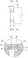
- the connection port unit 800 shown in FIGs. 8 and 9 are provided between the protection circuit assembly 500 and the cell 400.
- an extension portion 660 is formed at one side of the body 620 of the protection cover 600, and a plurality of screw holes 670 are formed at the extension portion 660 with a certain gap therebetween. Further, a bracket 470 having a certain length and thickness corresponding to a length and thickness of the extension portion 660 is formed at one side of the body 430 of the cell 400.
- Through holes 480 having a number corresponding to the number of the screw holes 670 are formed on the bracket 470.
- the extension portion 660 is coupled to the bracket 470, the extension portion 660 is inserted into the bracket 470 of the cell 400.
- the through holes 480 are made to correspond to the screw holes 670, the coupling screws 710 are respectively coupled to the through holes 480 and the screw holes 670. Note, this structure is substantially opposite to the structure shown in FIGs. 12 and 13.
- the protection circuit assembly 500 and the protection cover 600 can be separated from each other or can be integrally formed using an insertion-molding method. Further, the protection cover 600 has a shape for covering the protection circuit assembly 500.
- the protection circuit assembly 500 can be attached to the cell 400 by welding, etc.
- the protection cover 600 is coupled to the cell 400 so as to cover the protection circuit assembly 500.
- the protection circuit assembly 500 is coupled to the cell 400 as the ports 510 thereof are coupled to the ports 410 of the cell 400.
- the protection cover 600 and the cell 400 are coupled to each other as discussed above.
- the battery according to the present invention is detachably mounted at a body of the mobile communication terminal. Electric energy generated from the cell 400 of the battery is stably supplied to the terminal body through the protection circuit assembly 500. When the battery has been discharged, the battery is detached from the terminal body and then is charged. The charged battery is then mounted on the terminal body thus to be re-used.
- the cell 400 and the protection cover 600 are coupled to each other via the hooks 420 and 640 engaging the stopping holes 450 and 610, thereby facilitating an assembly operation.
- the coupled state between the cell 400 and the protection cover 600 is firmly maintained.
- the cell 400 and the protection cover 600 are coupled to each other via the coupling screws 710, thereby facilitating an assembly operation.
- the coupled state between the cell 400 and the protection cover 600 is firmly maintained.
- the battery for a mobile communication terminal As aforementioned, in the battery for a mobile communication terminal according to the present invention, an assembly of the cell and the protection cover constituting the battery is facilitated, which enhance an assembly productivity. Furthermore, because the coupled state of the battery is firmly maintained, the battery is prevented from being damaged when the battery is dropped or an external impact is applied to the battery. Accordingly, the reliability of the battery for the mobile communication terminal is improved.
Landscapes
- Chemical & Material Sciences (AREA)
- Chemical Kinetics & Catalysis (AREA)
- Electrochemistry (AREA)
- General Chemical & Material Sciences (AREA)
- Engineering & Computer Science (AREA)
- Manufacturing & Machinery (AREA)
- Microelectronics & Electronic Packaging (AREA)
- Computer Networks & Wireless Communication (AREA)
- Signal Processing (AREA)
- Battery Mounting, Suspending (AREA)
- Connection Of Batteries Or Terminals (AREA)
- Charge And Discharge Circuits For Batteries Or The Like (AREA)
- Secondary Cells (AREA)
Applications Claiming Priority (1)
| Application Number | Priority Date | Filing Date | Title |
|---|---|---|---|
| KR1020040091613A KR20060042819A (ko) | 2004-11-10 | 2004-11-10 | 배터리의 보호회로 매입형 수지물 체결장치 |
Publications (2)
| Publication Number | Publication Date |
|---|---|
| EP1657776A2 true EP1657776A2 (fr) | 2006-05-17 |
| EP1657776A3 EP1657776A3 (fr) | 2007-05-23 |
Family
ID=35892229
Family Applications (1)
| Application Number | Title | Priority Date | Filing Date |
|---|---|---|---|
| EP05024459A Withdrawn EP1657776A3 (fr) | 2004-11-10 | 2005-11-09 | Batteire pour un terminal de communication mobile |
Country Status (8)
| Country | Link |
|---|---|
| US (1) | US20060099492A1 (fr) |
| EP (1) | EP1657776A3 (fr) |
| JP (1) | JP2006140149A (fr) |
| KR (1) | KR20060042819A (fr) |
| CN (1) | CN100454609C (fr) |
| BR (1) | BRPI0505059A (fr) |
| MX (1) | MXPA05012095A (fr) |
| RU (1) | RU2340984C2 (fr) |
Cited By (4)
| Publication number | Priority date | Publication date | Assignee | Title |
|---|---|---|---|---|
| EP1919022A1 (fr) * | 2006-10-30 | 2008-05-07 | Samsung SDI Co., Ltd. | Batterie secondaire |
| EP2071648A1 (fr) * | 2007-12-14 | 2009-06-17 | Samsung SDI Co., Ltd. | Bloc-batterie |
| EP2190045A1 (fr) | 2008-11-19 | 2010-05-26 | Samsung SDI Co., Ltd. | Bloc-batterie |
| US8632900B2 (en) | 2008-09-22 | 2014-01-21 | Samsung Sdi Co., Ltd. | Secondary battery |
Families Citing this family (31)
| Publication number | Priority date | Publication date | Assignee | Title |
|---|---|---|---|---|
| KR101308272B1 (ko) * | 2006-08-24 | 2013-09-13 | 삼성에스디아이 주식회사 | 리덕션 캐비티가 형성된 이차전지 |
| KR100821857B1 (ko) | 2006-10-23 | 2008-04-15 | 주식회사 엘지화학 | 이차전지 팩 |
| CN101174681B (zh) | 2006-10-30 | 2010-05-12 | 比亚迪股份有限公司 | 极片复合体、电芯和锂离子电池 |
| KR100865392B1 (ko) * | 2006-11-20 | 2008-10-24 | 삼성에스디아이 주식회사 | 배터리 팩 및 이의 제조 방법 |
| KR100934459B1 (ko) | 2006-11-27 | 2009-12-30 | 주식회사 엘지화학 | 생산성과 구조적 안정성이 우수한 전지팩 |
| KR100833745B1 (ko) * | 2007-01-17 | 2008-05-29 | 삼성에스디아이 주식회사 | 이차 전지 |
| KR100875430B1 (ko) * | 2007-01-19 | 2008-12-22 | 삼성에스디아이 주식회사 | 이차 전지용 케이스 및 이를 포함하는 배터리 팩 |
| KR100954589B1 (ko) * | 2007-02-07 | 2010-04-26 | 삼성에스디아이 주식회사 | 보호회로 조립체 및 이를 구비한 배터리 팩 |
| KR100922468B1 (ko) * | 2007-09-21 | 2009-10-21 | 삼성에스디아이 주식회사 | 배터리 팩 |
| JP5306746B2 (ja) * | 2007-09-26 | 2013-10-02 | 日立マクセル株式会社 | 電池パック |
| KR100928120B1 (ko) * | 2007-11-07 | 2009-11-24 | 삼성에스디아이 주식회사 | 이차 전지 |
| US9142810B2 (en) * | 2007-11-07 | 2015-09-22 | Samsung Sdi Co., Ltd. | Rechargeable battery |
| KR100947981B1 (ko) * | 2007-11-12 | 2010-03-18 | 삼성에스디아이 주식회사 | 전지 팩 |
| CN101453002A (zh) | 2007-11-29 | 2009-06-10 | 比亚迪股份有限公司 | 一种电池及其制备方法 |
| CN201146200Y (zh) | 2007-12-18 | 2008-11-05 | 比亚迪股份有限公司 | 一种电池组用壳体及包括该壳体的电池组 |
| JP5132783B2 (ja) * | 2007-12-25 | 2013-01-30 | ビーワイディー カンパニー リミテッド | 加熱端子を有するバッテリシステム |
| US8092936B2 (en) | 2007-12-25 | 2012-01-10 | Byd Co. Ltd. | Electrochemical cell having a coiled core |
| US20090159354A1 (en) | 2007-12-25 | 2009-06-25 | Wenfeng Jiang | Battery system having interconnected battery packs each having multiple electrochemical storage cells |
| US8420254B2 (en) | 2007-12-25 | 2013-04-16 | Byd Co. Ltd. | End cover assembly for an electrochemical cell |
| US8276695B2 (en) | 2007-12-25 | 2012-10-02 | Byd Co. Ltd. | Battery electrode sheet |
| KR101552872B1 (ko) * | 2008-08-08 | 2015-09-18 | 가부시키가이샤 지에스 유아사 | 납 축전지 |
| KR101030906B1 (ko) | 2009-06-18 | 2011-04-22 | 삼성에스디아이 주식회사 | 이차 전지 |
| RU2440836C2 (ru) * | 2010-02-18 | 2012-01-27 | Общество с ограниченной ответственностью "Электроскейт" | Электроскейт |
| JP4793497B2 (ja) * | 2010-03-12 | 2011-10-12 | ソニー株式会社 | 電池パック |
| USD716304S1 (en) * | 2012-02-09 | 2014-10-28 | Hid Global Gmbh | RFID reader |
| KR20140004391A (ko) * | 2012-07-02 | 2014-01-13 | 삼성에스디아이 주식회사 | 배터리 팩 및 케이스 |
| CN103259045B (zh) * | 2013-04-28 | 2016-04-13 | 深圳市力莱电源科技有限公司 | 一种聚合物电池及其封装方法 |
| USD799425S1 (en) * | 2014-01-30 | 2017-10-10 | Nikon Corporation | Battery |
| USD754131S1 (en) * | 2014-09-01 | 2016-04-19 | Samsung Electronics Co., Ltd. | Portable solid state disk |
| USD792409S1 (en) * | 2015-11-11 | 2017-07-18 | Samsung Electronics Co., Ltd. | External solid state drive |
| USD820202S1 (en) * | 2016-07-26 | 2018-06-12 | Robert Bosch Gmbh | Housing for a battery |
Citations (1)
| Publication number | Priority date | Publication date | Assignee | Title |
|---|---|---|---|---|
| EP1093178A1 (fr) * | 1999-03-30 | 2001-04-18 | Matsushita Electric Industrial Co., Ltd. | Batterie rechargeable avec circuit de protection |
Family Cites Families (9)
| Publication number | Priority date | Publication date | Assignee | Title |
|---|---|---|---|---|
| FR2662473B1 (fr) * | 1990-05-23 | 1992-09-11 | Framatome Sa | Dispositif de positionnement simultane de plusieurs elements de liaison filetees. |
| US5298347A (en) * | 1992-09-14 | 1994-03-29 | Motorola, Inc. | Battery pack |
| TW432736B (en) * | 1999-02-23 | 2001-05-01 | Sanyo Electric Co | Pack battery |
| CN100456528C (zh) * | 2000-10-20 | 2009-01-28 | 松下电器产业株式会社 | 产品的保护体形成方法及其装置 |
| US6803144B2 (en) * | 2001-11-01 | 2004-10-12 | Nokia Corporation | Battery pack for electronic device |
| JP2003143053A (ja) * | 2001-11-05 | 2003-05-16 | Citizen Watch Co Ltd | 情報通信システム |
| JP3825738B2 (ja) * | 2002-10-31 | 2006-09-27 | 三洋電機株式会社 | パック電池とその製造方法 |
| CN2631052Y (zh) * | 2003-06-13 | 2004-08-04 | 比亚迪股份有限公司 | 锂离子电池 |
| KR100645256B1 (ko) * | 2004-01-28 | 2006-11-14 | 주식회사 엘지화학 | 조립식 구조의 이차전지 |
-
2004
- 2004-11-10 KR KR1020040091613A patent/KR20060042819A/ko not_active Ceased
-
2005
- 2005-11-02 JP JP2005319928A patent/JP2006140149A/ja active Pending
- 2005-11-07 RU RU2005134250/09A patent/RU2340984C2/ru not_active IP Right Cessation
- 2005-11-09 US US11/269,815 patent/US20060099492A1/en not_active Abandoned
- 2005-11-09 MX MXPA05012095A patent/MXPA05012095A/es active IP Right Grant
- 2005-11-09 EP EP05024459A patent/EP1657776A3/fr not_active Withdrawn
- 2005-11-09 BR BRPI0505059-6A patent/BRPI0505059A/pt not_active IP Right Cessation
- 2005-11-10 CN CNB2005101250077A patent/CN100454609C/zh not_active Expired - Fee Related
Patent Citations (1)
| Publication number | Priority date | Publication date | Assignee | Title |
|---|---|---|---|---|
| EP1093178A1 (fr) * | 1999-03-30 | 2001-04-18 | Matsushita Electric Industrial Co., Ltd. | Batterie rechargeable avec circuit de protection |
Cited By (6)
| Publication number | Priority date | Publication date | Assignee | Title |
|---|---|---|---|---|
| EP1919022A1 (fr) * | 2006-10-30 | 2008-05-07 | Samsung SDI Co., Ltd. | Batterie secondaire |
| US8637172B2 (en) | 2006-10-30 | 2014-01-28 | Samsung Sdi Co., Ltd. | Secondary battery |
| EP2071648A1 (fr) * | 2007-12-14 | 2009-06-17 | Samsung SDI Co., Ltd. | Bloc-batterie |
| US8623531B2 (en) | 2007-12-14 | 2014-01-07 | Samsung Sdi Co. Ltd. | Battery pack |
| US8632900B2 (en) | 2008-09-22 | 2014-01-21 | Samsung Sdi Co., Ltd. | Secondary battery |
| EP2190045A1 (fr) | 2008-11-19 | 2010-05-26 | Samsung SDI Co., Ltd. | Bloc-batterie |
Also Published As
| Publication number | Publication date |
|---|---|
| BRPI0505059A (pt) | 2006-07-04 |
| US20060099492A1 (en) | 2006-05-11 |
| RU2340984C2 (ru) | 2008-12-10 |
| KR20060042819A (ko) | 2006-05-15 |
| EP1657776A3 (fr) | 2007-05-23 |
| JP2006140149A (ja) | 2006-06-01 |
| RU2005134250A (ru) | 2007-05-27 |
| MXPA05012095A (es) | 2006-05-31 |
| CN100454609C (zh) | 2009-01-21 |
| CN1773747A (zh) | 2006-05-17 |
Similar Documents
| Publication | Publication Date | Title |
|---|---|---|
| EP1657776A2 (fr) | Batteire pour un terminal de communication mobile | |
| JP6441589B2 (ja) | バッテリーモジュール | |
| US9793704B2 (en) | Secondary battery pack | |
| EP2731175B1 (fr) | Bloc-batterie secondaire | |
| TWI485912B (zh) | 安裝至電池單元的頂蓋總成、以及包含該頂蓋總成的二次電池組 | |
| EP2731172B1 (fr) | Bloc-pile secondaire | |
| WO2019153459A1 (fr) | Module de batterie | |
| JP7788472B2 (ja) | 電池及び電子製品 | |
| KR101222397B1 (ko) | 배터리 팩 | |
| JP2011527488A (ja) | 電極タブとカバープレートとの接続構造 | |
| JP4499648B2 (ja) | リチウムイオン二次電池 | |
| US8673482B2 (en) | Secondary battery including an extension wall | |
| KR20150059530A (ko) | 이차 전지 | |
| JP2010092853A (ja) | 二次電池 | |
| JP2006164531A (ja) | 電池パック | |
| US7294430B2 (en) | Battery having a wound electrode element | |
| JP2005183242A (ja) | 薄型バッテリーパック | |
| JP2005183157A (ja) | 薄型バッテリーパック | |
| JP4810180B2 (ja) | リチウムイオン電池パック | |
| JP4367744B2 (ja) | 薄型電池 | |
| JP2009252373A (ja) | 電池パック | |
| CN218385668U (zh) | 复合极柱、顶盖组件和电池 | |
| CN223451019U (zh) | 电池壳体及电池 | |
| CN218101611U (zh) | 电池和电子设备 | |
| CN218005043U (zh) | 一种扣式电池 |
Legal Events
| Date | Code | Title | Description |
|---|---|---|---|
| PUAI | Public reference made under article 153(3) epc to a published international application that has entered the european phase |
Free format text: ORIGINAL CODE: 0009012 |
|
| AK | Designated contracting states |
Kind code of ref document: A2 Designated state(s): AT BE BG CH CY CZ DE DK EE ES FI FR GB GR HU IE IS IT LI LT LU LV MC NL PL PT RO SE SI SK TR |
|
| AX | Request for extension of the european patent |
Extension state: AL BA HR MK YU |
|
| PUAL | Search report despatched |
Free format text: ORIGINAL CODE: 0009013 |
|
| AK | Designated contracting states |
Kind code of ref document: A3 Designated state(s): AT BE BG CH CY CZ DE DK EE ES FI FR GB GR HU IE IS IT LI LT LU LV MC NL PL PT RO SE SI SK TR |
|
| AX | Request for extension of the european patent |
Extension state: AL BA HR MK YU |
|
| 17P | Request for examination filed |
Effective date: 20071116 |
|
| 17Q | First examination report despatched |
Effective date: 20071227 |
|
| AKX | Designation fees paid |
Designated state(s): DE FI FR GB IT SE |
|
| STAA | Information on the status of an ep patent application or granted ep patent |
Free format text: STATUS: THE APPLICATION IS DEEMED TO BE WITHDRAWN |
|
| 18D | Application deemed to be withdrawn |
Effective date: 20150217 |