EP1657780A1 - Dispositif sans fil - Google Patents
Dispositif sans fil Download PDFInfo
- Publication number
- EP1657780A1 EP1657780A1 EP05109885A EP05109885A EP1657780A1 EP 1657780 A1 EP1657780 A1 EP 1657780A1 EP 05109885 A EP05109885 A EP 05109885A EP 05109885 A EP05109885 A EP 05109885A EP 1657780 A1 EP1657780 A1 EP 1657780A1
- Authority
- EP
- European Patent Office
- Prior art keywords
- antenna
- circuit board
- axis
- radiating
- mode
- Prior art date
- Legal status (The legal status is an assumption and is not a legal conclusion. Google has not performed a legal analysis and makes no representation as to the accuracy of the status listed.)
- Withdrawn
Links
Images


Classifications
-
- H—ELECTRICITY
- H01—ELECTRIC ELEMENTS
- H01Q—ANTENNAS, i.e. RADIO AERIALS
- H01Q1/00—Details of, or arrangements associated with, antennas
- H01Q1/36—Structural form of radiating elements, e.g. cone, spiral, umbrella; Particular materials used therewith
-
- H—ELECTRICITY
- H01—ELECTRIC ELEMENTS
- H01Q—ANTENNAS, i.e. RADIO AERIALS
- H01Q1/00—Details of, or arrangements associated with, antennas
- H01Q1/12—Supports; Mounting means
- H01Q1/22—Supports; Mounting means by structural association with other equipment or articles
- H01Q1/24—Supports; Mounting means by structural association with other equipment or articles with receiving set
- H01Q1/241—Supports; Mounting means by structural association with other equipment or articles with receiving set used in mobile communications, e.g. GSM
- H01Q1/242—Supports; Mounting means by structural association with other equipment or articles with receiving set used in mobile communications, e.g. GSM specially adapted for hand-held use
- H01Q1/243—Supports; Mounting means by structural association with other equipment or articles with receiving set used in mobile communications, e.g. GSM specially adapted for hand-held use with built-in antennas
-
- H—ELECTRICITY
- H01—ELECTRIC ELEMENTS
- H01Q—ANTENNAS, i.e. RADIO AERIALS
- H01Q1/00—Details of, or arrangements associated with, antennas
- H01Q1/36—Structural form of radiating elements, e.g. cone, spiral, umbrella; Particular materials used therewith
- H01Q1/362—Structural form of radiating elements, e.g. cone, spiral, umbrella; Particular materials used therewith for broadside radiating helical antennas
-
- H—ELECTRICITY
- H01—ELECTRIC ELEMENTS
- H01Q—ANTENNAS, i.e. RADIO AERIALS
- H01Q1/00—Details of, or arrangements associated with, antennas
- H01Q1/36—Structural form of radiating elements, e.g. cone, spiral, umbrella; Particular materials used therewith
- H01Q1/38—Structural form of radiating elements, e.g. cone, spiral, umbrella; Particular materials used therewith formed by a conductive layer on an insulating support
-
- H—ELECTRICITY
- H01—ELECTRIC ELEMENTS
- H01Q—ANTENNAS, i.e. RADIO AERIALS
- H01Q11/00—Electrically-long antennas having dimensions more than twice the shortest operating wavelength and consisting of conductive active radiating elements
- H01Q11/02—Non-resonant antennas, e.g. travelling-wave antenna
- H01Q11/08—Helical antennas
-
- H—ELECTRICITY
- H05—ELECTRIC TECHNIQUES NOT OTHERWISE PROVIDED FOR
- H05K—PRINTED CIRCUITS; CASINGS OR CONSTRUCTIONAL DETAILS OF ELECTRIC APPARATUS; MANUFACTURE OF ASSEMBLAGES OF ELECTRICAL COMPONENTS
- H05K1/00—Printed circuits
- H05K1/02—Details
- H05K1/0213—Electrical arrangements not otherwise provided for
- H05K1/0237—High frequency adaptations
- H05K1/024—Dielectric details, e.g. changing the dielectric material around a transmission line
-
- H—ELECTRICITY
- H05—ELECTRIC TECHNIQUES NOT OTHERWISE PROVIDED FOR
- H05K—PRINTED CIRCUITS; CASINGS OR CONSTRUCTIONAL DETAILS OF ELECTRIC APPARATUS; MANUFACTURE OF ASSEMBLAGES OF ELECTRICAL COMPONENTS
- H05K1/00—Printed circuits
- H05K1/16—Printed circuits incorporating printed electric components, e.g. printed resistors, capacitors or inductors
-
- H—ELECTRICITY
- H05—ELECTRIC TECHNIQUES NOT OTHERWISE PROVIDED FOR
- H05K—PRINTED CIRCUITS; CASINGS OR CONSTRUCTIONAL DETAILS OF ELECTRIC APPARATUS; MANUFACTURE OF ASSEMBLAGES OF ELECTRICAL COMPONENTS
- H05K2201/00—Indexing scheme relating to printed circuits covered by H05K1/00
- H05K2201/09—Shape and layout
- H05K2201/09009—Substrate related
- H05K2201/09063—Holes or slots in insulating substrate not used for electrical connections
-
- H—ELECTRICITY
- H05—ELECTRIC TECHNIQUES NOT OTHERWISE PROVIDED FOR
- H05K—PRINTED CIRCUITS; CASINGS OR CONSTRUCTIONAL DETAILS OF ELECTRIC APPARATUS; MANUFACTURE OF ASSEMBLAGES OF ELECTRICAL COMPONENTS
- H05K2203/00—Indexing scheme relating to apparatus or processes for manufacturing printed circuits covered by H05K3/00
- H05K2203/17—Post-manufacturing processes
- H05K2203/171—Tuning, e.g. by trimming of printed components or high frequency circuits
Definitions
- the present invention relates generally to a wireless device having a body radiation mode, and in particular, to a wireless device comprising a right-handed circularly or elliptically polarised antenna.
- the invention relates also to a method of achieving a right-handed circularly or elliptically polarised antenna in a wireless device.
- a CDMA telephony system is based on spread-spectrum technology and is one of the most widely used digital wireless services today.
- the spread-spectrum signal requires sophisticated broadcast power management and soft hand-overs between base stations. This means that the base stations must be precisely timed.
- each transmitter must maintain its frequency to within one part in ten billions. It is advantageous and desirable to have an antenna in a mobile phone so as to allow the mobile phone to receive messages in the CDMA as well as WCDMA system.
- the U.S. Federal Communications Commission has introduced regulations requiring wireless service providers to supply the location of all system users for emergency situations.
- the Wireless Communications and Public Safety Act also known as E-911, makes 911 the universal emergency number for wireless telephones so that the cellular user who has been in an accident can be automatically located.
- E-911 the Wireless Communications and Public Safety Act
- GPS technology enables accurate timing and synchronization between base stations so that cellular calls can be flawlessly passed from one base station to another.
- the GPS satellites transmit two microwave carrier signals: the L1 frequency (1575.42 MHz) which carries the navigation message and the Standard Positioning Services (SPS) code signals; and the L2 frequency (1227.60 MHz) which is used for ionospheric delay measurement carried out by the Precise Positioning Services (PPS) equipped receivers.
- L1 frequency 1575.42 MHz
- SPS Standard Positioning Services
- PPS Precise Positioning Services
- C/A Coarse Acquisition
- PRN Pseudo Random Noise
- each GPS satellite is assigned a different C/A code PRN, so that each GPS satellite can be identified by a unique PRN code; 2) the Precise (P) Code uses a 10.23 MHz PRN code for modulating both the L1 and L2 carrier phases for the military receivers; and 3) the navigation message, which is used to modulate the L1-C/A or P(Y) code signal, is a 50 Hz signal consisting of data bits that describe the GPS satellite orbits, system time, position, clock corrections, and other system parameters.
- GPS provides both the Standard Positioning Service (SPS) and the Precise Positioning Service (PPS).
- SPS Standard Positioning Service
- PPS Precise Positioning Service
- the GPS antenna is required to be right-handed circularly polarized (RHCP) or right-handed elliptically polarized (RHEP) and to provide near hemispherical coverage in order to achieve optimum performance.
- RHCP right-handed circularly polarized
- RHEP right-handed elliptically polarized
- the GPS antenna In a mobile phone, a communicator device or other small hand-held electronic device, it is preferable for the GPS antenna to be small in size and rugged. Preferably, the antenna can be mass-produced without individual tuning in order to reduce cost.
- U.S. Patent Number 5,986,609 discloses an antenna configured to be enclosed within the flip cover of a radiotelephone and to resonate in three frequency bands including a GPS L1 band.
- the disclosed antenna is a half-wave dipole antenna which includes two tapered radiating elements located on opposite sides of a substrate.
- the size of the antenna is not small enough to be implemented within the phone body.
- Chih-Yu Huang et al. discloses a ceramic patch design. Ceramic patches are known to be compact. However, small ceramic patch antennas are extremely narrow-banded and need to be individually tuned.
- Kraus discusses a quadrifilar helix in which each of the four (1/2) ⁇ wires forms a half-turn of a helix on a cylindrical frame.
- the quadrifilar helical antennas as disclosed are unpractically large for mobile phones and small-sized, hand-held devices.
- an aim of the present invention to provide a miniature circularly or elliptically polarized antenna having sufficient gain which can be mounted on or enclosed within a mobile phone or other miniature hand-held electronic device.
- the antenna can be designed to resonate over the GPS frequency bands or other radio frequency bands with improved radiation efficiency over the existing miniature antennas.
- the present invention provides a wireless device, having a body radiation mode, the wireless device comprising: a right-handed circularly or elliptically polarised antenna and a circuit board for mounting the antenna.
- the circuit board has four corners to define a plane having a first axis and a second axis perpendicular to the first axis.
- the radio-frequency antenna comprises a radiator part and a support frame for effecting dielectric loading on the radiator part.
- the radiator part comprises a resonating region for transmitting and receiving signals in the radio-frequency range, a feeding region coupled to the resonating region for impedance matching, and an electrically grounded end located in the proximity of the feeding region.
- the circuit board comprises the radiator part, mounted at one of the corners of the circuit board, to generate a first radiating mode along the first axis and a second radiating mode along the second axis such that a phase shift exists between the first radiating mode and the second radiating mode, the first and second radiating modes forming an antenna radiating mode, wherein the antenna radiating mode is orthogonal to the body radiation mode, and a slit formed between corners of the circuit board to tune the body radiation mode.
- the radiator part as described above is divided into a resonating region and a feeding region only in a loose sense.
- the feeding region also affects the resonating properties of the antenna as it also affects the radiating modes of the antenna.
- two or more antennas can be implemented on different corners of the substrate so that one antenna can be selected by switching means to achieve improved circular or elliptical polarization.
- a further aspect of the present invention provides a method of achieving a right-handed circularly or elliptically polarised antenna in a wireless device having a body radiation mode, said wireless device comprising a circuit board for mounting the antenna.
- the circuit board has four corners to define a plane having a first axis and a second axis perpendicular to the first axis.
- the radio-frequency antenna comprises a radiator part and a support frame for effecting dielectric loading on the radiator part.
- the radiator part comprises a resonating region for transmitting and receiving signals in the radio-frequency range, a feeding region coupled to the resonating region for impedance matching, and an electrically grounded end located in the proximity of the feeding region.
- the method comprises the steps of providing at one of the corners of the circuit board the radiator part to generate a first radiating mode along the first axis and a second radiating mode along the second axis such that a phase shift exists between the first radiating mode and the second radiating mode, the first and second radiating modes forming an antenna radiating mode, wherein the antenna radiating mode is orthogonal to the body radiation mode; and providing a slit formed between corners of the circuit board (106) to tune the body radiation mode.
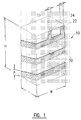
- Figure 1 is an isometric view showing a helical antenna, useable in the preferred embodiment of the present invention.
- Figure 2 is an exploding view showing the preferred location for implementing the radio frequency antenna in a mobile phone.
- Figure 3 is a perspective view showing a mobile phone having a mobile phone antenna and a radio frequency antenna.
- Figures 4a-4c are diagrammatic representations showing different implementations of the radio frequency antenna on a Printed-Circuit Board (PCB).
- Figure 5 is a diagrammatic representation showing a method of tuning the PCB for optimizing the polarization purity of the radio frequency antenna.
- Figure 6 is a diagrammatic representation showing a method of achieving an improved circular or elliptical polarization.
- Figure 7 is an isometric view showing another embodiment of the present invention.
- Figure 8 is a plot showing the bandwidth of a helical antenna in comparison with the bandwidth of a ceramic patch antenna.
- Figures 9a-9c are plots showing the radiation pattern of a mobile phone having a
- the radio frequency or GPS antenna 10 includes an electrically conducting radiating element 20 constructed around a supporting block 30.
- the supporting block 30 is made of a material having a relative permittivity in the range of 2 to 50 so as to effect dielectric loading to the antenna. Dielectric loading is used so that the size of the antenna can be suitably reduced so that the antenna can be used in a mobile phone or other small hand held devices.
- the approximate dimensions of the supporting block 30 are denoted by H, W and T.
- the radiating element 20 has a helical shape spiraling around the supporting block 30.
- the feed of the radiating element 20 is tapped for impedance matching.
- one end of the radiating element 20 is short-circuited to a ground (not shown) by a grounding pin 22, and a feeding pin 24 is connected to the radiating element 20 to provide a feed point at the close proximity of the grounding point.
- the radiating element 20 constitutes the resonating region of the antenna while the grounding pin 22 and the feeding pin 24 constitute the feeding region of the antenna.
- the feeding pin 24 is used as a signal conduit to retrieve signals from the resonating region while the ground pin 22 is used as an impedance matching part for matching the impedance of the resonating region.
- the radiating element 20 which is a helix having two and a half turns to make up a length of approximately 50mm.
- the size of the antenna 10 is sufficiently small to be installed in a mobile phone or other hand-held electronic device.
- the widths A, B, D of the radiating element 20, grounding pin 22 and feeding pin 24, respectively, are approximately equal to 1mm, while the distance between the grounding pin 22 and the feeding pin 24 is approximately 3 to 5mm. It is understood that the dimensions of the various parts of the antenna 30 can be changed according to the shape of the radiating element 20 and the relative permittivity of the supporting block 30.
- reference numeral 100 denotes a mobile phone or a communicator having a front portion 102 including a mobile phone antenna 103, a chassis 104, a printed-circuit board (PCB) 106 and a back cover 110. It is preferred that the GPS antenna 10, according to the present invention, be mounted on the PCB 106.
- PCB printed-circuit board
- the radio frequency antenna When used in an electronic device, such as a mobile phone, which has by itself a certain radiating mode, the radio frequency antenna must be oriented and placed in such a way that the radiating mode in the antenna is orthogonal and in 90 degree phase shift compared to the radiating mode of the device body.
- the radio frequency antenna according to the present invention has the advantage of being able to be implemented differently and at different parts of an electronic device.
- FIGS 4a-4c are diagrammatic representations showing different implementations of the GPS or radio frequency antenna 10 on the PCB 106.
- the GPS antenna 10 is mounted in one of the corners of the PCB 106.
- two radiating modes are generated in the phone body: one along the Y axis and one along the X axis. Because the wave number of one mode is different from the wave number of the other mode, a phase shift exists between the radiation patterns of the two radiation modes. This phase shift is essential in generating the circular polarization.
- the radiation in the Z direction is right-handed circularly or elliptically polarized while the radiation in the -Z direction is left-handed circularly or elliptically polarized.
- the antenna 10 is placed in the upper left corner of the PCB 106 as shown in Figure 4b, the radiation in the Z direction is left-handed circularly or elliptically polarized while the radiation in the -Z direction is right-handed circularly elliptically polarized.
- Figure 7 shows another embodiment of the radiating element of the GPS or radio frequency antenna.
- the radiating element 40 of the GPS antenna 12 is a meander line having a grounding pin 42 and a feeding pin 44.
- the meander line can be implemented on one or more surfaces of the supporting block 30.
- the miniature antenna of the present invention has a broader bandwidth than a compact ceramic patch antenna operating at the GPS frequencies.
- the dash line represents the response of a helical GPS antenna according to the present invention, while the solid line represents the response of a typical ceramic patch antenna.
- the helix GPS antenna has a bandwidth of approximately 80MHz, as shown at the -6dB points on the plot.
- Figures 9a-9c are plots showing the right-handed circular or elliptical polarization radiation patterns of the helix antenna in different planes of the phone body.
- the GPS antenna 10 is implemented on the PCB 106 as shown in Figure 4a or Figure 4b
- the radiating pattern of a mobile phone having a helical GPS antenna at the GPS frequencies in a plane parallel to the WT plane of the antenna is shown in Figure 9a.
- the radiating pattern in a plane parallel to the HT plane of the antenna is shown in Figure 9b while the radiation pattern in the HW plane is shown in Figure 9c.
- the present invention has been disclosed according to the preferred embodiment of a normal mode monofilar helical antenna with dielectric loading and tapped feed.
- the shape of the radiating element and the shape of the supporting block can be changed without departing from the scope of the present invention.
- the radiating element can be shaped as a meander line as shown in Figure 7 or a combination of a meander line and a helix.
- the ⁇ /4 wire (the radiating element) can also be twisted in many different ways.
- the radiating element can be a (3/4) ⁇ or a (5/4) ⁇ , and so forth.
- the major radiation in a mobile phone is coming from the phone body. Depending on the location of the GPS antenna on the phone body, different radiating modes are generated to the phone body. Thus, the radiation properties of the antenna and the phone depend considerably on the location of the GPS antenna.
- the antenna according to the present invention, is applicable to all radio frequencies and it can also be used in a wireless device, such as a mobile phone, to receive messages or signals in the CDMA and WCDMA systems.
Landscapes
- Engineering & Computer Science (AREA)
- Computer Networks & Wireless Communication (AREA)
- Microelectronics & Electronic Packaging (AREA)
- Support Of Aerials (AREA)
- Waveguide Aerials (AREA)
- Variable-Direction Aerials And Aerial Arrays (AREA)
Applications Claiming Priority (2)
| Application Number | Priority Date | Filing Date | Title |
|---|---|---|---|
| US09/553,265 US6653978B2 (en) | 2000-04-20 | 2000-04-20 | Miniaturized radio frequency antenna |
| EP01302830A EP1152482A3 (fr) | 2000-04-20 | 2001-03-27 | Antenne radioélectrique miniaturisée |
Related Parent Applications (1)
| Application Number | Title | Priority Date | Filing Date |
|---|---|---|---|
| EP01302830A Division EP1152482A3 (fr) | 2000-04-20 | 2001-03-27 | Antenne radioélectrique miniaturisée |
Publications (1)
| Publication Number | Publication Date |
|---|---|
| EP1657780A1 true EP1657780A1 (fr) | 2006-05-17 |
Family
ID=24208777
Family Applications (2)
| Application Number | Title | Priority Date | Filing Date |
|---|---|---|---|
| EP01302830A Ceased EP1152482A3 (fr) | 2000-04-20 | 2001-03-27 | Antenne radioélectrique miniaturisée |
| EP05109885A Withdrawn EP1657780A1 (fr) | 2000-04-20 | 2001-03-27 | Dispositif sans fil |
Family Applications Before (1)
| Application Number | Title | Priority Date | Filing Date |
|---|---|---|---|
| EP01302830A Ceased EP1152482A3 (fr) | 2000-04-20 | 2001-03-27 | Antenne radioélectrique miniaturisée |
Country Status (2)
| Country | Link |
|---|---|
| US (1) | US6653978B2 (fr) |
| EP (2) | EP1152482A3 (fr) |
Cited By (3)
| Publication number | Priority date | Publication date | Assignee | Title |
|---|---|---|---|---|
| WO2008092511A1 (fr) * | 2007-02-02 | 2008-08-07 | Sony Ericsson Mobile Communications Ab | Petit dispositif portable de communication |
| CN101601166B (zh) * | 2007-02-02 | 2013-01-02 | 索尼爱立信移动通讯股份有限公司 | 小型便携式通信设备 |
| CN108039582A (zh) * | 2017-12-01 | 2018-05-15 | 广东欧珀移动通信有限公司 | 中框组件、天线组件及电子设备 |
Families Citing this family (12)
| Publication number | Priority date | Publication date | Assignee | Title |
|---|---|---|---|---|
| JP4507445B2 (ja) * | 2001-04-25 | 2010-07-21 | パナソニック株式会社 | 表面実装型アンテナ及びそれを用いた電子機器 |
| DE10209961A1 (de) * | 2002-03-06 | 2003-09-25 | Philips Intellectual Property | Mikrowellenantenne |
| US7027838B2 (en) * | 2002-09-10 | 2006-04-11 | Motorola, Inc. | Duel grounded internal antenna |
| GB2401248B (en) * | 2003-04-30 | 2005-03-30 | Motorola Inc | Antenna for use in radio communications |
| US20060232481A1 (en) * | 2003-08-21 | 2006-10-19 | Koninklijke Philips Electronics N.V. | Wideband antenna module for the high-frequency and microwave range |
| WO2005086281A1 (fr) * | 2004-02-25 | 2005-09-15 | Philips Intellectual Property & Standards Gmbh | Reseau d'antennes |
| US7627296B2 (en) * | 2004-10-18 | 2009-12-01 | Research In Motion Limited | Method of controlling a plurality of internal antennas in a mobile communication device |
| US20080129637A1 (en) * | 2006-11-30 | 2008-06-05 | Yun-Wen Chi | Dual-band loop antenna |
| GB2444750B (en) * | 2006-12-14 | 2010-04-21 | Sarantel Ltd | An antenna arrangement |
| US7800546B2 (en) | 2007-09-06 | 2010-09-21 | Research In Motion Limited | Mobile wireless communications device including multi-loop folded monopole antenna and related methods |
| US8803749B2 (en) * | 2011-03-25 | 2014-08-12 | Kwok Wa Leung | Elliptically or circularly polarized dielectric block antenna |
| GB201122324D0 (en) | 2011-12-23 | 2012-02-01 | Univ Edinburgh | Antenna element & antenna device comprising such elements |
Citations (3)
| Publication number | Priority date | Publication date | Assignee | Title |
|---|---|---|---|---|
| EP0548975A1 (fr) * | 1991-12-26 | 1993-06-30 | Kabushiki Kaisha Toshiba | Appareils de radio et radiotéléphones portables avec des fentes dans ceux-ci |
| JPH1188209A (ja) * | 1997-09-11 | 1999-03-30 | Mitsubishi Electric Corp | 移動通信機 |
| JPH11154815A (ja) * | 1997-09-19 | 1999-06-08 | Toshiba Corp | アンテナ装置 |
Family Cites Families (14)
| Publication number | Priority date | Publication date | Assignee | Title |
|---|---|---|---|---|
| EP0743699B1 (fr) | 1995-05-17 | 2001-09-12 | Murata Manufacturing Co., Ltd. | Système d'antenne montable en surface |
| JPH0993021A (ja) * | 1995-09-25 | 1997-04-04 | Murata Mfg Co Ltd | チップアンテナ |
| US5696517A (en) * | 1995-09-28 | 1997-12-09 | Murata Manufacturing Co., Ltd. | Surface mounting antenna and communication apparatus using the same |
| JP3114605B2 (ja) * | 1996-02-14 | 2000-12-04 | 株式会社村田製作所 | 表面実装型アンテナおよびこれを用いた通信機 |
| JP3055456B2 (ja) * | 1996-02-21 | 2000-06-26 | 株式会社村田製作所 | アンテナ装置 |
| JPH10145125A (ja) * | 1996-09-10 | 1998-05-29 | Murata Mfg Co Ltd | アンテナ装置 |
| JP2996191B2 (ja) * | 1996-12-25 | 1999-12-27 | 株式会社村田製作所 | チップアンテナ |
| DE69834150T2 (de) * | 1997-03-05 | 2007-01-11 | Murata Mfg. Co., Ltd., Nagaokakyo | Mobiles Bildgerät und Antennenvorrichtung dafür |
| JPH10247808A (ja) * | 1997-03-05 | 1998-09-14 | Murata Mfg Co Ltd | チップアンテナ及びその周波数調整方法 |
| US5926139A (en) * | 1997-07-02 | 1999-07-20 | Lucent Technologies Inc. | Planar dual frequency band antenna |
| FR2778500B1 (fr) | 1998-05-05 | 2000-08-04 | Socapex Amphenol | Antenne a plaque |
| FR2778499B1 (fr) * | 1998-05-05 | 2000-08-11 | Socapex Amphenol | Antenne a plaque |
| US5986609A (en) | 1998-06-03 | 1999-11-16 | Ericsson Inc. | Multiple frequency band antenna |
| US6353443B1 (en) * | 1998-07-09 | 2002-03-05 | Telefonaktiebolaget Lm Ericsson (Publ) | Miniature printed spiral antenna for mobile terminals |
-
2000
- 2000-04-20 US US09/553,265 patent/US6653978B2/en not_active Expired - Fee Related
-
2001
- 2001-03-27 EP EP01302830A patent/EP1152482A3/fr not_active Ceased
- 2001-03-27 EP EP05109885A patent/EP1657780A1/fr not_active Withdrawn
Patent Citations (4)
| Publication number | Priority date | Publication date | Assignee | Title |
|---|---|---|---|---|
| EP0548975A1 (fr) * | 1991-12-26 | 1993-06-30 | Kabushiki Kaisha Toshiba | Appareils de radio et radiotéléphones portables avec des fentes dans ceux-ci |
| JPH1188209A (ja) * | 1997-09-11 | 1999-03-30 | Mitsubishi Electric Corp | 移動通信機 |
| JPH11154815A (ja) * | 1997-09-19 | 1999-06-08 | Toshiba Corp | アンテナ装置 |
| US6147652A (en) * | 1997-09-19 | 2000-11-14 | Kabushiki Kaisha Toshiba | Antenna apparatus |
Non-Patent Citations (3)
| Title |
|---|
| MURAKAMI Y ET AL: "RECTANGULAR LOOP ANTENNA FOR CIRCULAR POLARIZATION", ELECTRONICS & COMMUNICATIONS IN JAPAN, PART I - COMMUNICATIONS, WILEY, HOBOKEN, NJ, US, vol. 79, no. 3, 1 March 1996 (1996-03-01), pages 42 - 51, XP000583429, ISSN: 8756-6621 * |
| PATENT ABSTRACTS OF JAPAN vol. 1999, no. 08 30 June 1999 (1999-06-30) * |
| PATENT ABSTRACTS OF JAPAN vol. 1999, no. 11 30 September 1999 (1999-09-30) * |
Cited By (4)
| Publication number | Priority date | Publication date | Assignee | Title |
|---|---|---|---|---|
| WO2008092511A1 (fr) * | 2007-02-02 | 2008-08-07 | Sony Ericsson Mobile Communications Ab | Petit dispositif portable de communication |
| US7612723B2 (en) | 2007-02-02 | 2009-11-03 | Sony Ericsson Mobile Communications Ab | Portable communication device antenna arrangement |
| CN101601166B (zh) * | 2007-02-02 | 2013-01-02 | 索尼爱立信移动通讯股份有限公司 | 小型便携式通信设备 |
| CN108039582A (zh) * | 2017-12-01 | 2018-05-15 | 广东欧珀移动通信有限公司 | 中框组件、天线组件及电子设备 |
Also Published As
| Publication number | Publication date |
|---|---|
| US6653978B2 (en) | 2003-11-25 |
| US20020000935A1 (en) | 2002-01-03 |
| EP1152482A3 (fr) | 2002-12-11 |
| EP1152482A2 (fr) | 2001-11-07 |
Similar Documents
| Publication | Publication Date | Title |
|---|---|---|
| US6653978B2 (en) | Miniaturized radio frequency antenna | |
| RU2225058C2 (ru) | Антенная система и устройство радиосвязи, включающее антенную систему | |
| US6380903B1 (en) | Antenna systems including internal planar inverted-F antennas coupled with retractable antennas and wireless communicators incorporating same | |
| US6417816B2 (en) | Dual band bowtie/meander antenna | |
| KR100612798B1 (ko) | 이동 단말기용 소형 인쇄된 나선형 안테나 | |
| US6326919B1 (en) | Patch antenna | |
| US20060232493A1 (en) | Circular-polarization dipole helical antenna | |
| EP1826868A2 (fr) | Antenne de résonateur diélectrique polarisée circulairement | |
| US6225951B1 (en) | Antenna systems having capacitively coupled internal and retractable antennas and wireless communicators incorporating same | |
| WO2009048480A2 (fr) | Mode transparent de système de brouillage | |
| EP1166390A1 (fr) | Systeme bimodal compact d'antenne integree pour telecommunications cellulaires terrestres et par satellite | |
| EP1332533A2 (fr) | Antennes a fente et dispositifs de communications hertziennes les contenant | |
| US6563466B2 (en) | Multi-frequency band inverted-F antennas with coupled branches and wireless communicators incorporating same | |
| US7158819B1 (en) | Antenna apparatus with inner antenna and grounded outer helix antenna | |
| US6778149B2 (en) | Composite antenna apparatus | |
| GB2351849A (en) | Multi-band helical antenna with varying pitch | |
| US20020123312A1 (en) | Antenna systems including internal planar inverted-F Antenna coupled with external radiating element and wireless communicators incorporating same | |
| JP4565305B2 (ja) | 携帯無線端末装置 | |
| US20070139271A1 (en) | Method for access to a medium by a multi-channel device | |
| EP0876688B1 (fr) | Antenne pour frequences superieures a 200 mhz | |
| Hong et al. | Low profile S-band dual-polarized antenna for SDARS application | |
| US11824266B2 (en) | Encapsulated multi-band monopole antenna | |
| KR100861882B1 (ko) | 다중대역 안테나 | |
| JPH10135734A (ja) | 共用アンテナ装置およびこれを用いた携帯無線機 | |
| WO2001020716A1 (fr) | Systeme d'antenne et procede servant a reduire la taille du fouet dudit systeme d'antenne |
Legal Events
| Date | Code | Title | Description |
|---|---|---|---|
| PUAI | Public reference made under article 153(3) epc to a published international application that has entered the european phase |
Free format text: ORIGINAL CODE: 0009012 |
|
| AC | Divisional application: reference to earlier application |
Ref document number: 1152482 Country of ref document: EP Kind code of ref document: P |
|
| AK | Designated contracting states |
Kind code of ref document: A1 Designated state(s): AT BE BG CH CY CZ DE DK EE ES FI FR GB GR HU IE IS IT LI LT LU LV MC NL PL PT RO SE SI SK TR |
|
| AX | Request for extension of the european patent |
Extension state: AL BA HR MK YU |
|
| 17P | Request for examination filed |
Effective date: 20060629 |
|
| 17Q | First examination report despatched |
Effective date: 20061016 |
|
| AKX | Designation fees paid |
Designated state(s): DE FI FR GB NL |
|
| STAA | Information on the status of an ep patent application or granted ep patent |
Free format text: STATUS: THE APPLICATION IS DEEMED TO BE WITHDRAWN |
|
| 18D | Application deemed to be withdrawn |
Effective date: 20111001 |