EP1657788A1 - Mehrband-Antennenanordnung mit konzentrisch angeordneter Stab- und Mikrostreifen-Patch-Antenne - Google Patents
Mehrband-Antennenanordnung mit konzentrisch angeordneter Stab- und Mikrostreifen-Patch-Antenne Download PDFInfo
- Publication number
- EP1657788A1 EP1657788A1 EP05077530A EP05077530A EP1657788A1 EP 1657788 A1 EP1657788 A1 EP 1657788A1 EP 05077530 A EP05077530 A EP 05077530A EP 05077530 A EP05077530 A EP 05077530A EP 1657788 A1 EP1657788 A1 EP 1657788A1
- Authority
- EP
- European Patent Office
- Prior art keywords
- antenna
- mast
- communication band
- arrangement
- microstrip patch
- Prior art date
- Legal status (The legal status is an assumption and is not a legal conclusion. Google has not performed a legal analysis and makes no representation as to the accuracy of the status listed.)
- Withdrawn
Links
Images


Classifications
-
- H—ELECTRICITY
- H01—ELECTRIC ELEMENTS
- H01Q—ANTENNAS, i.e. RADIO AERIALS
- H01Q21/00—Antenna arrays or systems
- H01Q21/30—Combinations of separate antenna units operating in different wavebands and connected to a common feeder system
-
- H—ELECTRICITY
- H01—ELECTRIC ELEMENTS
- H01Q—ANTENNAS, i.e. RADIO AERIALS
- H01Q21/00—Antenna arrays or systems
- H01Q21/24—Combinations of antenna units polarised in different directions for transmitting or receiving circularly and elliptically polarised waves or waves linearly polarised in any direction
-
- H—ELECTRICITY
- H01—ELECTRIC ELEMENTS
- H01Q—ANTENNAS, i.e. RADIO AERIALS
- H01Q9/00—Electrically-short antennas having dimensions not more than twice the operating wavelength and consisting of conductive active radiating elements
- H01Q9/04—Resonant antennas
- H01Q9/0407—Substantially flat resonant element parallel to ground plane, e.g. patch antenna
-
- H—ELECTRICITY
- H01—ELECTRIC ELEMENTS
- H01Q—ANTENNAS, i.e. RADIO AERIALS
- H01Q9/00—Electrically-short antennas having dimensions not more than twice the operating wavelength and consisting of conductive active radiating elements
- H01Q9/04—Resonant antennas
- H01Q9/30—Resonant antennas with feed to end of elongated active element, e.g. unipole
Definitions
- This disclosure relates generally to antennas. More particularly, the disclosure relates to antennas for use in receiving satellite-broadcast signals.
- vehicle communication systems for receiving or transmitting signals.
- vehicle audio systems provide information and entertainment to many motorists daily. These audio systems typically include an AM/FM radio receiver that receives radio frequency (RF) signals. These RF signals are then processed and rendered as audio output.
- RF radio frequency
- a vehicle communication system may incorporate other functions, including, but not limited to, wireless voice and data communications, global positioning system (GPS) functionality, satellite-based digital audio radio service (SDARS) functionality, keyless entry, and remote vehicle starting.
- GPS global positioning system
- SDARS satellite-based digital audio radio service
- Communication systems typically employ antenna systems including one or more antennas to receive or transmit electromagnetic radiated signals.
- antenna systems typically employ antenna systems including one or more antennas to receive or transmit electromagnetic radiated signals.
- antenna systems have predetermined patterns and frequency characteristics. These predetermined characteristics are selected in view of various factors, including, for example, the ideal antenna design, physical antenna structure limitations, and mobile environment requirements.
- Some antenna modules incorporate multiple antennas for use in different applications, including cellular telephony in the AMPS, PCS, and GSM communication bands, digital audio broadcast (DAB), GPS, and SDARS systems. These antennas can be stacked or placed on the same circuit board, for example, arranged adjacent to one another in a row.
- DAB digital audio broadcast
- GPS GPS
- SDARS Secure Digital
- antenna mast One type of antenna, known as an antenna mast, is commonly used in high frequency communications.
- antenna masts may be used inwireless voice and data communications systems operating at frequencies up to and even in excess of 1 GHz.
- An antenna mast may be implemented, for example, as a flexible fiberglass or TEFLON® rod with a helically-wound conductor for receiving radio signals.
- Small mast antennas such as those used for cellular telephony, distort the radiation pattern for satellite services, e.g., GPS, and SDARS, due to coupling and shadowing.
- satellite services e.g., GPS, and SDARS
- this distortion is normally acceptable.
- larger mast antennas such as those used for AM and FM radio reception, present significantly more distortion in the radiation patterns for satellite services. Accordingly, larger mast antennas cannot be placed adjacent to satellite antennas.
- a concentric antenna arrangement In such an arrangement, a helical antenna for use with satellite services such as GPS and SDARS is arranged concentrically with a mast antenna for reception of terrestrial signals, such as DAB or cellular telephone signals.
- the helical antenna which operates at its axial mode, can be constructed using a thin, flexible substrate or a wire wrapped into a cylindrical shape.
- the cables or wires for the mast antenna are typically routed inside and concentric to the helical antenna. Accordingly, the mast antenna is thicker and more rigid than traditional AM/FM mast antennas.
- One drawback to this type of design is that the helical antenna cannot be bent along its length.
- the mast antenna needs to be tilted for a particular vehicle application, the helical antenna must also be tilted, potentially resulting in an unacceptable radiation pattern for the helical antenna.
- an antenna module incorporates a microstrip patch antenna and a mast antenna in an at least substantially concentric arrangement for communicating signals in multiple communication bands.
- the output signals from the microstrip patch antenna and the mast antenna are output via a single RF cable.
- One embodiment is directed to an antenna arrangement including a mast antenna and a microstrip patch antenna located proximate and at least substantially concentrically with the mast antenna.
- Another embodiment is directed to a communication system including a receiver and an antenna arrangement.
- the antenna arrangement includes a mast antenna and a microstrip patch antenna located proximate and at least substantially concentrically with the mast antenna.
- the antenna module can be used to communicate signals in multiple communication bands, including both satellite and terrestrial communications.
- the antenna module conserves space, while avoiding unacceptable distortion of radiation patterns for satellite services.
- the mast antenna can be implemented using a thinner, more flexible construction than certain conventional solutions. Further, providing the outputs from the antennas via a single RF cable may facilitate collocating tuners for multiple communication services, resulting in considerable size and cost savings by using a single set of RF cables and connectors.
- An antenna module incorporates a microstrip patch antenna and a mast antenna in an at least substantially concentric arrangement for communicating signals in multiple communication bands.
- the output signals from the microstrip patch antenna and the mast antenna are output via a single RF cable.
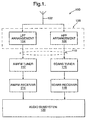
- FIG. 1 illustrates an example communication system 100, such as a vehicle entertainment system.
- an antenna arrangement 102 receives radio frequency (RF) signals.
- the RF signals can be received from satellite and terrestrial transmitters.
- satellite transmitters include, but are not limited to, satellite digital audio radio service (SDARS) transmitters and global positioning system (GPS) satellites.
- SDARS satellite digital audio radio service
- GPS global positioning system
- Terrestrial transmitters can transmit signals in a variety of communication bands, including, but not limited to, an AM communication band, an FM communication band, a digital audio broadcast (DAB) communication band, an advanced mobile phone service (AMPS) cellular telephony communication band, a personal communications services (PCS) cellular telephony communication band, a global system for mobile (GSM) cellular telephony communication band, or an industrial-scientific-medical (ISM) communication band.
- the antenna arrangement 102 is described as receiving RF signals from an SDARS satellite transmitter and an AM or FM terrestrial transmitter. However, it will be appreciated by those of skill in the art that the principles described herein can be applied to implement other multiband configurations involving satellite and terrestrial transmitters.
- the RF signals are conducted from the antenna arrangement 102 to a low pass filter (LPF) arrangement 104 and a high pass filter (HPF) arrangement 106.
- LPF low pass filter
- HPF high pass filter
- the LPF arrangement 104 passes the terrestrial signal, e.g., the AM or FM radio signal.
- the HPF arrangement 106 passes the satellite signal, e.g., the SDARS signal.
- the LPF arrangement 104 and the HPF arrangement 106 may each be associated with respective amplifiers (not shown), and may be implemented on a single circuit board 108.
- the output signals generated by the LPF arrangement 104 and the HPF arrangement 106 may be combined as a single output signal using a crossover network and output via a single RF cable 110. In this way, the number of RF connectors required may be reduced, resulting in size and cost savings.
- the AM or FM radio signal is conducted to an AM/FM tuner 112 and, in turn, to an AM/FM receiver 114.
- the SDARS signal is conducted to an SDARS tuner 116 and, in turn, to an SDARS tuner 118.
- the antenna arrangement 102 is operatively coupled to the AM/FM receiver 114 and the SDARS receiver 118 through the AM/FM tuner 112 and the SDARS tuner 116, respectively. It will be appreciated by those skilled in the art that the antenna arrangement 102 can be operatively coupled to multiple communication devices. Some such communication devices may have both transmitting and receiving capabilities, and may be connected to antennas, such as transmitting antennas, other than the antenna arrangement 102.
- the communication devices may be operatively coupled to the antenna via a high-speed data bus (not shown).
- the communication devices may include, e.g., one or more receivers in combination with one or more transmitters.
- the AM/FM receiver 114 and the SDARS receiver 118 are operatively coupled to an audio subsystem 120, which may include a number of speakers.
- the receiver may be operatively coupled to the audio subsystem 120 through one or more intermediate devices.
- the SDARS receiver 118 may be operatively coupled to the audio subsystem 120 through a decoder (not shown), which decodes the RF signals received by the SDARS receiver 118.
- the decoder may also perform an authentication function to verify that the communication system 100 is authorized to receive programming embodied in the RF signal.
- the decoded signal may contain audio and video components.
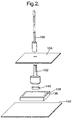
- FIG 2 is an exploded view of an example implementation of the antenna arrangement 102.
- Figure 3 is an assembled view of the implementation of the antenna arrangement 102 shown in the exploded view of Figure 2.
- a mast antenna 130 is configured to receive terrestrial RF signals, for example, in the AM or FM communication band. Alternatively, the mast antenna 130 can be configured to receive and/or transmit terrestrial RF signals in other communication bands, including, but not limited to, the DAB, AMPS, PCS, GSM, and ISM communication bands.
- the mast antenna 130 is mounted on a metal stud 132 that extends through a plastic cover 134. A portion of the metal stud 132 that extends from the plastic cover 134 is threaded to facilitate mounting the mast antenna 130.
- a portion of the metal stud 132 that is located under the plastic cover 134 is convex. This convex shape facilitates insertion of the metal stud 132 into the plastic cover 134 at a variety of angles, thereby allowing the mast antenna 130 to be tilted.
- a microstrip patch antenna is formed by a dielectric layer 136 and a conductive layer 138 formed proximate a top side of the dielectric layer 136.
- the microstrip patch antenna is located proximate and at least substantially concentrically with the mast antenna 130.
- An elastomeric conductive pad 140 electrically connects the conductive layer 138 of the microstrip patch antenna to the metal stud 132 when the plastic cover 134 is attached.
- the elastomeric conductive pad 140 is attached to either the conductive layer 138 of the microstrip patch antenna or the metal stud 132 using an adhesive during manufacturing. Attaching the plastic cover 134 compresses the elastomeric conductive pad 140, establishing the electrical connection between the conductive layer 138 of the microstrip patch antenna and the metal stud 132.
- a patch feed pin (not shown) is connected to a circuit board 142 that contains, for example, the LPF arrangement 104 and the HPF arrangement 106 of Figure 1.
- the signal from the patch feed pin is connected to the input of the AM/FM tuner 112 of Figure 1 through the LPF arrangement 104.
- the signal from the patch feed pin is also connected to the input of the SDARS tuner 116 of Figure 1 through the HPF arrangement 106.
- the insertion loss of the HPF arrangement 106 is very small and does not significantly affect the noise figure of the SDARS system.
- the implementation of the antenna arrangement 102 shown in Figures 2 and 3 may offer certain advantages.
- the elastomeric conductive pad 140 provides mechanical isolation between the antenna mast 130 and the circuit board 142 to improve durability of the antenna arrangement 102 during shock and vibration.
- the influence of the mast antenna 130 on the microstrip patch antenna is reduced relative to antennas that are placed side-by-side for a number of reasons.
- the voltage at the center of the conductive layer 138, where the mast antenna 130 is connected is at a minimum.
- the mast antenna 130 has a high impedance at SDARS frequencies and can be considered open.
- the mast antenna 130 at least substantially concentric with the microstrip patch antenna, shadowing and electrical coupling between the mast antenna 130 and the microstrip patch antenna is minimized.
- the axial ratio and efficiency are improved.
- attaching the mast antenna 130 to the circuit board 142 does not require forming a hole in the dielectric layer 136 of the microstrip patch antenna or using a separate feed pin. As a result, the dielectric layer 136 remains homogeneous, and the mast feed pin and the patch feed pin are decoupled.
- FIG 4 is an exploded view of another example implementation of the antenna arrangement 102.
- Figure 5 is an assembled view of the implementation of the antenna arrangement 102 shown in the exploded view of Figure 4.
- a mast antenna 150 is configured to receive terrestrial RF signals, for example, in the AM or FM communication band.
- the mast antenna 150 can be configured to receive and/or transmit terrestrial RF signals in other communication bands, including, but not limited to, the DAB, AMPS, PCS, GSM, and ISM communication bands.
- the mast antenna 150 is mounted on a metal stud 152 that extends through a plastic cover 154. A portion of the metal stud 152 that extends from the plastic cover 154 is threaded to facilitate mounting the mast antenna 150.
- a portion of the metal stud 152 that is located under the plastic cover 154 is convex. This convex shape facilitates insertion of the metal stud 152 into the plastic cover 154 at a variety of angles, thereby allowing the mast antenna 150 to be tilted.
- a microstrip patch antenna is formed by a dielectric layer 156 and a conductive layer 158 formed proximate a top side of the dielectric layer 156.
- the microstrip patch antenna is located proximate and at least substantially concentrically with the mast antenna 150.
- a spring pin 160 electrically connects the metal stud 152 to a circuit board 162 that contains, for example, the LPF arrangement 104 and the HPF arrangement 106 of Figure 1.
- the spring pin 160 is soldered to the circuit board 162 and extends through a hole 164 formed in the dielectric layer 156 and the conductive layer 158 of the microstrip patch antenna. Attaching the plastic cover 154 compresses the spring pin 160, establishing the electrical connection between the metal stud 152 (and therefore the antenna mast 150) and the circuit board 162.
- a patch feed pin (not shown) is connected to the circuit board 162.
- the signal from the patch feed pin is connected to the input of the SDARS tuner 116 of Figure 1 through the HPF arrangement 106.
- the signal from the spring pin 160 is connected to the input of the AM/FM tuner 112 of Figure 1 through the LPF arrangement 104.
- the AM/FM and SDARS circuits are separate in the implementation shown in Figures 4 and 5.
- the implementation of the antenna arrangement 102 shown in Figures 4 and 5 may offer certain advantages.
- the spring pin 160 provides mechanical isolation between the antenna mast 150 and the circuit board 162 to improve durability of the antenna arrangement 102 during shock and vibration.
- the influence of the mast antenna 150 on the microstrip patch antenna is reduced relative to antennas that are placed side-by-side for a number of reasons.
- the voltage at the center of the conductive layer 158, where the mast antenna 150 is connected is at a minimum.
- the mast antenna 150 has a high impedance at SDARS frequencies and can be considered open. With the mast antenna 150 at least substantially concentric with the microstrip patch antenna, shadowing and electrical coupling between the mast antenna 150 and the microstrip patch antenna is minimized. As a result, the axial ratio and efficiency are improved.
- the AM/FM and SDARS circuits remain isolated from one another, reducing the need for filtering between the circuits.
- the antenna module can be used to communicate signals in multiple communication bands, including both satellite and terrestrial communications.
- the antenna module conserves space, while avoiding unacceptable distortion of radiation patterns for satellite services.
- the mast antenna can be implemented using a thinner, more flexible construction than certain conventional solutions. Further, providing the outputs from the antennas via a single RF cable may facilitate collocating tuners for multiple communication services, resulting in considerable size and cost savings by using a single set of RF cables and connectors.
Landscapes
- Transceivers (AREA)
- Waveguide Aerials (AREA)
- Variable-Direction Aerials And Aerial Arrays (AREA)
Applications Claiming Priority (1)
| Application Number | Priority Date | Filing Date | Title |
|---|---|---|---|
| US10/989,201 US7129895B2 (en) | 2004-11-15 | 2004-11-15 | Multiband concentric mast and microstrip patch antenna arrangement |
Publications (1)
| Publication Number | Publication Date |
|---|---|
| EP1657788A1 true EP1657788A1 (de) | 2006-05-17 |
Family
ID=35717430
Family Applications (1)
| Application Number | Title | Priority Date | Filing Date |
|---|---|---|---|
| EP05077530A Withdrawn EP1657788A1 (de) | 2004-11-15 | 2005-11-04 | Mehrband-Antennenanordnung mit konzentrisch angeordneter Stab- und Mikrostreifen-Patch-Antenne |
Country Status (2)
| Country | Link |
|---|---|
| US (1) | US7129895B2 (de) |
| EP (1) | EP1657788A1 (de) |
Cited By (1)
| Publication number | Priority date | Publication date | Assignee | Title |
|---|---|---|---|---|
| CN103682590A (zh) * | 2012-09-03 | 2014-03-26 | 现代摩比斯株式会社 | 车载集成天线 |
Families Citing this family (6)
| Publication number | Priority date | Publication date | Assignee | Title |
|---|---|---|---|---|
| US7720434B2 (en) * | 2006-10-12 | 2010-05-18 | Delphi Technologies, Inc. | Method and system for processing GPS and satellite digital radio signals using a shared LNA |
| DE502006003735D1 (de) * | 2006-11-03 | 2009-06-25 | Delphi Tech Inc | Montagebaugruppe für eine Kraftfahrzeugantenne |
| US20090051608A1 (en) * | 2007-08-20 | 2009-02-26 | Modular Mining Systems, Inc. | Combination Omnidirectional Antenna and GPS Antenna for Rugged Applications |
| DE102010015823A1 (de) * | 2010-04-21 | 2011-10-27 | Continental Automotive Gmbh | Antennenmodul mit einer Patchantenne für ein Fahrzeug |
| US20120218152A1 (en) * | 2011-02-24 | 2012-08-30 | Rus Leelaratne | Antenna Assembly |
| JP5931937B2 (ja) * | 2014-02-04 | 2016-06-08 | 原田工業株式会社 | パッチアンテナ装置 |
Citations (3)
| Publication number | Priority date | Publication date | Assignee | Title |
|---|---|---|---|---|
| US5831577A (en) * | 1995-08-03 | 1998-11-03 | Trimble Navigation Limited | GPS/radio antenna combination |
| EP1249892A2 (de) * | 2001-04-12 | 2002-10-16 | Tyco Electronics Corporation | Mikrostreifenleiterantenne mit verbesserter Charakteristik für niedrige Winkel |
| EP1367669A1 (de) * | 2002-05-29 | 2003-12-03 | Kojima Press Industry Co., Ltd. | Antennenanordnung für Fahrzeuge |
Family Cites Families (1)
| Publication number | Priority date | Publication date | Assignee | Title |
|---|---|---|---|---|
| US3946390A (en) * | 1975-04-07 | 1976-03-23 | Motorola, Inc. | Radio frequency connector system for portable radios |
-
2004
- 2004-11-15 US US10/989,201 patent/US7129895B2/en not_active Expired - Fee Related
-
2005
- 2005-11-04 EP EP05077530A patent/EP1657788A1/de not_active Withdrawn
Patent Citations (3)
| Publication number | Priority date | Publication date | Assignee | Title |
|---|---|---|---|---|
| US5831577A (en) * | 1995-08-03 | 1998-11-03 | Trimble Navigation Limited | GPS/radio antenna combination |
| EP1249892A2 (de) * | 2001-04-12 | 2002-10-16 | Tyco Electronics Corporation | Mikrostreifenleiterantenne mit verbesserter Charakteristik für niedrige Winkel |
| EP1367669A1 (de) * | 2002-05-29 | 2003-12-03 | Kojima Press Industry Co., Ltd. | Antennenanordnung für Fahrzeuge |
Cited By (1)
| Publication number | Priority date | Publication date | Assignee | Title |
|---|---|---|---|---|
| CN103682590A (zh) * | 2012-09-03 | 2014-03-26 | 现代摩比斯株式会社 | 车载集成天线 |
Also Published As
| Publication number | Publication date |
|---|---|
| US7129895B2 (en) | 2006-10-31 |
| US20060103581A1 (en) | 2006-05-18 |
Similar Documents
| Publication | Publication Date | Title |
|---|---|---|
| US6664932B2 (en) | Multifunction antenna for wireless and telematic applications | |
| US6529749B1 (en) | Convertible dipole/inverted-F antennas and wireless communicators incorporating the same | |
| US6662028B1 (en) | Multiple frequency inverted-F antennas having multiple switchable feed points and wireless communicators incorporating the same | |
| US6909401B2 (en) | Antenna device | |
| CN1188930C (zh) | 用于地面蜂窝式通信和卫星通信的小型双模式综合天线系统 | |
| US6697019B1 (en) | Low-profile dual-antenna system | |
| US8330665B2 (en) | Antenna device and portable radio communication device comprising such antenna device | |
| US10854964B2 (en) | Antenna apparatus and vehicle including the same | |
| US8669903B2 (en) | Dual frequency band communication antenna assembly having an inverted F radiating element | |
| WO2001008260A1 (en) | Flat dual frequency band antennas for wireless communicators | |
| WO2007057417A1 (en) | Multi-frequency band antenna device for radio communication terminal having wide high-band bandwidth | |
| US6563466B2 (en) | Multi-frequency band inverted-F antennas with coupled branches and wireless communicators incorporating same | |
| JP2006025392A (ja) | イヤホンケーブルアンテナ装置、接続ケーブル及び放送受信装置 | |
| US7265726B2 (en) | Multi-band antenna | |
| US7129895B2 (en) | Multiband concentric mast and microstrip patch antenna arrangement | |
| JP4738036B2 (ja) | 無指向性アンテナ | |
| US20050107030A1 (en) | Integrated AM/FM/SDARS radio | |
| CN216793985U (zh) | 天线装置、玻璃、天线系统和车辆 | |
| US12100900B2 (en) | Integrated 5G and GNSS compact antenna system | |
| US20240213660A1 (en) | Antenna unit, antenna module and motor vehicle | |
| CN117223170A (zh) | 机动车辆的天线模块 | |
| WO1999013530A1 (en) | Dual band, panel mount antenna | |
| GB2401248A (en) | Dual frequency antenna for a mobile telephone | |
| WO2000077885A1 (en) | Antenna arrangement | |
| Licul et al. | Reviewing SDARS Antenna Requirements Several conflicting requirements, such as achieving two separate high-gain antenna patterns within a single compact module, increase the challenge of designing SDARS antennas. |
Legal Events
| Date | Code | Title | Description |
|---|---|---|---|
| PUAI | Public reference made under article 153(3) epc to a published international application that has entered the european phase |
Free format text: ORIGINAL CODE: 0009012 |
|
| AK | Designated contracting states |
Kind code of ref document: A1 Designated state(s): AT BE BG CH CY CZ DE DK EE ES FI FR GB GR HU IE IS IT LI LT LU LV MC NL PL PT RO SE SI SK TR |
|
| AX | Request for extension of the european patent |
Extension state: AL BA HR MK YU |
|
| 17P | Request for examination filed |
Effective date: 20061117 |
|
| 17Q | First examination report despatched |
Effective date: 20061220 |
|
| AKX | Designation fees paid |
Designated state(s): AT BE BG CH CY CZ DE DK EE ES FI FR GB GR HU IE IS IT LI LT LU LV MC NL PL PT RO SE SI SK TR |
|
| STAA | Information on the status of an ep patent application or granted ep patent |
Free format text: STATUS: THE APPLICATION IS DEEMED TO BE WITHDRAWN |
|
| 18D | Application deemed to be withdrawn |
Effective date: 20130730 |