EP1657793A2 - Bürstenanordnung mit elastischer Halterung zur Kraftausübung - Google Patents
Bürstenanordnung mit elastischer Halterung zur Kraftausübung Download PDFInfo
- Publication number
- EP1657793A2 EP1657793A2 EP05024536A EP05024536A EP1657793A2 EP 1657793 A2 EP1657793 A2 EP 1657793A2 EP 05024536 A EP05024536 A EP 05024536A EP 05024536 A EP05024536 A EP 05024536A EP 1657793 A2 EP1657793 A2 EP 1657793A2
- Authority
- EP
- European Patent Office
- Prior art keywords
- brush
- conductive arm
- end portion
- brush assembly
- coupled
- Prior art date
- Legal status (The legal status is an assumption and is not a legal conclusion. Google has not performed a legal analysis and makes no representation as to the accuracy of the status listed.)
- Withdrawn
Links
Images


Classifications
-
- H—ELECTRICITY
- H01—ELECTRIC ELEMENTS
- H01R—ELECTRICALLY-CONDUCTIVE CONNECTIONS; STRUCTURAL ASSOCIATIONS OF A PLURALITY OF MUTUALLY-INSULATED ELECTRICAL CONNECTING ELEMENTS; COUPLING DEVICES; CURRENT COLLECTORS
- H01R39/00—Rotary current collectors, distributors or interrupters
- H01R39/02—Details for dynamo electric machines
- H01R39/38—Brush holders
- H01R39/381—Brush holders characterised by the application of pressure to brush
-
- H—ELECTRICITY
- H01—ELECTRIC ELEMENTS
- H01R—ELECTRICALLY-CONDUCTIVE CONNECTIONS; STRUCTURAL ASSOCIATIONS OF A PLURALITY OF MUTUALLY-INSULATED ELECTRICAL CONNECTING ELEMENTS; COUPLING DEVICES; CURRENT COLLECTORS
- H01R39/00—Rotary current collectors, distributors or interrupters
- H01R39/02—Details for dynamo electric machines
- H01R39/38—Brush holders
- H01R39/41—Brush holders cartridge type
- H01R39/415—Brush holders cartridge type with self-recoiling spring
-
- H—ELECTRICITY
- H02—GENERATION; CONVERSION OR DISTRIBUTION OF ELECTRIC POWER
- H02K—DYNAMO-ELECTRIC MACHINES
- H02K5/00—Casings; Enclosures; Supports
- H02K5/04—Casings or enclosures characterised by the shape, form or construction thereof
- H02K5/14—Means for supporting or protecting brushes or brush holders
- H02K5/143—Means for supporting or protecting brushes or brush holders for cooperation with commutators
- H02K5/145—Fixedly supported brushes or brush holders, e.g. leaf or leaf-mounted brushes
-
- H—ELECTRICITY
- H02—GENERATION; CONVERSION OR DISTRIBUTION OF ELECTRIC POWER
- H02K—DYNAMO-ELECTRIC MACHINES
- H02K5/00—Casings; Enclosures; Supports
- H02K5/04—Casings or enclosures characterised by the shape, form or construction thereof
- H02K5/14—Means for supporting or protecting brushes or brush holders
- H02K5/143—Means for supporting or protecting brushes or brush holders for cooperation with commutators
- H02K5/146—Pivotally supported brushes or brush holders
Definitions
- This description relates to motors and, more particularly, to a brush assembly which includes a biasing member to apply the brush against a commutator.
- Electric motors are used in various applications, as well as in a number of work related areas.
- One area where motors are utilized is in the power tool industry.
- a brush assembly which is capable of transmitting electricity to a commutator.
- the effectiveness of the brush and the wear on the brush is decreased when the brush is subjected to arcing. Arcing may occur when the brush has a tendency to bounce or move away from the commutator such as when the brush hits irregularities or rough spots during operation.
- a brush assembly may include a support member, a conductive arm having a first end portion and a second end portion, where the first end portion is coupled to the support member, a brush coupled to the second end portion of the conductive arm, and a biasing member configured to apply a force to the conductive arm.
- the biasing member may include a spring.
- the biasing member and the conductive arm may be separately coupled to the support member.
- the support member may include a post and the biasing member may be coupled to the post.
- the support member may include a post and the first end portion of the conductive arm may coupled to the post.
- the first end portion of the conductive arm may be shaped to fit at least partially around the post.
- the post may include a protruding member to hold the first end portion of the conductive arm on the post.
- the first end portion of the conductive arm and the post are each substantially circular.
- the support member may include a first post that couples with the biasing member and a second post that couples with the conductive arm, where the first post and the second post are different.
- the biasing member may be disposed at least partially under the conductive arm.
- the brush may be welded to the second end portion of the conductive arm.
- the second end portion of the conductive arm may be crimped around the brush.
- the brush assembly may include a conductive connector and a wire that connects the conductive arm to the conductive connector.
- the conductive arm and the biasing member each may apply a force to the brush.
- the conductive arm and/or the brush may include copper.
- the brush may be coupled to the second end portion of the conductive arm such that substantially all of the brush is usable.
- the conductive arm may include an angled surface for receiving the biasing member.
- the brush may be arcuate.
- an electric motor may include windings, a commutator, and a brush assembly.
- the brush assembly may include a support member, a conductive arm having a first end portion and a second end portion, where the first end portion is coupled to the support member, a brush coupled to the second end portion of the conductive arm, and a biasing member configured to apply a force to the conductive arm. Implementations may include one or more of the features described above.
- a power tool may include a housing, an electric motor coupled with the housing, and an output member coupled with the electric motor.
- the electric motor may include windings. a commutator, and a brush assembly.
- the brush assembly may include a support member, a conductive arm having a first end portion and a second end portion, where the first end portion is coupled to the support member, a brush coupled to the second end portion of the conductive arm, and a biasing member configured to apply a force to the conductive arm. Implementations may include one or more of the features described above.
- a power tool 1 may include a motor 10 disposed in a power tool housing 12.
- the power tool 1 illustrated is a cutter, it is merely exemplary and not meant to limit the scope of this description.
- power tool 1 may be other power tools such as, for example, a drill, a hammer, a hammerdrill, a nailer, a screwdriver, a wrench, a saw, a sander, a router, a planer, a grinder, or any other power tool.
- the power tool 1 also may include an output member 2, in this example, cutters.
- the power tool 1 also is coupled to a power supply 3 to provide power to the power tool 1.
- the power supply 3 may include a battery and/or a power cord that provides electrical power from an external source to the power tool 1.
- the motor 10 also may include a housing 14, windings 15, commutator 16 and a support structure 18 (e.g., a spider structure) to support the motor in the power tool housing 12.
- a brush assembly 20 is illustrated coupled with the support structure 18.
- the brush assembly 20 may include a non-conductive annular ring 22 with a conductive arm 24 and with a brush 26 secured to the conductive arm 24.
- the brush 26 is an arcuate brush.
- a biasing member 28 applies a force to the conductive arm 24.
- annular ring 22 functions as a support member for the conductive arm 24, brush 26 and the biasing member 28.
- the conductive arm 24 may include a first end portion 30 and second end portion 32.
- the first end portion 30 of the conductive arm 24 may be coupled to the annular ring 22.
- the first end portion 30 of the conductive arm 24 may include a connector member 34 to electrically connect the conductive arm 24 with the electrical wires 36 of the motor 10.
- the first end portion 30 also may include a serpentine portion 33 that may be secured in a groove on the annular ring 22.
- the second end portion 32 of the conductive arm 24 is electrically coupled with the brush 26.
- the second end portion 32 of the conductive arm 24 may be crimped around the brush 26 to be electrically coupled with the brush 26. By crimping the conductive arm 24 around the brush 26, substantially all of the brush 26 may be used as the brush wears down.
- the brush 26 may be welded to the conductive arm 24 to secure the brush 26 to the conductive arm 24 and to form an electrical connection between the brush 26 and the conductive arm 24.
- the brush 26 may be manufactured from a powdered metal material.
- the brush 26 may have an arcuate shape to enhance the force onto the commutator 16.
- the brush 26 may include a substantial amount of powdered conductive material, such as copper, at its end adjacent the conductive arm 24. This enables the brush 26 to be welded directly to the conductive arm 24, which is likewise manufactured from a copper material. Electrically connecting the brush 26 to the conductive arm 24 eliminates the need for a pigtail connector.
- substantially all of the brush 26 may be used as the brush wears down.
- Welding the brush 26 to the conductive arm 24 eliminates the need for a brush box or fasteners that may be used to couple the brush to an arm and typically prevent substantially all of the brush from being used. By using welding, the entire brush 26 may be substantially used. Additionally, in this exemplary implementation, the elimination of pigtail connections prevents commutator 16 damage that may occur due to engagement of the commutator 16 with the pigtail wire.
- the first end portion 30 of the conductive arm 24 may be electrically coupled with the wires 36 of the motor. This enables the brush 26 to be cantilevered with respect to the arm 24 and also connect with the electrical wiring (as seen in Figure 3).
- the conductive arm 24 includes a surface 40 opposite of the brush 26 to enable the biasing member 28 to apply a force directly onto the conductive arm 24.
- the biasing member 28 along with the arcuate brush 28 may provide a constant force on the commutator 16. This enables the brush 26 to ride along the commutator 16 and substantially eliminate bounce on the commutator 16 which may cause arcing.
- the biasing member 28 may be a spring that includes a coil which may secured to a post 42 on the annular ring 22 to secure the biasing member 28 in position.
- the biasing member 28 may be different types of springs or other structures that provide biasing characteristics similar to a spring including, for example, a torsion spring, a twin spring, and other constant force springs.
- the biasing member 28 applies a desired force so that sufficient force is present to maintain the brush 26 against the commutator 16. Also, having the spring end, as it applies the force, as close to the brush as possible enhances the application of force on the brush 26.
- the biasing member 28 may be configured to provide a substantially constant force to the brush 26 through the life of the brush to reduce the rate of brush wear.
- An angled surface 50 may be angled with respect to the conductive arm 24' so that the biasing member 28' can slide on the angled surface 50.
- the angled surface 50 enables the biasing member 28' to apply a substantially constant force, through the brush 26', onto the commutator.
- the biasing member 28' has an end 52 which rides along the angled surface 50. This constant contact provides the force which, due to the angle of the surface 50, provides a substantially constant force on the brush 26' during wear of the brush 26'.
- the constant force eliminates bouncing of the brush 26' and, therefore, increases the brush wear and prohibits damage to the commutator.
- the conductive arm 24' may include an end portion 30' that is secured to a member 56 on the annular ring 22'.
- the end portion 30' may be electrically coupled with the wires (not shown) as explained above.
- the conductive arm 24' may be cantilevered as described above.
- the brush 26' may have a substantially rectangular cylinder design with substantially straight planar longitudinal sides.
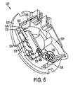
- Brush assembly 520 may include a non-conductive annular ring 522 that acts as a support member for conductive arm 524 and biasing member 528.
- Annular ring 522 may include a first post member 580 and a second post member 542.
- the conductive arm 524 may include a first end portion 530 that is coupled to the first post member 580.
- the first end portion 530 may be shaped to fit at least partially around the first post member 580.
- the first end portion 530 may be substantially circular to fit around a substantially circular first post member 580.
- the first post member 580 may include a protruding member 582 to prevent the first end portion 530 from sliding off of the first post member 580.
- the conductive arm 524 may include a second end portion 532 that is coupled to a brush 526.
- the second end portion 532 may be coupled to the brush 526 as described above such that there is an electrical connection between the second end portion 532 and the brush 526.
- Biasing member 528 may be coupled to the second post member 542.
- the biasing member 528 is a spring. At least a portion of the biasing member may be located below the conductive arm 524.
- the biasing member 528 is coupled to the conductive arm 524 to provide a substantially constant force to bias the brush 526 towards the commutator 516. In one implementation, both the biasing member 528 and the conductive arm 524 each provide a force to bias the brush 526 towards the commutator.
- the brush assembly 520 also may include a conductive connector 590 and a wire 592 (e.g., a braided shunt wire) that electrically couples the conductive arm 524 and the conductive connector 590.
- the conductive connector 590 may be coupled to an electrical connection to the motor such as, for example, by connecting to one or more wires that are coupled to the motor.
Landscapes
- Engineering & Computer Science (AREA)
- Power Engineering (AREA)
- Motor Or Generator Current Collectors (AREA)
- Motor Or Generator Frames (AREA)
- Portable Power Tools In General (AREA)
Applications Claiming Priority (1)
| Application Number | Priority Date | Filing Date | Title |
|---|---|---|---|
| US62701504P | 2004-11-10 | 2004-11-10 |
Publications (2)
| Publication Number | Publication Date |
|---|---|
| EP1657793A2 true EP1657793A2 (de) | 2006-05-17 |
| EP1657793A3 EP1657793A3 (de) | 2008-02-20 |
Family
ID=35828294
Family Applications (1)
| Application Number | Title | Priority Date | Filing Date |
|---|---|---|---|
| EP05024536A Withdrawn EP1657793A3 (de) | 2004-11-10 | 2005-11-10 | Bürstenanordnung mit elastischer Halterung zur Kraftausübung |
Country Status (3)
| Country | Link |
|---|---|
| US (2) | US7432627B2 (de) |
| EP (1) | EP1657793A3 (de) |
| JP (1) | JP2006166698A (de) |
Cited By (1)
| Publication number | Priority date | Publication date | Assignee | Title |
|---|---|---|---|---|
| DE102007044399A1 (de) * | 2007-09-18 | 2009-04-09 | Continental Automotive Gmbh | Vierpoliger elektromotorischer Antrieb mit einem Hammerbürstenhaltersystem |
Families Citing this family (4)
| Publication number | Priority date | Publication date | Assignee | Title |
|---|---|---|---|---|
| DE102006014762A1 (de) * | 2006-03-30 | 2007-10-04 | Robert Bosch Gmbh | Kunststoffelement |
| US8836198B2 (en) * | 2011-09-07 | 2014-09-16 | Taiwan Long Hawn Enterprise Co. | Brush holder of slip ring |
| CN107370004B (zh) * | 2017-07-12 | 2023-05-16 | 河南中烟工业有限责任公司 | 一种集电器碳刷架快速拆卸装置 |
| WO2024084844A1 (ja) * | 2022-10-19 | 2024-04-25 | パナソニックIpマネジメント株式会社 | 電動機 |
Citations (6)
| Publication number | Priority date | Publication date | Assignee | Title |
|---|---|---|---|---|
| US2389941A (en) * | 1944-10-06 | 1945-11-27 | Gen Electric | Brush rigging |
| US2413560A (en) * | 1944-11-03 | 1946-12-31 | Gen Electric | Brush rigging |
| DE8525046U1 (de) * | 1985-09-02 | 1986-06-26 | Siemens AG, 1000 Berlin und 8000 München | Bürstenanordnung für Kommutatormotore |
| US4746829A (en) * | 1986-07-30 | 1988-05-24 | Johnson Electric Industry Manufactory, Limited | Brush gear assembly |
| EP0501839A2 (de) | 1991-03-01 | 1992-09-02 | Westinghouse Electric Corporation | Erdungsbürste und Bürstenhalter für eine Welle |
| US20020047468A1 (en) * | 2000-10-06 | 2002-04-25 | Keung Lee | Motor housing having simplified cover plate and brush base |
Family Cites Families (22)
| Publication number | Priority date | Publication date | Assignee | Title |
|---|---|---|---|---|
| US459581A (en) * | 1891-09-15 | Fishing-reel | ||
| DE312248C (de) | ||||
| DE560230C (de) | 1924-10-28 | 1932-09-29 | Siemens Schuckertwerke Akt Ges | Buerstenanordnung fuer elektrische Maschinen |
| US1794291A (en) * | 1928-08-02 | 1931-02-24 | Hobart Brothers Co | Brush support for electrical apparatus |
| US2325915A (en) * | 1942-04-13 | 1943-08-03 | Singer Mfg Co | Permanent magnet motor |
| US2345428A (en) * | 1942-10-26 | 1944-03-28 | Gen Electric | Electric current collector |
| US2498346A (en) * | 1947-08-12 | 1950-02-21 | Sr William J Smith | Generator and starter |
| US2755399A (en) * | 1952-01-07 | 1956-07-17 | Emerson Electric Mfg Co | Brush holder mechanism |
| US2753477A (en) * | 1953-08-31 | 1956-07-03 | Gen Motors Corp | Electrical brush assembly |
| US2760094A (en) * | 1955-01-03 | 1956-08-21 | Gen Motors Corp | Dynamoelectric machine |
| US3450916A (en) * | 1965-08-18 | 1969-06-17 | Takaichi Mabuchi | Brush supporting means for miniature electric motors |
| US3648086A (en) * | 1968-08-07 | 1972-03-07 | Gen Electric | Starter generator construction |
| JPS4860398U (de) * | 1971-11-09 | 1973-08-01 | ||
| NL8200652A (nl) * | 1982-02-18 | 1983-09-16 | Skil Nederland Nv | Elektromotor met verbeterde borstelkonstruktie. |
| US4741677A (en) * | 1984-11-14 | 1988-05-03 | Fiamm Componenti Accessori S.P.A. | Electrical compressor for motor vehicle horns, comprising an electric motor and air compressor in mutual axial alignment relationship |
| US4638203A (en) * | 1985-06-21 | 1987-01-20 | Matsushita Electric Industrial Co., Ltd. | Attachment structure for brush holder springs |
| JPH0323824Y2 (de) * | 1985-12-09 | 1991-05-23 | ||
| GB2226709B (en) * | 1988-12-30 | 1993-05-26 | Johnson Electric Ind Mfg | Terminal arrangement for an electric motor |
| GB9520389D0 (en) | 1995-10-06 | 1995-12-06 | Johnson Electric Sa | Brush gear for an electronic motor |
| DE10003901B4 (de) * | 2000-01-29 | 2004-02-05 | Schunk Metall Und Kunststoff Gmbh | Tragplatte für zumindest eine Kohlebürste |
| CA2351217C (en) | 2001-06-19 | 2008-12-02 | Teijin Limited | An apparatus for supplying a therapeutic oxygen gas |
| JP4223837B2 (ja) * | 2003-02-28 | 2009-02-12 | 並木精密宝石株式会社 | ブラシ装置及びブラシ付きモータ |
-
2005
- 2005-11-09 US US11/270,877 patent/US7432627B2/en not_active Expired - Fee Related
- 2005-11-10 JP JP2005355392A patent/JP2006166698A/ja not_active Withdrawn
- 2005-11-10 EP EP05024536A patent/EP1657793A3/de not_active Withdrawn
-
2008
- 2008-08-26 US US12/198,445 patent/US7723893B2/en not_active Expired - Fee Related
Patent Citations (6)
| Publication number | Priority date | Publication date | Assignee | Title |
|---|---|---|---|---|
| US2389941A (en) * | 1944-10-06 | 1945-11-27 | Gen Electric | Brush rigging |
| US2413560A (en) * | 1944-11-03 | 1946-12-31 | Gen Electric | Brush rigging |
| DE8525046U1 (de) * | 1985-09-02 | 1986-06-26 | Siemens AG, 1000 Berlin und 8000 München | Bürstenanordnung für Kommutatormotore |
| US4746829A (en) * | 1986-07-30 | 1988-05-24 | Johnson Electric Industry Manufactory, Limited | Brush gear assembly |
| EP0501839A2 (de) | 1991-03-01 | 1992-09-02 | Westinghouse Electric Corporation | Erdungsbürste und Bürstenhalter für eine Welle |
| US20020047468A1 (en) * | 2000-10-06 | 2002-04-25 | Keung Lee | Motor housing having simplified cover plate and brush base |
Cited By (1)
| Publication number | Priority date | Publication date | Assignee | Title |
|---|---|---|---|---|
| DE102007044399A1 (de) * | 2007-09-18 | 2009-04-09 | Continental Automotive Gmbh | Vierpoliger elektromotorischer Antrieb mit einem Hammerbürstenhaltersystem |
Also Published As
| Publication number | Publication date |
|---|---|
| JP2006166698A (ja) | 2006-06-22 |
| US7432627B2 (en) | 2008-10-07 |
| US20060119212A1 (en) | 2006-06-08 |
| EP1657793A3 (de) | 2008-02-20 |
| US20080315712A1 (en) | 2008-12-25 |
| US7723893B2 (en) | 2010-05-25 |
Similar Documents
| Publication | Publication Date | Title |
|---|---|---|
| EP1522127B1 (de) | Bürstenanordnung | |
| US6744170B1 (en) | Brush assembly | |
| US7723893B2 (en) | Brush assembly including biasing member for applying force | |
| JP2768927B2 (ja) | 整流子モータ用カーボンブラシホルダ | |
| CA2961220C (en) | Battery contact with a surface texture | |
| CA2585734C (en) | Power cord system for welding-type devices | |
| JP4638884B2 (ja) | 統合ブラシホルダ保持システム | |
| US5644182A (en) | End cap and brush holder assembly for dynamoelectric machine | |
| CN101588106A (zh) | 电刷装置 | |
| US8487503B2 (en) | Hand power tool with brush motor | |
| US9143015B2 (en) | Brush holder for a brush assembly for a power tool motor | |
| JP4542661B2 (ja) | 電動モータ | |
| US9991770B2 (en) | Spring post for brush card for a power tool | |
| JP7017461B2 (ja) | 電動作業機 | |
| US688817A (en) | Brush-holder. | |
| JPH09201016A (ja) | 回転電機用ブラシ保持装置 | |
| KR19980061363U (ko) | 전동공구용 정류자 모터의 카본 브러시 어셈블리 |
Legal Events
| Date | Code | Title | Description |
|---|---|---|---|
| PUAI | Public reference made under article 153(3) epc to a published international application that has entered the european phase |
Free format text: ORIGINAL CODE: 0009012 |
|
| AK | Designated contracting states |
Kind code of ref document: A2 Designated state(s): AT BE BG CH CY CZ DE DK EE ES FI FR GB GR HU IE IS IT LI LT LU LV MC NL PL PT RO SE SI SK TR |
|
| AX | Request for extension of the european patent |
Extension state: AL BA HR MK YU |
|
| PUAL | Search report despatched |
Free format text: ORIGINAL CODE: 0009013 |
|
| AK | Designated contracting states |
Kind code of ref document: A3 Designated state(s): AT BE BG CH CY CZ DE DK EE ES FI FR GB GR HU IE IS IT LI LT LU LV MC NL PL PT RO SE SI SK TR |
|
| AX | Request for extension of the european patent |
Extension state: AL BA HR MK YU |
|
| 17P | Request for examination filed |
Effective date: 20080314 |
|
| 17Q | First examination report despatched |
Effective date: 20080515 |
|
| AKX | Designation fees paid |
Designated state(s): AT BE BG CH CY CZ DE DK EE ES FI FR GB GR HU IE IS IT LI LT LU LV MC NL PL PT RO SE SI SK TR |
|
| STAA | Information on the status of an ep patent application or granted ep patent |
Free format text: STATUS: EXAMINATION IS IN PROGRESS |
|
| STAA | Information on the status of an ep patent application or granted ep patent |
Free format text: STATUS: THE APPLICATION IS DEEMED TO BE WITHDRAWN |
|
| 18D | Application deemed to be withdrawn |
Effective date: 20170613 |