EP1657799A2 - Dispositif de batterie dans un terminal mobile et procédé d'opération pour celui-ci - Google Patents
Dispositif de batterie dans un terminal mobile et procédé d'opération pour celui-ci Download PDFInfo
- Publication number
- EP1657799A2 EP1657799A2 EP05024696A EP05024696A EP1657799A2 EP 1657799 A2 EP1657799 A2 EP 1657799A2 EP 05024696 A EP05024696 A EP 05024696A EP 05024696 A EP05024696 A EP 05024696A EP 1657799 A2 EP1657799 A2 EP 1657799A2
- Authority
- EP
- European Patent Office
- Prior art keywords
- battery
- mobile terminal
- overheating
- state
- controller
- Prior art date
- Legal status (The legal status is an assumption and is not a legal conclusion. Google has not performed a legal analysis and makes no representation as to the accuracy of the status listed.)
- Withdrawn
Links
Images




Classifications
-
- H—ELECTRICITY
- H04—ELECTRIC COMMUNICATION TECHNIQUE
- H04M—TELEPHONIC COMMUNICATION
- H04M1/00—Substation equipment, e.g. for use by subscribers
- H04M1/02—Constructional features of telephone sets
- H04M1/0202—Portable telephone sets, e.g. cordless phones, mobile phones or bar type handsets
- H04M1/026—Details of the structure or mounting of specific components
- H04M1/0262—Details of the structure or mounting of specific components for a battery compartment
-
- H—ELECTRICITY
- H04—ELECTRIC COMMUNICATION TECHNIQUE
- H04B—TRANSMISSION
- H04B1/00—Details of transmission systems, not covered by a single one of groups H04B3/00 - H04B13/00; Details of transmission systems not characterised by the medium used for transmission
- H04B1/38—Transceivers, i.e. devices in which transmitter and receiver form a structural unit and in which at least one part is used for functions of transmitting and receiving
-
- H—ELECTRICITY
- H01—ELECTRIC ELEMENTS
- H01M—PROCESSES OR MEANS, e.g. BATTERIES, FOR THE DIRECT CONVERSION OF CHEMICAL ENERGY INTO ELECTRICAL ENERGY
- H01M10/00—Secondary cells; Manufacture thereof
- H01M10/42—Methods or arrangements for servicing or maintenance of secondary cells or secondary half-cells
- H01M10/48—Accumulators combined with arrangements for measuring, testing or indicating the condition of cells, e.g. the level or density of the electrolyte
- H01M10/486—Accumulators combined with arrangements for measuring, testing or indicating the condition of cells, e.g. the level or density of the electrolyte for measuring temperature
-
- H—ELECTRICITY
- H01—ELECTRIC ELEMENTS
- H01M—PROCESSES OR MEANS, e.g. BATTERIES, FOR THE DIRECT CONVERSION OF CHEMICAL ENERGY INTO ELECTRICAL ENERGY
- H01M50/00—Constructional details or processes of manufacture of the non-active parts of electrochemical cells other than fuel cells, e.g. hybrid cells
- H01M50/50—Current conducting connections for cells or batteries
- H01M50/569—Constructional details of current conducting connections for detecting conditions inside cells or batteries, e.g. details of voltage sensing terminals
-
- H—ELECTRICITY
- H02—GENERATION; CONVERSION OR DISTRIBUTION OF ELECTRIC POWER
- H02H—EMERGENCY PROTECTIVE CIRCUIT ARRANGEMENTS
- H02H7/00—Emergency protective circuit arrangements specially adapted for specific types of electric machines or apparatus or for sectionalised protection of cable or line systems, and effecting automatic switching in the event of an undesired change from normal working conditions
- H02H7/18—Emergency protective circuit arrangements specially adapted for specific types of electric machines or apparatus or for sectionalised protection of cable or line systems, and effecting automatic switching in the event of an undesired change from normal working conditions for batteries; for accumulators
-
- H—ELECTRICITY
- H02—GENERATION; CONVERSION OR DISTRIBUTION OF ELECTRIC POWER
- H02J—ELECTRIC POWER NETWORKS; CIRCUIT ARRANGEMENTS OR SYSTEMS FOR SUPPLYING OR DISTRIBUTING ELECTRIC POWER; SYSTEMS FOR STORING ELECTRIC ENERGY
- H02J7/00—Circuit arrangements for charging or discharging batteries or for supplying loads from batteries
-
- H—ELECTRICITY
- H04—ELECTRIC COMMUNICATION TECHNIQUE
- H04M—TELEPHONIC COMMUNICATION
- H04M1/00—Substation equipment, e.g. for use by subscribers
- H04M1/02—Constructional features of telephone sets
-
- H—ELECTRICITY
- H04—ELECTRIC COMMUNICATION TECHNIQUE
- H04M—TELEPHONIC COMMUNICATION
- H04M2250/00—Details of telephonic subscriber devices
- H04M2250/12—Details of telephonic subscriber devices including a sensor for measuring a physical value, e.g. temperature or motion
-
- Y—GENERAL TAGGING OF NEW TECHNOLOGICAL DEVELOPMENTS; GENERAL TAGGING OF CROSS-SECTIONAL TECHNOLOGIES SPANNING OVER SEVERAL SECTIONS OF THE IPC; TECHNICAL SUBJECTS COVERED BY FORMER USPC CROSS-REFERENCE ART COLLECTIONS [XRACs] AND DIGESTS
- Y02—TECHNOLOGIES OR APPLICATIONS FOR MITIGATION OR ADAPTATION AGAINST CLIMATE CHANGE
- Y02E—REDUCTION OF GREENHOUSE GAS [GHG] EMISSIONS, RELATED TO ENERGY GENERATION, TRANSMISSION OR DISTRIBUTION
- Y02E60/00—Enabling technologies; Technologies with a potential or indirect contribution to GHG emissions mitigation
- Y02E60/10—Energy storage using batteries
Definitions
- the present invention relates generally to a battery device in a mobile terminal and an operating method thereof, and in particular, to a battery device for use in a mobile terminal, for automatically detaching a battery from the mobile terminal to prevent an accident caused by battery overheating, and a method of operating the battery device.
- Mobile terminals for providing mobile communication services such as CDMA (Code Division Multiple Access), GSM (Global System for Mobile communication), PCS (Personal Communications Service), and PDA (Personal Digital Assistant) phones, are provided with detachable batteries for supplying standby power or operational power.
- the detachable batteries allow users to carry the mobile terminals conveniently and use them at any place.
- a mobile terminal is typically provided with such a battery on one side thereof, for power supply, and the battery will have a different size according to its capacity.
- the mobile terminal needs DC (Direct Current) power to operate.
- the DC power is externally provided to the mobile terminal and, at the same time, it is converted to a predetermined current through a predetermined control and charges the battery.
- the battery is a typically rechargeable, generally of a NiCd (Nickel-Cadmium), NiMH (Nickel-Metal-Hydride) or Li Ion (Lithium-Ion) type.
- Mobile terminals have much circuitry, often include many devices, and emit much heat during a call.
- a NiCd or Li Ion battery is usually used for the mobile terminal. If a call lasting a long time is made through the mobile terminal, the battery will heat up and, in tum, will heat the mobile terminal. This heat from the battery, along with the heat generated inside the terminal, can cause malfunction or communication failure and, at worst, a battery explosion.
- the overheating may occur while the battery is installed in the mobile terminal, which includes a risk of the battery exploding.
- batteries for mobile terminals are typically made as thin and lightweight as possible. As a result, there is a probability that the battery may be damaged or even may explode due to heat from the chemical reaction among electrolytes or due to external shock-incurred mixing of the electrolytes during charging/discharging of the battery.
- a system that senses a change in temperature inside the battery and ensures the safety of the battery by providing a control signal that corresponds with the temperature change.
- the present invention is to substantially solve at least the above problems and/or disadvantages and to provide at least the advantages below. Accordingly, the object of the present invention is to provide a battery device in a mobile terminal for automatically separating a battery from the mobile terminal to avoid danger caused by battery overheating, and a method of operating the battery device.
- a battery state sensor periodically monitors a change in the state of a battery during operation or charging of the battery and outputs a predetermined signal corresponding to the monitored state change
- a controller senses a battery overheating-caused danger from the signal received from the battery state sensor and outputs a control signal
- an automatic locker separates the battery from the mobile terminal according to the control signal received from the controller.
- temperature of a battery is periodically monitored. It is determined whether the mobile terminal is in a battery overheating-caused danger state according to the monitored temperature. If the mobile terminal is in the battery overheating-caused danger state, the battery is released from a locked state and separated from the mobile terminal.
- the present invention is intended to provide a method of preventing danger from battery overheating by automatically detaching the battery from a mobile terminal.
- a hardware modification may be made to easily detach the battery from the mobile terminal by adding a function like a spring to a button that fixes the battery and, a software modification may be made to block power supply from the battery to the components of the mobile terminal as well as controlling the button. Hence, when the danger entailed by battery overheating is sensed, the battery is easily detached from the mobile terminal.
- FIG. 1 is a perspective view of the mobile terminal from which the battery is detached according to an embodiment of the present invention.
- the mobile terminal includes a main body 100, an automatic locker 120 formed on a portion of the main body 100, and a battery 130 detachably fixed on the main body 100 by the automatic locker 120.
- the battery 130 is preferably separated from the main body 100 in a sliding manner.
- the main body 100 may be further provided with an engagement groove in addition to the automatic locker 120, the engagement groove is not provided the present embodiment to allow the battery 130 to automatically slide along the main body 100.
- Battery 130 includes a battery cell mounted inside a battery case having a front case and a rear case.
- a front connector is provided on the battery cell on a lower portion of the front case that is brought into contact with the main body 100.
- a rear connector is formed on a lower portion of the rear case opposite to the front case, for charging the battery cell in contact with a charger terminal (not shown).
- the battery 130 is further provided with a fixing groove formed in an upper portion of the rear case.
- the main body 100 has a connector 110 to contact the front connector of the battery 130.
- the battery 130 is attached onto the main body 100 by means of the automatic locker 120 formed on a portion of the main body 100.
- the automatic locker 120 fixes the battery 130 on the mobile terminal.
- the automatic locker 120 may further include a motor driven by a predetermined control signal so as to automatically push the battery 130 off the mobile terminal, upon sensing battery overheating.
- the automatic locker 120 has a locker portion 140 to release the battery 130 from a locked state by the control signal.
- the locker portion 140 makes the battery slightly bounce by spring action and be slidingly detached from the mobile terminal.
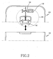
- FIG. 2 is a sectional view of the automatic locker 120.
- the automatic locker 120 includes the locker portion 140, a driving motor 150, and a gear portion 160.
- the locker portion 140 is formed at a predetermined position of the main body 100, for automatically releasing the battery 130 from a locked state with the main body 100 by motor rotation.
- the gear portion 150 is connected to the locker portion 140, for converting the rotational movement of the motor to a linear movement.
- the driving motor 150 rotates in conjunction with the gear portion 160 and is driven by the control signal generated upon sensing battery overheating.
- the automatic locker 120 which functions as a spring, slightly bounces the battery 130 off the mobile terminal by the control signal when a battery overheating-caused danger is sensed.
- the temperature of the battery 130 is continuously monitored during the operation of the mobile terminal. If the temperature is equal to or higher than a predetermined threshold, a driving signal is fed to the driving motor 150, to thereby rotate the driving motor 150. Thus, the gear portion 160 in engagement with the driving motor 150 is operated. The gear portion 160 is interlocked with the locker portion 140 to release the battery 130 from the locked state.
- FIGs. 3A, 3B and 3C are perspective views sequentially illustrating detachment of the battery 130 according to the embodiment of the present invention.
- the battery 130 is attached to the main body 100, as shown in a side view of the mobile terminal in FIG. 3A.
- the locker portion 140 When the locker portion 140 operates, the battery 130 springs up slightly in the direction of A in FIG. 3B.
- the battery 130 is released from its locked state by the locker portion 140, it slides along the main body 100 to be separated, as shown in FIG. 3C.
- the automatic locker 120 is so configured as to instantaneously bounce the battery 130 off the mobile terminal in order to avoid such a danger as explosion caused by battery overheating. While the automatic locker 120 has been described to have the configuration illustrated in FIG. 2, it is not limited to the configuration. Thus, the automatic locker 120 can be configured in any other way as far as it can function as a spring to easily separate the battery 130 from the mobile terminal.
- the battery device operates as follows.
- electrolytes in the battery cell may chemically react, emitting much heat. Exposing the battery 130 to too much shock may mix the electrolytes, resulting in generation of too much heat. The resulting danger such as explosion is prevented by sensing the overheating and quickly and automatically separating the battery 130 from the mobile terminal.
- FIG. 4 is a block diagram of the mobile terminal for automatically detaching the battery according to the embodiment of the present invention.
- a controller 200 receives a predetermined power, processes wireless calls and data in the mobile terminal, and controls each component. That is, the controller 200 provides overall control to the mobile terminal.
- the predetermined power refers to power from a power supply 250.
- the controller 200 monitors the state of the battery 130 and determines whether the battery 130 is overheated. If it is, the controller 200 controls the automatic locker 120 to automatically separate the battery 130 to avoid battery explosion.
- the controller 200 monitors the battery state, for example, the temperature inside the battery 130 at every predetermined time period, in the same manner as voltage monitoring, and determines whether the temperature is equal to or higher than an overheating threshold indicating a danger such as explosion.
- the controller 200 controls a switch 260 to block power from the battery 130 and to disconnect the battery 130 from the mobile terminal.
- the controller 200 controls the automatic locker 120 to slightly bounce the battery 130 off the mobile terminal. That is, the controller 200 analyzes a signal received from a battery state sensor 270 that monitors the battery temperature, senses battery overheating, and outputs a corresponding control signal.
- a display 210 displays screen data corresponding to key input data received from a keypad 220, or displays the operational state of the mobile terminal and other information in icons or characters under the control of the controller 200.
- the display 210 also visually notifies of the function setting or invocation under the control of the controller 200.
- the display 210 can display a message notifying the user of danger that might be caused by battery overheating under the control of the controller 200.
- the keypad 220 includes alphanumerical keys and function keys and provides key input data received form the user to the controller 200. That is, the keypad 220 outputs key input data corresponding to keys pressed by the user to the controller 200.
- the controller 200 determines key inputs from which the key input data have been generated and performs corresponding operations.
- a memory 230 connected to the controller 200 preferably includes a ROM (Read Only Memory) for storing programs and information necessary to control the operation of the mobile terminal, a RAM (Random Access Memory), and a voice memory.
- the memory 230 also stores the overheating threshold as a criterion by which to determine battery overheating under the control of the controller 200.
- the battery 130 includes battery cells for converting between electric and chemical energy, accumulates chemical energy during charging, converts chemical energy to electric energy and provides the electric energy to the power supply 250 during discharging.
- the power supply 250 provides power needed for to operate each component of the mobile terminal from the battery 130.
- the controller 200 Upon receipt of a battery overheating sensing signal from the battery state sensor 270, the controller 200 outputs a control signal for controlling power to each component to the automatic locker 120, so that the battery 130 is automatically separated from the mobile terminal.
- the controller 200 may transmit a control signal directly to the switch 260 according to the output of the battery state sensor 270 so that the switch 260 allows power supply from the power supply 250 to components or blocks the power supply.
- the switch 260 may be implemented in software, for example, by control of a transistor, and functions to disconnect the battery 130 from the main body of the mobile terminal by blocking power supply.
- the switch may be implemented as the automatic locker 120 so as to slightly bounce the battery 130 off and thus separate the battery 130 from the main body of the mobile terminal.
- the battery state sensor 270 periodically monitors the temperature change of the battery and outputs a monitored temperature change by a predetermined signal.
- a thermistor can be used to sense the temperature change of the battery 130.
- the battery state sensor 270 senses the temperature change of the battery 130 as the battery 130 is used or charged, and outputs a corresponding signal to the controller 200. If the battery temperature increases, the battery state sensor 270 reads the increased temperature and outputs to the controller 200 a signal indicating whether the battery temperature is equal to or higher than the overheating threshold in order to avoid battery overheating-caused danger.
- the controller 200 senses battery overheating by analyzing the signal received from the battery state sensor 270 and outputs a corresponding control signal to the switch 260 so that the switch 260 switches off power from the battery 130. Also, the controller 200 can control the automatic locker 120 to automatically separate the battery 130 from the mobile terminal.
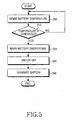
- FIG. 5 is a flowchart illustrating a control operation for preventing battery overheating in the mobile terminal according to the embodiment of the present invention.
- the controller 200 detects the temperature of the battery 130 by controlling the battery state sensor 270 to periodically monitor the battery temperature in step 300.
- the controller 200 compares the detected battery temperature with the overheating threshold at which the battery 130 might explode due to overheating.
- the controller 200 If the battery temperature is lower than the overheating threshold, the controller 200 returns to step 300, considering that the battery temperature is normal. On the other hand, if the battery temperature is equal to or higher than the overheating threshold, the controller 200 displays a message warning of a danger due to the battery overheating on the display 210, or sounds an alarm in step 320.
- step 330 the controller 200 turns off the switch 260 and thus disconnects the battery 130 from the power supply 250, thereby disconnecting the battery 130 from the mobile terminal.
- the controller 200 controls the automatic locker 120 to release the battery 130 from a locked state and the battery 130 slidingly separates from the mobile terminal in step 340.
- FIG. 6 is a flowchart illustrating a control operation for preventing battery overheating in the mobile terminal according to another embodiment of the present invention.
- the controller 200 upon power-on, the controller 200 detects the state of the battery 130 through the battery state sensor 270. The controller 200 receives a signal indicating the value of a current flowing from the battery 130 in step 400 and compares the current with a predetermined threshold in step 410. If the current is equal to or higher than the threshold, the controller 200 warns the user that the battery 130 is in an overcurrent state that might cause a dangerous situation like battery explosion in step 420.
- the controller 200 controls the switch 260 to block the current flowing from the battery 130 according to the number of overcurrent inflows.
- the battery temperature is monitored along with the overcurrent monitoring.
- the controller 200 checks the temperature of the battery 130 in step 430 and compares the battery temperature with the overheating threshold in step 440. If the battery temperature is equal to or higher than the overheating threshold, the controller 200 controls the automatic locker 120 to separate the battery 130 from the mobile terminal in step 450.
- the battery 130 is forcedly disconnected from the mobile terminal through the switch 260 according to the number of overcurrent inflows. At the same time, in a battery overheating situation, the battery 130 is released from a locked state and separated from the mobile terminal.
- the switch upon sensing a dangerous situation caused by battery overheating, the switch is turned off, thereby disconnecting the battery from the mobile terminal.
- the automatic locker is controlled to push the battery off the mobile terminal.
- An advantage with the present invention is that battery overheating is determined through periodic monitoring of battery temperature and thus, upon sensing battery overheating, a battery is automatically separated from a mobile terminal, thereby avoiding battery overheating-caused accidents. Another advantage is that the use of a thermistor for preventing the battery overheating from damaging the battery and mobile terminal circuitry during charging or using the battery reduces product cost.
Landscapes
- Engineering & Computer Science (AREA)
- Chemical & Material Sciences (AREA)
- Chemical Kinetics & Catalysis (AREA)
- Electrochemistry (AREA)
- General Chemical & Material Sciences (AREA)
- Signal Processing (AREA)
- Manufacturing & Machinery (AREA)
- Power Engineering (AREA)
- Computer Networks & Wireless Communication (AREA)
- Charge And Discharge Circuits For Batteries Or The Like (AREA)
- Secondary Cells (AREA)
- Protection Of Static Devices (AREA)
Applications Claiming Priority (1)
| Application Number | Priority Date | Filing Date | Title |
|---|---|---|---|
| KR1020040091721A KR100584404B1 (ko) | 2004-11-11 | 2004-11-11 | 이동 통신 단말기의 배터리 장치 및 그 운용 방법 |
Publications (2)
| Publication Number | Publication Date |
|---|---|
| EP1657799A2 true EP1657799A2 (fr) | 2006-05-17 |
| EP1657799A3 EP1657799A3 (fr) | 2012-11-28 |
Family
ID=35927912
Family Applications (1)
| Application Number | Title | Priority Date | Filing Date |
|---|---|---|---|
| EP05024696A Withdrawn EP1657799A3 (fr) | 2004-11-11 | 2005-11-11 | Dispositif de batterie dans un terminal mobile et procédé d'opération pour celui-ci |
Country Status (4)
| Country | Link |
|---|---|
| US (1) | US7725137B2 (fr) |
| EP (1) | EP1657799A3 (fr) |
| KR (1) | KR100584404B1 (fr) |
| CN (1) | CN1773876A (fr) |
Families Citing this family (19)
| Publication number | Priority date | Publication date | Assignee | Title |
|---|---|---|---|---|
| TWM243862U (en) * | 2003-09-03 | 2004-09-11 | Benq Corp | Mobile phone and battery releasing-device thereof |
| EP2015421B1 (fr) * | 2007-07-13 | 2016-03-09 | Black & Decker, Inc. | Mécanisme de réinitialisation pour bloc-batteries |
| TW200919988A (en) * | 2007-10-26 | 2009-05-01 | Delta Electronics Inc | Wireless communication system and its device |
| US8477041B2 (en) * | 2009-06-29 | 2013-07-02 | Motorola Mobility Llc | Device and method for temperature monitoring and warning |
| US9203937B2 (en) * | 2010-08-05 | 2015-12-01 | Nokia Technologies Oy | Apparatus and method for mobile device speaker port |
| US8470464B2 (en) | 2010-10-14 | 2013-06-25 | Alliant Techsystems Inc. | Methods and apparatuses for electrochemical cell monitoring and control |
| JP5794031B2 (ja) * | 2011-08-08 | 2015-10-14 | 富士通株式会社 | 電子機器、システム、プログラム |
| CN102569931A (zh) * | 2012-02-28 | 2012-07-11 | 深圳市金立通信设备有限公司 | 防止手机电池爆炸的温度检测系统及方法 |
| FR2997800B1 (fr) * | 2012-11-06 | 2015-01-30 | Souriau | Systeme de verrouillage securise et connecteur comportant un tel systeme |
| CN104880262A (zh) * | 2014-02-28 | 2015-09-02 | 鸿富锦精密工业(武汉)有限公司 | 电源过热指示系统 |
| EP2921899B1 (fr) * | 2014-03-21 | 2018-07-04 | Samsung Electronics Co., Ltd | Visiocasque et procédé pour son opération |
| WO2016032525A1 (fr) * | 2014-08-29 | 2016-03-03 | Hewlett-Packard Development Company, L.P. | Déconnecter une batterie d'un système |
| USD728469S1 (en) * | 2014-10-16 | 2015-05-05 | Tzumi Electronics LLC | Battery case for smart phone |
| CN104377390B (zh) * | 2014-11-05 | 2017-03-15 | 上海斐讯数据通信技术有限公司 | 一种基于地理位置改变电池温度上限预警值的系统及方法 |
| KR102239312B1 (ko) * | 2015-01-23 | 2021-04-13 | 주식회사 아모그린텍 | 손목 착용형 전자기기 |
| JP2018067885A (ja) * | 2016-10-21 | 2018-04-26 | ソニー株式会社 | 撮像装置、および撮像方法、並びにプログラム |
| US11128114B2 (en) | 2018-11-13 | 2021-09-21 | Western Technology, Inc. | Hazard detection system for portable electrical devices |
| US12136840B2 (en) * | 2021-12-24 | 2024-11-05 | Motorola Solutions, Inc. | Device, battery and system to control battery power |
| CN116714435A (zh) * | 2023-04-25 | 2023-09-08 | 奇瑞新能源汽车股份有限公司 | 一种电池包弹出系统及控制方法 |
Family Cites Families (12)
| Publication number | Priority date | Publication date | Assignee | Title |
|---|---|---|---|---|
| JPH04233797A (ja) * | 1990-12-28 | 1992-08-21 | Sony Corp | 電子機器保持装置 |
| KR0158845B1 (ko) * | 1995-07-28 | 1999-02-18 | 배순훈 | 리튬건전지의 과부하 방지구조 |
| KR100193736B1 (ko) | 1996-09-17 | 1999-06-15 | 윤종용 | 배터리 보호 기능을 갖는 배터리 팩 |
| US6380710B1 (en) * | 1999-07-09 | 2002-04-30 | Sony Corporation | Photovoltaic-charged secondary battery device |
| US6342826B1 (en) * | 1999-08-11 | 2002-01-29 | Therm-O-Disc, Incorporated | Pressure and temperature responsive switch assembly |
| JP3524827B2 (ja) * | 1999-09-30 | 2004-05-10 | 三洋電機株式会社 | 電話機用電池残量表示装置 |
| JP2001178011A (ja) * | 1999-12-10 | 2001-06-29 | Toshiba Battery Co Ltd | 二次電池装置 |
| CN1269281C (zh) | 2000-03-15 | 2006-08-09 | 三菱电机株式会社 | 电池保护电路 |
| US6570749B1 (en) * | 2000-07-14 | 2003-05-27 | Advanced Battery Technology Ltd | Over-current and thermal protection device |
| US7299373B2 (en) * | 2003-07-01 | 2007-11-20 | Symbol Technologies, Inc. | Systems and methods for a controllable release of power supply in a mobile device |
| US7206567B2 (en) * | 2003-11-10 | 2007-04-17 | Research In Motion Limited | Methods and apparatus for limiting communication capabilities in mobile communication devices |
| JP5196366B2 (ja) * | 2007-11-09 | 2013-05-15 | ソニーモバイルコミュニケーションズ株式会社 | 携帯端末および充電システム |
-
2004
- 2004-11-11 KR KR1020040091721A patent/KR100584404B1/ko not_active Expired - Fee Related
-
2005
- 2005-11-10 US US11/271,696 patent/US7725137B2/en not_active Expired - Fee Related
- 2005-11-11 EP EP05024696A patent/EP1657799A3/fr not_active Withdrawn
- 2005-11-11 CN CNA2005101152430A patent/CN1773876A/zh active Pending
Also Published As
| Publication number | Publication date |
|---|---|
| US7725137B2 (en) | 2010-05-25 |
| CN1773876A (zh) | 2006-05-17 |
| KR100584404B1 (ko) | 2006-05-26 |
| US20060121956A1 (en) | 2006-06-08 |
| EP1657799A3 (fr) | 2012-11-28 |
| KR20060046816A (ko) | 2006-05-18 |
Similar Documents
| Publication | Publication Date | Title |
|---|---|---|
| US7725137B2 (en) | Battery device in a mobile terminal and operating method thereof | |
| US8369904B2 (en) | Cell phone battery system with back-up reserve | |
| US6127801A (en) | Battery pack assembly | |
| US8049464B2 (en) | Rechargeable battery and method for its operation | |
| JP3917099B2 (ja) | Acアダプタ電源装置 | |
| US5705912A (en) | Circuit for preventing overdischarge of rechargeable battery pack consisting of a plurality of rechargeable batteries | |
| EP2105982B1 (fr) | Bloc-batteries | |
| KR100404095B1 (ko) | 휴대용 단말기의 전원 공급 장치 및 방법 | |
| JP5048963B2 (ja) | 電池システム | |
| JP4861245B2 (ja) | 二次電池充電システム | |
| AU2006221628A1 (en) | Bidirectional battery charge controller | |
| EP1343241B1 (fr) | Circuit de protection de batterie | |
| JPH07241040A (ja) | 電池パック及び二次電池の充放電制御方式 | |
| EP1086521B1 (fr) | Chargeur de batterie bifilaire a vitesses multiples | |
| JPH1198702A (ja) | バッテリの異常検出装置及び電池パック | |
| US6518728B2 (en) | Secondary battery device and method of protecting an overdischarge of the same | |
| JP2005051964A (ja) | パック電池の真贋判定方法 | |
| JP2011172311A (ja) | 充電制御装置および電子機器 | |
| KR200227718Y1 (ko) | 리튬이온 배터리의 충전장치 | |
| JP2002330546A (ja) | 電池パック | |
| KR20040105137A (ko) | 이동통신 단말기의 사용자 데이터 손실 방지 제어장치 및그 제어방법 | |
| KR20060073092A (ko) | 이동통신 단말기 및 이의 배터리 관리방법 | |
| JP2003164070A (ja) | 充電器 | |
| KR200278778Y1 (ko) | 랩탑 컴퓨터의 외장형 전원장치 | |
| KR960013699B1 (ko) | 무선전화기에서 충전배터리의 과방전 방지방법 |
Legal Events
| Date | Code | Title | Description |
|---|---|---|---|
| PUAI | Public reference made under article 153(3) epc to a published international application that has entered the european phase |
Free format text: ORIGINAL CODE: 0009012 |
|
| 17P | Request for examination filed |
Effective date: 20051111 |
|
| AK | Designated contracting states |
Kind code of ref document: A2 Designated state(s): AT BE BG CH CY CZ DE DK EE ES FI FR GB GR HU IE IS IT LI LT LU LV MC NL PL PT RO SE SI SK TR |
|
| AX | Request for extension of the european patent |
Extension state: AL BA HR MK YU |
|
| RAP1 | Party data changed (applicant data changed or rights of an application transferred) |
Owner name: SAMSUNG ELECTRONICS CO., LTD. |
|
| PUAL | Search report despatched |
Free format text: ORIGINAL CODE: 0009013 |
|
| AK | Designated contracting states |
Kind code of ref document: A3 Designated state(s): AT BE BG CH CY CZ DE DK EE ES FI FR GB GR HU IE IS IT LI LT LU LV MC NL PL PT RO SE SI SK TR |
|
| AX | Request for extension of the european patent |
Extension state: AL BA HR MK YU |
|
| RIC1 | Information provided on ipc code assigned before grant |
Ipc: H01M 2/10 20060101ALI20121019BHEP Ipc: H02H 7/18 20060101ALI20121019BHEP Ipc: H02J 7/00 20060101AFI20121019BHEP |
|
| AKX | Designation fees paid |
Designated state(s): DE FR GB |
|
| STAA | Information on the status of an ep patent application or granted ep patent |
Free format text: STATUS: THE APPLICATION IS DEEMED TO BE WITHDRAWN |
|
| 18D | Application deemed to be withdrawn |
Effective date: 20130529 |