EP1657958B1 - Système de communication et dispositif d'écoute - Google Patents
Système de communication et dispositif d'écoute Download PDFInfo
- Publication number
- EP1657958B1 EP1657958B1 EP05013793A EP05013793A EP1657958B1 EP 1657958 B1 EP1657958 B1 EP 1657958B1 EP 05013793 A EP05013793 A EP 05013793A EP 05013793 A EP05013793 A EP 05013793A EP 1657958 B1 EP1657958 B1 EP 1657958B1
- Authority
- EP
- European Patent Office
- Prior art keywords
- hearing device
- unit
- output
- hearing
- electrical
- Prior art date
- Legal status (The legal status is an assumption and is not a legal conclusion. Google has not performed a legal analysis and makes no representation as to the accuracy of the status listed.)
- Expired - Lifetime
Links
Images




Classifications
-
- H—ELECTRICITY
- H04—ELECTRIC COMMUNICATION TECHNIQUE
- H04R—LOUDSPEAKERS, MICROPHONES, GRAMOPHONE PICK-UPS OR LIKE ACOUSTIC ELECTROMECHANICAL TRANSDUCERS; ELECTRIC HEARING AIDS; PUBLIC ADDRESS SYSTEMS
- H04R25/00—Electric hearing aids
- H04R25/55—Electric hearing aids using an external connection, either wireless or wired
- H04R25/558—Remote control, e.g. of amplification, frequency
-
- H—ELECTRICITY
- H04—ELECTRIC COMMUNICATION TECHNIQUE
- H04R—LOUDSPEAKERS, MICROPHONES, GRAMOPHONE PICK-UPS OR LIKE ACOUSTIC ELECTROMECHANICAL TRANSDUCERS; ELECTRIC HEARING AIDS; PUBLIC ADDRESS SYSTEMS
- H04R25/00—Electric hearing aids
- H04R25/55—Electric hearing aids using an external connection, either wireless or wired
- H04R25/554—Electric hearing aids using an external connection, either wireless or wired using a wireless connection, e.g. between microphone and amplifier or using Tcoils
-
- H—ELECTRICITY
- H04—ELECTRIC COMMUNICATION TECHNIQUE
- H04R—LOUDSPEAKERS, MICROPHONES, GRAMOPHONE PICK-UPS OR LIKE ACOUSTIC ELECTROMECHANICAL TRANSDUCERS; ELECTRIC HEARING AIDS; PUBLIC ADDRESS SYSTEMS
- H04R25/00—Electric hearing aids
- H04R25/70—Adaptation of deaf aid to hearing loss, e.g. initial electronic fitting
-
- H—ELECTRICITY
- H04—ELECTRIC COMMUNICATION TECHNIQUE
- H04R—LOUDSPEAKERS, MICROPHONES, GRAMOPHONE PICK-UPS OR LIKE ACOUSTIC ELECTROMECHANICAL TRANSDUCERS; ELECTRIC HEARING AIDS; PUBLIC ADDRESS SYSTEMS
- H04R2225/00—Details of deaf aids covered by H04R25/00, not provided for in any of its subgroups
- H04R2225/55—Communication between hearing aids and external devices via a network for data exchange
Definitions
- the present invention is directed to a communication system as well as to a hearing device.
- US 2002/0196955 A1 discloses a voice communication device such as an earpiece that provides for ultra short range transmission of voice sound information using ultra wide band (UWB) radio communications.
- UWB ultra wide band
- Such an earpiece can communicate with other such earpieces and messages or other communications can be routed through other such earpieces.
- US 2005/0069161 A1 discloses a method and apparatus for improving interference suppression processing and control in hearing aids communicating with a mobile station over a short-range wireless network such as a Bluetooth network.
- the hearing aid includes an interference cancelling DSP which receives input audio signals from a microphone system and output audio signals from a Bluetooth module and applies acoustic echo cancellation and interference suppression techniques to suppress acoustic echo and environmental noise.
- a communication system which comprises a wireless transmitter and a wireless receiver whereby the transmitter is built into a hearing device to be worn at one or at both ears of an individual.
- the hearing device has an input acoustical-to-electrical converter unit and an output electrical-to-mechanical converter unit, as well as a signal processing unit, operationally interconnected between the acoustical-to-electrical and the electrical-to-mechanical converter and processing audio representing signals.
- the wireless transmitter is operationally connectable to the output of the input converter unit.
- the communication system further has a receiver which is remote from the hearing device by a distance which is larger than any distance between two areas at one single individual.
- the transmitter and the receiver form commonly a wireless communication link at least for audio representing signals.
- Establishing a wireless communication link from a remote transmitter to a hearing device comprising a receiver and performing communication in a wireless manner is known e.g. from the DE 100 300 915 according to which such communication is established by using Bluetooth technology.
- the present invention resides on the fact of establishing a wireless communication departing from a hearing device as worn by an individual towards receiver unit remote from such individual, thereby transmitting via such wireless link audio representing signals.
- the receiver which is, as was addressed, farer remote from the hearing device with the integrated transmitter than to be possibly worn by the same individual wearing the hearing device, has a wire output and is a part of a further communication link for the addressed at least audio representing signals.
- a wire communication link is established downstream the remote receiver to further transmit the at least audio representing signal, possibly accordingly processed, which was received by the receiver and from the hearing device integrated transmitter.
- the wireless communication link which is established between the hearing device and the addressed remote receiver is only a part of further communication link which additionally has at least one of a further wireless communication link and of a wire bound communication link respectively for the at least audio representing signal.
- the wireless communication link between the hearing device integrated transmitter and the remote receiver is here only part of a wider communication network which may comprise additional links of wireless and/or wire bound type.
- the addressed remote receiver has an output which is operationally connectable to an input of an electrical-to-mechanical converter.
- audio representing signals which are transmitted over the wireless communication link, between hearing device integrated transmitter and remote receiver are, possibly via additional wireless and/or wire bound communication links and possibly differently processed according to the respective communication links, finally communicated to an electrical-to-mechanical converter unit whereat they are reconverted in hearing stimulating signals for one or more than one individuals, exposed to such mechanical signals.
- the electrical-to-mechanical converter unit addressed may thereby be a loudspeaker unit for a group of individuals or may be as will be addressed later an electrical-to-mechanical converter unit as customarily integrated into hearing devices.
- the just addressed electrical-to-mechanical converter unit the input of which being operationally connectable to the output of the remote receiver, forming together with the hearing device integrated transmitter the addressed wireless communication link, is built or integrated into a further hearing device which is to be worn at one or at both ears of a second individual.
- the further hearing device has again an input acoustical-to-electrical converter unit and the addressed electrical-to-mechanical converter unit, the input of which being operationally connectable to the output of the addressed remote receiver, being in fact the output electrical-to-mechanical converter unit of the further hearing device.
- the hearing device with the integrated transmitter may wirelessly communicate via the remote receiver with an output electrical-to-mechanical converter unit of a further hearing device to be worn by a second individual.
- Such second individual wearing the second hearing device may be arbitrarily remote from the individual wearing the hearing device with the integrated transmitter.
- the further individual may thus be in the same room as the first individual wearing the hearing device with the integrated transmitter, may be in a neighbouring room or may be at any other remote distance world-wide and distant from the said first individual.
- the remote receiver which forms, together with the hearing device integrated transmitter, a wireless communication link, is itself integrated into the further hearing device. Thereby wireless communication from transmitter to receiver is established directly between at least two hearing devices.
- the wireless link from hearing device integrated transmitter and remote receiver may only be a part of a further communication link which may include a wide area communication system - WAN -, a local area communication system - LAN -, a signal booster unit, a router unit, etc.
- the wireless communication link between hearing device integrated transmitter and the addressed remote receiver is performed by frequency modulation (FM) thereby including any known and suitable type of such FM modulation in its most generic meaning, or by any digital modulation scheme such as phase shift keying (PSK), Q-ary amplitude modulation (QAM), ect, or is established making use of ultra-wide-band technology (UWB).
- FM frequency modulation
- PSK phase shift keying
- QAM Q-ary amplitude modulation
- ect ultra-wide-band technology
- both hearing devices which were formerly addressed have respectively a receiver and a transmitter integrated.
- the one hearing device to be worn at one or at both ears of the one individual has, additionally to the transmitter, a wireless receiver with an output which is operationally connected to the input of the electrical-to-mechanical converter unit of this one hearing device.
- the further hearing device to be worn at one or both ears of a second individual has a wireless transmitter - additionally to a receiver - which is connectable to the output of the input acoustical-to-electrical converter unit of this further hearing device.
- the wireless transmitter at this further hearing device and the wireless receiver at the one hearing device allow a communication link to be established for at least audio representing signals, from said transmitter of the further hearing device to the receiver of the one hearing device.
- a bi-directional communication becomes possible for the addressed at least audio representing signals.
- the output of the acoustical-to-electrical converter unit of the one and of the at least one further hearing devices are operationally connected to inputs of a computing unit.
- the computing unit generates in dependency from signals which are input to the addressed inputs of the computing unit, at least one computing results at least audio representing signals at an output.
- the output of a computing unit is operationally connected to the input of at least one of the wireless receivers which are provided at the one and the at least one further hearing devices. Further, the output of this addressed at least one wireless receiver is operationally connected to the input of the output electrical-to-mechanical converter of at least one of the one and of the further hearing devices.
- computing unit receives from at least two hearing devices respectively perceived audio representing signals. From these at least two input signals a result audio representing signals is computed. This result audio representing signal is retransmitted to at least one, possibly to both hearing devices so that at least one, possibly both hearing devices transmit to the respective individuals, via their respective electrical-to-mechanical output converter unit, a signal which results from computing acoustical signals perceived at both or at least two hearing devices. Clearly the retransmitted audio representing signal will be an improved signal with an improvement which results from computing commonly both input signals to the computing unit.
- the output of the addressed acoustical-to-electrical converters are operationally connected to the inputs of the computing unit.
- this is performed in that at least one of the addressed operational connections comprises the wireless transmitter of the respective hearing device.
- the computing unit performs a selection between the signals which are applied to its inputs and according to at least one selection criterion.
- selection criterion may e.g. be signal-to-noise ratio.
- the computing unit thereby generates at its output an output signal which accords to one of the input signals as selected.
- the computing unit further controls at least one of the electrical-to-mechanical output converter units, provided at the one and the further hearing devices to be operationally connected to the output of the computing unit.
- the computing unit performs signal selection dynamically in time. This means that whenever the input signals change the selection of the "best-suited" signal may change as well. Analogically dynamic selection may be performed upon variation in time of the selection criterion. Thus during a first time span signal-to-noise ratio may be selection criterion whereas in a second time span e.g. loudness of acoustical signals may be the selection criterion.
- the computing unit may generate an output signal which is not a selection between the input signals as was just discussed, but which is an audio representing signal depending on both input signals.
- an output signal which is not a selection between the input signals as was just discussed, but which is an audio representing signal depending on both input signals.
- the computing unit may e.g. be conceived to perform beam forming. Exploiting input signals which in fact come from remotely located hearing devices, which are mutually distant far more than multiple microphones might be distant in a single hearing device, leads to improved possibilities of beam forming.
- the communication system according to the present invention making use of the computing unit clearly may incorporate more than two hearing devices with their respective acoustical-to-electrical converters, it becomes clear that computation may be performed with respect to the output signals of more than two of these acoustical-to-electrical converter units, which further largely increases the possibilities of improved signal processing.
- communication from one hearing device to a remote further hearing device may be performed in a manner hopping from one hearing device to the next in a chain of hearing devices.
- Each of the intermediate devices forms a signal booster unit, possibly without the respective individual becoming aware that its hearing device is being used as signal booster unit.
- the system comprises more than two hearing devices.
- a transmitter of a first hearing device is operationally connected to the output of its input acoustical-to-electrical converter unit.
- the output of the addressed transmitter is operationally linked by the wireless link to the receiver of the second hearing device.
- the output of this receiver is operationally connected to the input of the transmitter at the same hearing device so that in fact the signal received by the receiver is looped to that transmitter.
- the output of the transmitter of the just addressed hearing device is operationally linked, including wireless communication, to the receiver of a third hearing device.
- the one or at least one of the hearing devices is a hearing aid device.
- the one or the two or more than two hearing devices is or are outside the ear hearing devices and/or in the ear hearing devices and/or completely in the ear canal hearing devices.
- a multiple hearing device communication system may incorporate all the variety of different types of hearing devices, thus e.g. hearing devices for normal hearing individuals, hearing aid devices, binaural hearing devices, provided as outside the ear and/or as in the ear and/or as completely in the ear canal device types.
- a hearing device to be worn by an individual at one or at both of its ears which comprises an input acoustical-to-electrical converter units/an output electrical-to-mechanical converter unit and a wireless transmitter.
- the input of the wireless transmitter is operationally connectable to the output of the input acoustical/mechanical converter unit whereby the transmitter generates a wirelessly transmitted signal for a transmission range of at least 2m.
- this hearing device allows reception of signals from the wireless transmitter in a range of at least 2m which is normally significantly larger than the range between devices worn at one individual's body as e.g. binaural devices.
- the hearing device comprises a wireless receiver.
- the output of such receiver is operationally connected to the input of the output electrical-to-mechanical converter unit.
- the transmitter generates transmitted signals using carrier-based analog or digital modulation schemes such as frequency modulation (FM), phase modulation (e.g. PSK) or amplitude modulation (e.g. QAM) or based on carrierless ultra-wide band techniques, (UWB) employing e.g. on/off keying (OOK), pulse position modulation (PPM) or pulse amplitude modulation (PAM).
- FM frequency modulation
- PSK phase modulation
- QAM amplitude modulation
- UWB carrierless ultra-wide band techniques
- OFK on/off keying
- PPM pulse position modulation
- PAM pulse amplitude modulation
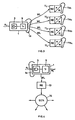
- the communication system comprises a hearing device 1.
- the hearing device 1 comprises an acoustical-to-electrical converter unit 3.
- the electrical output of unit 3 is operationally connected, via a signal processing unit 5, to the input of an output electrical-to-mechanical converter unit 7.
- Input to device 1 are surrounding acoustical signals A 1 , output from device 1 a mechanical signal M 1 as a stimulus to an individual's - 1a - ear.
- the hearing device 1 as an essential part of the communication system according to the present invention has a transmitter unit 9 whereat audio representing signals, which may be dependent from input acoustical signals A 1 , are input.
- transmitter unit 9 such audio representing signals are converted into wireless transmission signals WL.
- the transmitter unit 9 generates a signal WL for longer range transmission e.g. for a range of at least 2m, larger than necessary for reaching any target area at the individual 1a.
- the wireless transmission signal WL at least a part of a communication link CL is established between the hearing device 1 and at least one listening device 11.
- the communication link CL which is formed by or which comprises the wireless communication link WL
- at least audio representing signals perceived at the one individual 1a with the help of the hearing device 1 are transmitted to at least one listening device 11 remote from the individual 1a.
- the device 11 stimulates hearing of at least one further individual 11a.
- the communication link CL consists, in minimum configuration, just of the wireless communication link WL established from the transmitter unit 9 of the hearing device 1 to a respective remote receiver unit 13 at the listening device 11, schematically shown in fig. 2 . Thereby the communication range is restricted to the wireless transmission range of the transmitter unit 9.
- a situation in which the system as of fig. 3 may also be useful is e.g. when a group of individuals 11 a1 to 11 a4 is led by a guide individual 1a through an exhibition.
- the communication link WL may be just a part of a complex communication network.
- the communication link or network CL, comprising wireless link WL may include any known wireless or wire bound communication devices or structures, including e.g. wide area networks - WAN - local area network - LAN -, signal booster units, router units, signal processing units etc.
- the audio representing signal transmitted by the wireless link WL can be transmitted to one or more than one listening devices 11 situated anywhere up to worldwide.
- the leading device 1 of an individual 1a communicates by the wireless link WL with the remote receiver unit 13 situated in a range easily bridgeable by the signal transmitted from transmitter unit 9 of hearing device 1.
- the audio representing signal as received is fed into a communication network CN, 14 which may incorporate any wireless and wire bound communication link to one or more than one ear, remote and/or far-remote listening device for respective individual's or groups of individuals.
- the receiving listening device 11 may thereby just be a loudspeaker unit 11 by which one or more than one individual 1a listens to the audio signals perceived by the individual wearing the hearing device 1 with transmitter unit 9.
- the listening device 11 is realized by at least one further hearing device 2.
- the electric audio representing signal which is transmitted by the transmitter unit 9 of hearing device 1 may be derived directly from the output of the input acoustical-to-electrical converter unit 3 or may be derived from a signal which has already been processed by one or more than one stages of the signal processing unit 5 or may be derived from the input to the output electrical-to-mechanical converter unit 7.
- the electric audio representing signal which is transmitted by the transmitter unit 9 of hearing device 1 may be derived directly from the output of the input acoustical-to-electrical converter unit 3 or may be derived from a signal which has already been processed by one or more than one stages of the signal processing unit 5 or may be derived from the input to the output electrical-to-mechanical converter unit 7.
- hearing device 1 is a hearing aid device and thus provides for an individualized signal transfer function from the output of input converter unit 3 to input of output converter unit 7, it might be advisable to transmit by means of transmitter unit 9 substantially unprocessed output signals of the input converter unit 3. If individual 1a has normal hearing abilities and this hearing device 1 is substantially not individualized as a hearing aid device, it might be advisable to transmit by the transmitter unit 9 rather audio according to signals representing signals as applied to the input of the output converter unit 7.
- the listening device 11 as of fig. 1 is here realized by a second hearing device 2 which again may be one of the devices falling under the definition of "hearing devices" given above.
- transmitter unit 9 of hearing device 1 the audio representing signal is transmitted via the wireless communication link WL finally to an input I 2 of the second hearing device 2.
- this transmitted audio representing signal is generically fed to the output electrical-to-mechanical converter 7 2 of hearing device 2 and thus, an output mechanical signal M 2 is generated as a hearing stimulus signal to a second individual 2a remote from the individual 1a wearing hearing device 1.
- hearing device 2 in its intrinsic mode of operation transmits acoustical input signals A 2 to the electrical-to-mechanical converter unit 7 2 , it might be advisable to provide a control unit 15.
- control unit 15 the individual carrying the second hearing device 2 or another controlling instance may select whether such individual shall listen to the acoustical signals A 2 or shall be switched to a "slave" mode i.e. on the acoustical perception of hearing device 1 acting as a "master" hearing device.
- the control as to which hearing device shall act as a master device for one or more than one further hearing devices is performed by a control unit 15 at the respective hearing devices manually or automatically e.g. by evaluating which of the hearing devices of the communication system at least momentarily experiences optimum or pre-selected acoustical conditions and selecting such a device at least momentarily as a master device.
- the overall communication link CL may be realized just by the wireless communication link WL or, in a combination with such wireless link WL additional communication links which includes at least one wire bound and/or wireless communication link.
- master hearing device 1 communicating exclusively by the communication link WL with one or more than one slave hearing devices 2, 2 1 .
- the communication link is established from the transmitter unit 9 of hearing device 1 to wireless receivers 17 in the further hearing devices 2, 2 1 .
- the output signals of the receiver unit 17 respectively, is operationally connected to the input of respective output electrical-to-mechanical converter unit 7 2 .
- the communication system between a master hearing device 1 and one or more than one slave hearing devices 2 is established by a communication link CL which consists exclusively of multiple wireless communication links.
- the overall communication link is established by the communication link WL from transmitter unit 9 of hearing device 1 to a signal booster unit 19 and from there, via a further wireless link WL' to the receiver unit 17 of one or more than one slave hearing devices 2, 2 1 .
- unit 19 as shown in fig. 7 may be, as shown in this figure, just a signal booster unit or may be a router unit, routing incoming signals to several output signals.
- hearing device 1 acts as master. It dispatches signals according to the acoustical surrounding A 1 to further individuals and their respective hearing devices 2, being switched or controlled in slave mode. Thereby they process, as input signals, audio representing signals, representing or depending on A 1 .
- the hearing device 1 communicates by the integrated transmitter unit 9 wirelessly, and directly (a) with one or more than one hearing devices 2 worn by different remote individuals. Further or alternatively the hearing device 1 communicates by a wireless link from the transmitter unit 9 to a signal booster/router unit 21 directly, from which unit 21 the wirelessly received audio representing input signal is transmitted e.g.
- wire bound (b) to a wide or local area network and/or e.g. wirelessly (c) to one or more than one remote hearing devices 2 (c) and/or e.g. wire bound (d) to one or more than one general listening devices 11, and/or e.g. again wirelessly (e) with a further signal booster/router unit 23, which latter unit 23 distributes the signal still dependent on the acoustical signal A 1 as perceived by hearing device 1 to further units e.g. a registering unit 25 by wire bound link (f) and/or e.g. a displaying unit (27) as a laptop, by wireless link (g).
- audio representing signals according video signals as of handicams may be transmitted to a video displaying unit as to units 27 in fig. 8 .
- the communication system according to the present invention Whenever the communication system according to the present invention is established between at least two hearing devices, it opens a large number of additional possibilities to improve hearing of individuals wearing a hearing device which is part of the communication system.
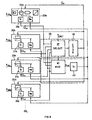
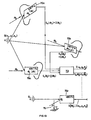
- FIG. 9 there is shown, by means of a simplified functional block/signal-flow diagram, one possible communication system according to the present invention whereat, principally, more than one hearing devices at respective individuals are exposed to about the same acoustical surrounding e.g. in a conference room at different locations.
- the optimally exposed hearing device is momentarily selected as the master and the other hearing devices are switched to slave mode.
- the acoustical surrounding changes e.g. changing speaker individual, automatically the respectively optimum hearing device is reselected as a master and accordingly the other hearing devices are switched to slave mode.
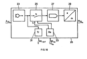
- each of the hearing devices 20 a ... 20 d ... 20 x is conceived as schematically shown at device 20 in figure 10 .
- a hearing device 20, as applied to a communication system as shown in fig. 9 comprises according to fig. 10 and in analogy to the hearing device 1 of fig. 1 , an input acoustical-to-electrical converter 23, operationally connected to a mode-control unit 25.
- the output of the mode-control unit 25 is operationally connected to signal processing unit 27 the output thereof being operationally connected to an output electrical-to-mechanical converter unit 29.
- the hearing device 20 has a transmitter unit 31.
- the transmitter unit 31 transmits wirelessly signals which are dependent from the acoustical input signals A 20 and therefore the input of the transmitter unit 31 is e.g. operationally connected to the output of the acoustical/ electrical converter unit 23.
- the hearing device 20 has a receiver unit 33, wirelessly receiving at least audio representing signals.
- the output of receiver unit 33 is operationally connectable to output connecter unit 29, instead of the output signal dependent on the output of the acoustical-to-electrical converter 23.
- the mode-control unit 25 controls, as schematically shown by switch S, whether the output signal of the acoustical/ electrical converter 23 is, via processing unit 27, operationally connected to converter unit 29 or whether the output signal of receiver unit 33 is operationally connected, possibly via the signal processing unit 27, to said electrical-to-mechanical output converter unit 29.
- the receiver 33 is adapted to receive, besides of wirelessly communicated audio representing signals WL IN , control signals C IN which are separated by respective decoding and applied to control input C of the mode-control unit 25.
- control signals C IN which are separated by respective decoding and applied to control input C of the mode-control unit 25.
- the hearing device of fig. 10 is adapted to be operative as a master hearing device or as a slave hearing device.
- each hearing device 20 a to 20 d communicates by a respective communication link CL a to CL d , including the wireless communication link WL OUT according to fig. 10 , with a control unit 35 shown in fig. 9 within dashed lines.
- the wireless communication link WL OUT are shown in rigid straight lines.
- audio representing signals according to signals A 20a to A 20d are simultaneously transmitted as they occur to a selection unit 37 of control unit 35.
- selection unit 37 all the signals transmitted via the respective wireless transmitter units 31 a to 31 d are evaluated with respect to predetermined criteria.
- Such criteria may e.g. be or comprise signal-to-noise ratio.
- Such criteria are input to unit 37 via input CRIT.
- the selection unit 37 selects one of the input signals as the optimum signal. Once such optimum signal is selected, the information as of which signal has been selected is entered to a coding unit 39 where a control signal C IN is generated.
- the output control signal C IN acts on each of the mode control units 25 a to 25 d of the respective hearing devices 20 a to 20 d and thereby switches all the units 25 a to 25 d to operationally connect, as shown in fig. 10 , a respective receiver unit 33 instead to the respective input acoustical-to-electrical converter unit, to the respective output electrical-to-mechanical converter unit 29, as via respective signal processing unit 27.
- control signal C IN is most preferably transmitted to the respective hearing devices via a control signal communication link which at least includes the wireless communication link to the respective receiver units 33 at the hearing devices 20.
- the signal transmitted via the respective communication link CL having been selected as optimum by action of the selection unit 37.
- the selection unit 37 controls a multiplexing unit 41 by which the selected audio representing signal is output as shown in figure 9 as S opt .
- this signal S opt is transmitted to the receiver units 33 especially of all those hearing devices 20, the signals output at the respective transmitter units 31 not having been selected as optimum.
- the hearing devices according to fig. 9 three receive the audio representing signal of the forth, which has been selected as optimally perceiving according to the criteria set in selection unit 37.
- control unit 35 has a transmitter unit 43 which converts S opt in a wirelessly transmitted output signal, transmitted to all or at least to three of four receiver units 33 of the hearing devices 20 a to 20 d .
- each hearing device may e.g. send together with the audio representing signal an identification code.
- the best signal under the constraint of the criteria as preset in selection unit 37, is evaluated and therewith one transmitting hearing device. That hearing device may be maintained in that operating mode whereat the input acoustical-to-electrical converter unit is operationally connected to the output electrical-to-mechanical converter. All the other hearing devices are switched to the mode wherein the respective output electrical-to-mechanical converter is operationally connected to the output of the receiver unit which receives, wirelessly, signals according to the acoustical signal perceived by the addressed one hearing device.
- control unit 35 has been shown as a unit separate from the hearing devices 20. Thereby this shall not be limiting in that such control unit 35 may be integrated into one or more than one of the hearing devices participating in the communication system network.
- the hearing devices are conceived to comprise a transmitter unit, as of unit 31 of fig. 10 , and a receiver unit, as of unit 33 of fig. 10 , and further are controllable as by the control unit 25 in to "intrinsie" perception mode as well as into “slave” mode, a huge number of different communication systems may be realized, as becomes clear to the skilled artisan reading the present teaching.
- a communication system which makes use of a "device hopping" architecture may be realized as shown in figure 11 .
- the hearing devices 40 a to 40 c comprise each, as was already discussed, an input acoustical-to-electrical converter unit 43 a to 43 c , operationally connected to respective processing units 47 a to 47 c , latter to respective output electrical-to-mechanical converter units 49 a to 49 c .
- a mode-control unit 45 a to 45 c which controllably interconnects, for different operating modes, on one hand the respective transmitter unit 41 a to 41 c , receiver units 43 a to 43 c with the respective signal processing unit 47 a to 47 e and, on the other hand, the respective receiver unit 43 a to 43 c with the respective transmitter unit 41 a to 41 c with each others as will be explained.
- the mode control units 45 a to 45 e are controlled as schematically shown at control inputs C a to C c which may be done e.g. from a central control (not shown) unit, governing operating modes of the hearing devices in the communication system. Such control is most preferably performed in wireless communication.
- a first hearing device 40 a worn by a first individual is operated in the following manner:
- the wirelessly transmitted output signal of transmitter 41 a is received at the second hearing device 40 b .
- This second hearing device is operated as follows:
- the third hearing device 40 c is operated as follows:
- the third hearing device 40 c operates in slave mode with hearing device 40 a as a master, the second hearing device 40 b acting as a transit or booster station for the signal transmission.
- the hearing devices of two or even more than two individuals are commonly exploited to result in an audio representing signal which is improved with respect such signals at each of the separately considered hearing devices.
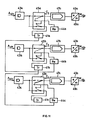
- Each of the four exemplified hearing devices 50 a to 50 d comprises respectively an input acoustical-to-electrical converter 53 a to 53 d the output thereof operationally acting via a respective mode control unit 55 a to 55 d on a respective signal processing unit 57 a to 57 d .
- the outputs of the signal processing units respectively are operationally connected to the output electrical/mechanical converter units 59 a to 59 d .
- each of the hearing devices has a respective transmitter unit 51 a to 51 d , to which signals which accord with a respectively input acoustical signal Asoa to A 50d are fed.
- the transmitter units 51 a to 51 d wirelessly transmit at least audio representing signals.
- the hearing devices 50 a to 50 d further comprise receiver units 54 a to 54 d at least for audio representing signals which are wirelessly transmitted.
- the output of units 54 a to 54 d are respectively operationally connected to respective inputs of the signal processing units 57 a to 57 d .
- the respective control units 55 a to 55 d control in this specific embodiment whether, at a hearing device considered, audio representing signals according to the acoustical surrounding shall be processed or whether audio representing signals as received by the receiver unit shall be processed.
- all the hearing devices 50 a to 50 d are operated in that mode wherein the outputs of the respective receivers 54 a to 54 d are operationally connected to the inputs of the respective signal processing units and thus to the outputs of the respective electrical-to-mechanical converter units 59 a to 59 d .
- the computing unit 61 may thereby be a beam forming unit BF wherein from the input audio representing signals a single output audio representing signal is generated.
- the computing unit 61 there is generated a result audio representing signal which is improved compared with any such signal generated at respective single hearing devices, due to the fact that by the mutually distant input acoustical-to-electrical converter units at separate individuals, improved beam forming becomes possible.
- all input signals may additionally be evaluated according to specific criteria e.g. signal-to-noise ratio.
- the output of the computing unit 61 is operationally connected to a transmitter unit 63 by which the result signal S COMB is transmitted to all the receiver units 54 a or 54 d of the hearing devices. All the hearing devices according to example of fig. 12 are fed with the result audio representing signal. Thereby fig. 12 shows one possible embodiment out of a number of such embodiments where the acoustical perception ability of two or more than two hearing devices which are worn by different individuals are combined to result in an optimized result signal to be retransmitted to a predetermined number or to all of the hearing devices which participate in the communication system according to the present invention.
- computing unit 61 and transmitter 63 remote from any hearing device is only one possible realization form.
- Such computing unit may be incorporated in one or more than one of the hearing devices.
- the transmitter unit 63 may thus be one of the transmitter units which are already integrated in the hearing devices.
- control of the mode-control units 25, 45 and 55 may be performed e.g. from a central control unit or from a leading hearing device or decentralised by each participating hearing device; such control may be performed as a function of momentary reception characteristics of the involved hearing devices.
- Hearing devices may also use a combination of acoustical and/or electrical signals or other information to determine their relative position to one another, e.g. by measuring time delays of signal reception, ect., in order to e.g. form appropriate beam former or select an appropriate input signal.
- appropriate externalisation i.e. application of correct head related transfer function, HRTF
- HRTF head related transfer function
- three hearing devices 70 a to 70 c are operating in a communication system as was described in each embodiment according to the figures 1 to 12 .
- all the three hearing devices 70 a to 70 c are exposed to an acoustical source Q they are under real life conditions, exposed to such source Q under different spatial angles. This dependent from the momentary position of the respective individual's head carrying the respective hearing devices.
- Each of the hearing devices 70 a to 70 c experiences the source Q under a specific direction of arrival, which is, in fig. 13 , addressed generically by the angle ⁇ a to ⁇ c .
- Each of these directions of arrival are mutually independent or with some degree of dependency, if e.g. the source Q itself is moving.
- the acoustical signals perceived by the hearing device 70 a to 70 c are weighted by the individual "head related transfer functions" HRTF a ( ⁇ a ) to HRTF c ( ⁇ c ), which are dependent from the direction of arrival ⁇ a to ⁇ c respectively.
- Techniques are known as e.g. from the WO 00/68703 of the same applicant as the present invention, to determine, at a hearing device considered, the direction of arrival of acoustical signals and thus of ⁇ a to ⁇ c .
- the skilled artisan knows how to determine at the respective hearing devices of fig. 13 the direction of arrival ⁇ .
- this direction of arrival ⁇ at the respective hearing devices incorporated in the communication system of the present invention is known and the individual head related transfer function HRTF ( ⁇ ) as well and is e.g. stored in each of the individual's hearing devices 70 a to 70 c , the value of such head related transfer function at each hearing device and at each individually experienced direction of arrival ⁇ a to ⁇ c is known as well.
- this amplification function which is dependent from direction of arrival namely the head related transfer function HRTF ( ⁇ ) at each of the hearing devices the perceived acoustical signal is de-individualized in that at each hearing device, as an example, there is calculated e.g.
- ⁇ o may e.g. accord with a direction straight in front of the respective individual.
- the audio representing signals which are wirelessly transmitted are de-individualized with respect to amplification as shown by S a ( ⁇ o ) to S c ( ⁇ o ).
- the signals are transmitted to a generic unit 73 representing a generical further treatment of these signals S ( ⁇ o ) as applied according to the present invention.
- audio representing signals which are wirelessly transmitted from respective hearing devices and which depend from acoustical signals impinging upon the addressed hearing device may be individualized by taking into account, at each of the hearing devices, the individual's HRTF functions.
- the spatial location of signal source Q is determined within the space acoustically "monitored" by the hearing devices 70 a to 70 c .
- the spatial location of source Q e.g. with coordinate X q , y q , z q may be calculated. This is done e.g. at unit 73.
- information is available about location of source Q, addressed in fig. 13 by I (X q , y q , z q ) and the individualized signals S a ( ⁇ o ) to S c ( ⁇ o ).
- Re-individualization of the audio representing signals sent to the listening device 70 r as a receiver device may be done at this device by weighting such signals by the head related transfer function HRTF r of the individual wearing the device 70 r e.g. by additionally monitoring the spatial angle of device 70 r with respect to virtual source Q v or absolutely in space, as shown at 76. This may e.g. be done by monitoring head movement of the individual carrying the receiver device 70 r .
Landscapes
- Engineering & Computer Science (AREA)
- Physics & Mathematics (AREA)
- Health & Medical Sciences (AREA)
- General Health & Medical Sciences (AREA)
- Neurosurgery (AREA)
- Otolaryngology (AREA)
- Computer Networks & Wireless Communication (AREA)
- Acoustics & Sound (AREA)
- Signal Processing (AREA)
- Circuit For Audible Band Transducer (AREA)
- Telephone Function (AREA)
- Mobile Radio Communication Systems (AREA)
- Near-Field Transmission Systems (AREA)
Claims (17)
- Système de communication comprenant un émetteur sans fil (9) et un récepteur sans fil, ledit émetteur sans fil (9) étant incorporé dans un dispositif auditif (1) destiné à être porté à une ou aux deux oreilles d'un individu (1a), ledit dispositif auditif (1) améliore 1a faculté auditive d'un individu et ayant :• une unité de convertisseur acoustique-à-électrique (3) pour convertir des signaux acoustiques des alentours de l'individu (1a) dans des signaux électriques à une sortie de ladite unité de convertisseur acoustique-à-électrique (3);• une unité de convertisseur électrique-à-mécanique (7) pour convertir des signaux électriques à une entrée de ladite unité de convertisseur électrique-à-mécanique (7) dans des signaux mécaniques apercevable par dudit individu à une sortie de ladite unité de convertisseur électrique-à-mécanique (7) ;• une unité de traitement de signal (5) pour traiter des signaux électriques d'une sortie de ladite unité de convertisseur (3) appliquée à une entrée de ladite unité de traitement de signal (5) pour en résulter des signaux électriques à une entrée de ladite unité de traitement de signal (5) appliqué sur ladite entrée de ladite unité de convertisseur électrique-à-mécanique ;ledit émetteur sans fil (9) étant fonctionnellement reliable à ladite sortie de ladite unité de convertisseur acoustique-à-électrique (3) afin de transmettre des signaux acoustiques convertis desdits alentours de l'individu (1a), ledit récepteur sans fil étant à distant de ladite dispositif auditif (1) par une distance plus grande qu'une distance quelconque entre deux régions à un individu singulier, ledit émetteur sans fil (9) et ledit récepteur sans fil étant adapté pour former une liaison de communication sans fil (WL) au moins pour des signaux représentant des signaux audio, une sortie dudit récepteur sans fil étant fonctionnellement reliable à une entrée d'une unité de convertisseur électrique-à-mécanique (72) qui est incorporé dans un dispositif auditif supplémentaire (2) destiné à être porté à une oreille ou aux deux oreilles d'un deuxième individu (2a), ledit dispositif auditif supplémentaire (2) de plus ayant une unité de convertisseur acoustique-à-électrique (32) avec une sortie, caractérisé en ce que ladite sortie de ladite unité de convertisseur acoustique-à-électrique (3) dudit dispositif auditif (1) et ladite sortie de l'unité de convertisseur acoustique-à-électrique (32) dudit dispositif auditif supplémentaire (2) sont fonctionnellement reliées aux entrées d'une unité de calcule (52), ladite unité de calcule (52) étant adaptée à performer une sélection entre des signaux appliqués aux entrées de ladite unité de calcule (52) selon au moins un critère de sélection, ledit critère de sélection étant le rapport signal-bruit, et pour générer à une sortie de ladite unité de calcule (52) un signal sélecté, ladite unité de calcule (52) étant de plus adaptée pour contrôler une unité de convertisseur électrique-à-mécanique (7) dudit dispositif auditif (1) et/ou ladite unité de convertisseur électrique-à-mécanique (72) dudit dispositif auditif supplémentaire (2) à être fonctionnellement connecté à ladite sortie de l'unité de calcule (52).
- Le système selon la revendication 1, le récepteur sans fil ayant une sortie de communication à fil et étant une partie d'une liaison de communication supplémentaire au moins pour des signaux représentant des signaux audio.
- Le système selon une des revendications 1 ou 2, la liaison de communication sans fil (WL) étant une part d'une liaison de communication supplémentaire, qui de plus comprend une liaison additionnelle une liaison de communication sans fil supplémentaire et/ou une liaison de communication liée à fil, respectivement au moins pour des signaux représentant des signaux audio.
- Le système selon la revendication 1, le récepteur sans fil étant incorporé dans dudit dispositif auditif supplémentaire (2).
- Le système selon la revendication 3, ladite liaison de communication supplémentaire inclut un système de communication de réseau à grande distance - WAN -, et/ou un système de communication de réseau local - LAN -, une unité de signal booster, une unité de routeur, une unité de traitement de signal.
- Le système selon une des revendications 1 à 5, ladite liaison de communication étant de type de modulation de fréquence - FM - ou de type d'ultra-large bande - UWB.
- Le système selon une des revendications 1 ou 4, ledit dispositif (1) destiné à être porté à une ou aux deux oreilles dudit individu (1a) ayant un récepteur sans fil avec une sortie fonctionnellement reliable à ladite entrée de l'unité de convertisseur électrique-à-mécanique (7) dudit dispositif auditif (1), ledit dispositif auditif supplémentaire (2) destiné à être porté à une ou aux deux oreilles d'un deuxième individu (2a) a un émetteur sans fil reliable à ladite sortie de l'unité de convertisseur acoustique-à-électrique (32) dudit dispositif auditif supplémentaire (2), ledit émetteur sans fil du dispositif auditif supplémentaire (2) et le récepteur sans fil du dispositif auditif (1) permettant d'établir une liaison de communication sans fil (WL) au moins pour des signaux représentant des signaux audio dudit émetteur sans fil du dispositif auditif supplémentaire (2) au récepteur sans fil dudit dispositif auditif (1).
- Le système selon la revendication 7, ladite unité de calcule (52) étant adaptée à générer, en dépendance des signaux d'entrée auxdites entrées de ladite unité de calcule (52), au moins un résultat de calcule représentant un signal audio à une entrée de l'unité de calcule (52), l'unité de calcule (52) étant fonctionnellement reliée à ladite entrée de l'unité de convertisseur électrique-à-mécanique (7, 72) dudit dispositif auditif (1) et/ou dudit dispositif auditif supplémentaire (2).
- Le système selon la revendication 1, l'unité de calcule (52) performant ladite sélection de manière dynamique.
- Le système selon une des revendications 1 ou 7 à 9, comprenant plus que deux desdits dispositifs auditifs ou desdits dispositifs auditifs supplémentaires, ledit émetteur sans fil d'un premier desdits plus que deux dispositifs auditifs étant fonctionnellement reliés audit convertisseur acoustique-à-électrique dudit premier dispositif auditif, la sortie dudit émetteur sans fil du premier dispositif auditif étant fonctionnellement relié audit récepteur sans fil d'un second desdits plus que deux dispositifs auditifs, la sortie dudit récepteur sans fil dudit second dispositif auditif étant fonctionnellement reliée à l'entrée dudit émetteur sans fils du second dispositif auditif, et la sortie dudit émetteur sans fil du second dispositif auditif étant fonctionnellement reliée audit récepteur sans fil d'un troisième desdits plus que deux dispositifs auditifs.
- Le système selon une des revendications 1 ou 4 à 10 comprenant plus que deux dispositifs auditifs.
- Le système selon une des revendications 1 à 11, ledit dispositif auditif (1, 2) étant un dispositif de prothèse auditif.
- Le système selon une des revendications 1 à 12, ledit dispositif auditif (1, 2) étant un de type de : un dispositif auditif à porter à l'extérieur de l'oreille, un dispositif auditif à porter dans l'oreille, un dispositif auditif complètement-dans-le-canal.
- Le système selon une des revendications 1 à 13, ledit dispositif auditif (1, 2) étant un dispositif auditif binaural.
- Un dispositif auditif (a) adapté à être utilisé dans un système de communication selon une des revendications 1 à 14 et destiné à être porté par un individu (1a) à une oreille ou les deux oreilles, comprenant une unité de convertisseur acoustique-à-électrique (3), une unité de convertisseur électrique-à-mécanique (7), un émetteur sans fil (9) et un récepteur sans fil, une entrée dudit émetteur sans fil (9) étant reliable fonctionnellement à une sortie de ladite unité de convertisseur acoustique-à-mécanique (3), et ledit émetteur sans fil (9) étant capable de générer un signal d'émetteur sans fil pour un rayon d'action de transmission d'au moins 2m, et l'émetteur sans fil (9) et ledit récepteur sans fil, respectivement, permettant d'établir une liaison bi-directionnelle de communication sans fil (WL) pour au moins des signaux représentant des signaux audio avec un récepteur sans fil supplémentaire et un émetteur sans fil supplémentaire, respectivement, d'un tel dispositif supplémentaire (2), caractérisé en ce qu'une sortie de ladite unité de convertisseur acoustique-à-électrique (3) et une sortie dudit récepteur sans fil sont reliées à des entrées d'une unité de calcule (52), l'unité de calcule (52) étant adaptée à performer une sélection entre des signaux appliqués à ladite entrée de l'unité de calcule (52) selon au moins un critère de sélection, le critère de sélection étant un rapport signal/bruit, et pour générer un signal sélecté à une sortie de ladite unité de calcule (52), ladite unité de calcule (52) de plus étant adaptée à contrôler ladite unité de convertisseur électrique-à-mécanique (7) à être fonctionnellement reliée à ladite sortie de l'unité de calcule (52).
- Le système selon la revendication 15, ledit émetteur sans fil étant adapté à générer un signal d'émetteur basé sur la modulation de fréquence ou basé sur des techniques à ultra-large bande.
- Le système ou le dispositif selon une des revendications 1 à 16, de plus comprenant des moyens pour exploiter au moins une localisation spatiale et/ou une orientation spatiale et des fonctions d'amplification individuelles à au moins un dudit dispositif auditif (1, 2).
Priority Applications (10)
| Application Number | Priority Date | Filing Date | Title |
|---|---|---|---|
| EP05013793A EP1657958B1 (fr) | 2005-06-27 | 2005-06-27 | Système de communication et dispositif d'écoute |
| US11/168,704 US20060291680A1 (en) | 2005-06-27 | 2005-06-28 | Communication system and hearing device |
| US11/269,335 US8009848B2 (en) | 2005-06-27 | 2005-11-08 | Hearing device system, hearing device maintenance system, and method for maintaining a hearing device system |
| PCT/CH2005/000661 WO2007000063A1 (fr) | 2005-06-27 | 2005-11-08 | Systeme de dispositif auditif, systeme d'entretien de dispositif auditif et procede d'entretien d'un systeme de dispositif auditif |
| DK05798676.2T DK1897409T3 (en) | 2005-06-27 | 2005-11-08 | HEARING SYSTEM, HEARING MAINTENANCE SYSTEM, AND METHOD TO MAINTAIN A HEARING SYSTEM |
| EP05798676.2A EP1897409B1 (fr) | 2005-06-27 | 2005-11-08 | Systeme de dispositif auditif, systeme d'entretien de dispositif auditif et procede d'entretien d'un systeme de dispositif auditif |
| CA002611846A CA2611846A1 (fr) | 2005-06-27 | 2006-06-26 | Systeme de communication et prothese auditive |
| PCT/EP2006/063540 WO2006120256A2 (fr) | 2005-06-27 | 2006-06-26 | Systeme de communication et prothese auditive |
| AU2006245680A AU2006245680B2 (en) | 2005-06-27 | 2006-06-26 | Communication system and hearing device |
| US12/761,788 US8620013B2 (en) | 2005-06-27 | 2010-04-16 | Communication system and hearing device |
Applications Claiming Priority (1)
| Application Number | Priority Date | Filing Date | Title |
|---|---|---|---|
| EP05013793A EP1657958B1 (fr) | 2005-06-27 | 2005-06-27 | Système de communication et dispositif d'écoute |
Publications (2)
| Publication Number | Publication Date |
|---|---|
| EP1657958A1 EP1657958A1 (fr) | 2006-05-17 |
| EP1657958B1 true EP1657958B1 (fr) | 2012-06-13 |
Family
ID=35311786
Family Applications (2)
| Application Number | Title | Priority Date | Filing Date |
|---|---|---|---|
| EP05013793A Expired - Lifetime EP1657958B1 (fr) | 2005-06-27 | 2005-06-27 | Système de communication et dispositif d'écoute |
| EP05798676.2A Revoked EP1897409B1 (fr) | 2005-06-27 | 2005-11-08 | Systeme de dispositif auditif, systeme d'entretien de dispositif auditif et procede d'entretien d'un systeme de dispositif auditif |
Family Applications After (1)
| Application Number | Title | Priority Date | Filing Date |
|---|---|---|---|
| EP05798676.2A Revoked EP1897409B1 (fr) | 2005-06-27 | 2005-11-08 | Systeme de dispositif auditif, systeme d'entretien de dispositif auditif et procede d'entretien d'un systeme de dispositif auditif |
Country Status (6)
| Country | Link |
|---|---|
| US (3) | US20060291680A1 (fr) |
| EP (2) | EP1657958B1 (fr) |
| AU (1) | AU2006245680B2 (fr) |
| CA (1) | CA2611846A1 (fr) |
| DK (1) | DK1897409T3 (fr) |
| WO (2) | WO2007000063A1 (fr) |
Cited By (5)
| Publication number | Priority date | Publication date | Assignee | Title |
|---|---|---|---|---|
| US9294849B2 (en) | 2008-12-31 | 2016-03-22 | Starkey Laboratories, Inc. | Method and apparatus for detecting user activities from within a hearing assistance device using a vibration sensor |
| US9473859B2 (en) | 2008-12-31 | 2016-10-18 | Starkey Laboratories, Inc. | Systems and methods of telecommunication for bilateral hearing instruments |
| DE102015207608A1 (de) * | 2015-04-24 | 2016-11-10 | Sivantos Pte. Ltd. | Verfahren zur Synchronisierung der Wiedergabe eines von einem Sender an eine Mehrzahl an mobilen Audio-Endgeräten versendeten digitalen Signals |
| US10284971B2 (en) | 2014-10-02 | 2019-05-07 | Sonova Ag | Hearing assistance method |
| EP4443910A1 (fr) * | 2023-03-20 | 2024-10-09 | Sivantos Pte. Ltd. | Procédé de localisation d'une source sonore pour un système auditif binaural |
Families Citing this family (29)
| Publication number | Priority date | Publication date | Assignee | Title |
|---|---|---|---|---|
| US6687187B2 (en) * | 2000-08-11 | 2004-02-03 | Phonak Ag | Method for directional location and locating system |
| CN101390380A (zh) * | 2006-02-28 | 2009-03-18 | 松下电器产业株式会社 | 可佩戴式终端 |
| DK1715723T4 (da) | 2006-05-16 | 2013-03-18 | Phonak Ag | Høresystem med netværkstid. |
| EP1883273A1 (fr) * | 2006-07-28 | 2008-01-30 | Siemens Audiologische Technik GmbH | Appareil de commande et procédé destiné à la transmission sans fil de signal audio dans le cadre d'une programmation d'appareil auditif |
| EP2408222A1 (fr) | 2006-12-20 | 2012-01-18 | Phonak AG | Système de communication sans fil |
| US8526648B2 (en) | 2007-01-22 | 2013-09-03 | Phonak Ag | System and method for providing hearing assistance to a user |
| DK2116102T3 (da) * | 2007-02-14 | 2011-09-12 | Phonak Ag | Trådløst kommunikationssystem og fremgangsmåde |
| US8934984B2 (en) | 2007-05-31 | 2015-01-13 | Cochlear Limited | Behind-the-ear (BTE) prosthetic device with antenna |
| WO2008151624A1 (fr) * | 2007-06-13 | 2008-12-18 | Widex A/S | Système d'appareil auditif permettant d'établir un groupe de conversation entre plusieurs appareils utilisés par différents utilisateurs |
| ATE491312T1 (de) | 2007-06-13 | 2010-12-15 | Widex As | System und verfahren zum einrichten einer konversationsgruppe zwischen einer anzahl von hörgeräten |
| US8175306B2 (en) * | 2007-07-06 | 2012-05-08 | Cochlear Limited | Wireless communication between devices of a hearing prosthesis |
| CN101486807B (zh) | 2007-12-31 | 2013-09-11 | 株式会社普利司通 | 引入橡胶组合物的金属皂及金属皂引入橡胶组合物的方法 |
| US8571244B2 (en) * | 2008-03-25 | 2013-10-29 | Starkey Laboratories, Inc. | Apparatus and method for dynamic detection and attenuation of periodic acoustic feedback |
| EP2148527B1 (fr) | 2008-07-24 | 2014-04-16 | Oticon A/S | Système de réduction de réponse acoustique pour les appareils d'aide auditive utilisant une transmission de signal inter-auriculaire, procédé et utilisation |
| US20100246866A1 (en) * | 2009-03-24 | 2010-09-30 | Swat/Acr Portfolio Llc | Method and Apparatus for Implementing Hearing Aid with Array of Processors |
| US9729976B2 (en) * | 2009-12-22 | 2017-08-08 | Starkey Laboratories, Inc. | Acoustic feedback event monitoring system for hearing assistance devices |
| US8649538B2 (en) * | 2010-02-10 | 2014-02-11 | Audiotoniq, Inc. | Hearing aid having multiple sound inputs and methods therefor |
| US8917891B2 (en) | 2010-04-13 | 2014-12-23 | Starkey Laboratories, Inc. | Methods and apparatus for allocating feedback cancellation resources for hearing assistance devices |
| US8942398B2 (en) | 2010-04-13 | 2015-01-27 | Starkey Laboratories, Inc. | Methods and apparatus for early audio feedback cancellation for hearing assistance devices |
| US9654885B2 (en) | 2010-04-13 | 2017-05-16 | Starkey Laboratories, Inc. | Methods and apparatus for allocating feedback cancellation resources for hearing assistance devices |
| EP2947899B1 (fr) | 2010-10-08 | 2017-12-13 | Oticon A/s | Appareil d'écoute binaural sans fil |
| EP3125578B1 (fr) | 2010-11-17 | 2020-01-29 | Oticon A/s | Système d'écoute binaurale sans fil |
| WO2013009672A1 (fr) | 2011-07-08 | 2013-01-17 | R2 Wellness, Llc | Dispositif d'entrée audio |
| CN103650534A (zh) * | 2011-07-13 | 2014-03-19 | 峰力公司 | 用于从远程地点测试听力设备的方法和系统 |
| KR101260972B1 (ko) * | 2012-09-18 | 2013-05-06 | (주)알고코리아 | 음성 인식, 음성 번역 및 보청기능 무선 통신 장치 |
| WO2015095469A1 (fr) * | 2013-12-20 | 2015-06-25 | Med-El Elektromedizinische Geraete Gmbh | Réponse de télémétrie active pour implants auditifs |
| DE102015208948A1 (de) * | 2015-05-13 | 2016-11-17 | Sivantos Pte. Ltd. | Verfahren zur Übertragung digitaler Datenpakete von einem Sender zu einem in einem Mobilgerät angeordneten Empfänger |
| EP3425928B1 (fr) * | 2017-07-04 | 2021-09-08 | Oticon A/s | Système avec des systèmes d'assistance auditive et unité de traitement de signal de système, et procédé pour générer un signal audio électrique amélioré |
| EP4440153A1 (fr) * | 2023-03-28 | 2024-10-02 | Sonova AG | Procédé et système de collecte de données d'utilisation d'un dispositif auditif |
Family Cites Families (26)
| Publication number | Priority date | Publication date | Assignee | Title |
|---|---|---|---|---|
| US5142700A (en) * | 1990-08-27 | 1992-08-25 | Reed John W | Protective helmet containing an integral transceiver |
| US5757932A (en) | 1993-09-17 | 1998-05-26 | Audiologic, Inc. | Digital hearing aid system |
| US5721783A (en) * | 1995-06-07 | 1998-02-24 | Anderson; James C. | Hearing aid with wireless remote processor |
| US5966639A (en) * | 1997-04-04 | 1999-10-12 | Etymotic Research, Inc. | System and method for enhancing speech intelligibility utilizing wireless communication |
| US6952483B2 (en) * | 1999-05-10 | 2005-10-04 | Genisus Systems, Inc. | Voice transmission apparatus with UWB |
| AU2001229591A1 (en) * | 2000-01-20 | 2001-07-31 | Starkey Laboratories, Inc. | Hearing aid systems |
| WO2000022874A2 (fr) | 2000-02-18 | 2000-04-20 | Phonak Ag | Systeme d'adaptation |
| DE10030915B4 (de) | 2000-06-24 | 2004-12-23 | Brodbeck, Marian | Hörgerät |
| US6449216B1 (en) | 2000-08-11 | 2002-09-10 | Phonak Ag | Method for directional location and locating system |
| US7039195B1 (en) * | 2000-09-01 | 2006-05-02 | Nacre As | Ear terminal |
| AU2002228743A1 (en) | 2000-10-23 | 2002-05-06 | Audia Technology, Inc. | Method and system for remotely upgrading a hearing aid device |
| AT411950B (de) | 2001-04-27 | 2004-07-26 | Ribic Gmbh Dr | Verfahren zur steuerung eines hörgerätes |
| US20030045283A1 (en) * | 2001-09-06 | 2003-03-06 | Hagedoorn Johan Jan | Bluetooth enabled hearing aid |
| US6944474B2 (en) * | 2001-09-20 | 2005-09-13 | Sound Id | Sound enhancement for mobile phones and other products producing personalized audio for users |
| US20030128859A1 (en) | 2002-01-08 | 2003-07-10 | International Business Machines Corporation | System and method for audio enhancement of digital devices for hearing impaired |
| DE10201323C5 (de) | 2002-01-15 | 2011-04-14 | Siemens Audiologische Technik Gmbh | emdedded internet für Hörgeräte und Verfahren zum Betreiben eines Hörgerätes |
| US7889879B2 (en) * | 2002-05-21 | 2011-02-15 | Cochlear Limited | Programmable auditory prosthesis with trainable automatic adaptation to acoustic conditions |
| DE10304648B3 (de) | 2003-02-05 | 2004-08-19 | Siemens Audiologische Technik Gmbh | Vorrichtung und Verfahren zur Kommunikation von Hörgeräten |
| JP2004274677A (ja) * | 2003-03-12 | 2004-09-30 | Osaka Industrial Promotion Organization | 補聴システム |
| EP2595415A1 (fr) | 2003-03-25 | 2013-05-22 | Phonak Ag | Procédé destiné à accoumuter un utilisateur d'une prothèse auditive à une prothèse auditive |
| US7430299B2 (en) | 2003-04-10 | 2008-09-30 | Sound Design Technologies, Ltd. | System and method for transmitting audio via a serial data port in a hearing instrument |
| US7778432B2 (en) * | 2003-06-06 | 2010-08-17 | Gn Resound A/S | Hearing aid wireless network |
| AU2003903414A0 (en) | 2003-07-04 | 2003-07-17 | Vast Audio | An in-the-canal earphone for augmenting normal hearing with the capability of rendering virtual spatial audio concurrently with the real sound environment |
| US7257372B2 (en) * | 2003-09-30 | 2007-08-14 | Sony Ericsson Mobile Communications Ab | Bluetooth enabled hearing aid |
| EP1473969A3 (fr) | 2004-05-07 | 2005-02-16 | Phonak Ag | Procédé de déploiement de logiciel d'adaptation pour prothèse auditive et prothèse auditive adaptée à sa mise en oeuvre |
| DK1530403T3 (da) | 2004-11-30 | 2009-07-27 | Phonak Ag | Fremgangsmåde til fremstilling af en aktiv höreanordning samt et tilpasningssystem |
-
2005
- 2005-06-27 EP EP05013793A patent/EP1657958B1/fr not_active Expired - Lifetime
- 2005-06-28 US US11/168,704 patent/US20060291680A1/en not_active Abandoned
- 2005-11-08 US US11/269,335 patent/US8009848B2/en active Active
- 2005-11-08 EP EP05798676.2A patent/EP1897409B1/fr not_active Revoked
- 2005-11-08 WO PCT/CH2005/000661 patent/WO2007000063A1/fr not_active Ceased
- 2005-11-08 DK DK05798676.2T patent/DK1897409T3/en active
-
2006
- 2006-06-26 CA CA002611846A patent/CA2611846A1/fr not_active Abandoned
- 2006-06-26 WO PCT/EP2006/063540 patent/WO2006120256A2/fr not_active Ceased
- 2006-06-26 AU AU2006245680A patent/AU2006245680B2/en not_active Ceased
-
2010
- 2010-04-16 US US12/761,788 patent/US8620013B2/en active Active
Cited By (7)
| Publication number | Priority date | Publication date | Assignee | Title |
|---|---|---|---|---|
| US9294849B2 (en) | 2008-12-31 | 2016-03-22 | Starkey Laboratories, Inc. | Method and apparatus for detecting user activities from within a hearing assistance device using a vibration sensor |
| US9473859B2 (en) | 2008-12-31 | 2016-10-18 | Starkey Laboratories, Inc. | Systems and methods of telecommunication for bilateral hearing instruments |
| US10284971B2 (en) | 2014-10-02 | 2019-05-07 | Sonova Ag | Hearing assistance method |
| DE102015207608A1 (de) * | 2015-04-24 | 2016-11-10 | Sivantos Pte. Ltd. | Verfahren zur Synchronisierung der Wiedergabe eines von einem Sender an eine Mehrzahl an mobilen Audio-Endgeräten versendeten digitalen Signals |
| US9860654B2 (en) | 2015-04-24 | 2018-01-02 | Sivantos Pte. Ltd. | Method for synchronizing the reproduction of a digital signal sent by a transmitter to a plurality of mobile audio terminals |
| EP4443910A1 (fr) * | 2023-03-20 | 2024-10-09 | Sivantos Pte. Ltd. | Procédé de localisation d'une source sonore pour un système auditif binaural |
| US12219325B2 (en) | 2023-03-20 | 2025-02-04 | Sivantos Pte. Ltd. | Method for localizing a sound source for a binaural hearing system |
Also Published As
| Publication number | Publication date |
|---|---|
| WO2007000063A1 (fr) | 2007-01-04 |
| US8009848B2 (en) | 2011-08-30 |
| EP1897409B1 (fr) | 2018-06-27 |
| US20100202638A1 (en) | 2010-08-12 |
| EP1657958A1 (fr) | 2006-05-17 |
| EP1897409A1 (fr) | 2008-03-12 |
| WO2006120256A3 (fr) | 2006-12-28 |
| CA2611846A1 (fr) | 2006-11-16 |
| WO2006120256A2 (fr) | 2006-11-16 |
| US8620013B2 (en) | 2013-12-31 |
| DK1897409T3 (en) | 2018-08-13 |
| US20070036280A1 (en) | 2007-02-15 |
| AU2006245680B2 (en) | 2010-11-18 |
| US20060291680A1 (en) | 2006-12-28 |
| AU2006245680A1 (en) | 2006-11-16 |
Similar Documents
| Publication | Publication Date | Title |
|---|---|---|
| EP1657958B1 (fr) | Système de communication et dispositif d'écoute | |
| CN106231520B (zh) | 对等联网听力系统 | |
| EP3057340B1 (fr) | Unité de microphone partenaire et système auditif comprenant une unité de microphone partenaire | |
| EP2119310B1 (fr) | Système et procédé permettant de fournir une aide auditive à un utilisateur | |
| CN106911992B (zh) | 包括反馈检测器的听力装置 | |
| US5991419A (en) | Bilateral signal processing prosthesis | |
| EP2116102B1 (fr) | Système et procédé de communication sans fil | |
| EP2352312B1 (fr) | Procédé de suppression dynamique de bruit acoustique environnant lors de l'écoute sur des entrées électriques | |
| US9986346B2 (en) | Binaural hearing system and a hearing device comprising a beamformer unit | |
| US20060067549A1 (en) | Method of operating a hearing aid system having at least two hearing aids | |
| EP3849215B1 (fr) | Transmission de deux flux audio sans fil permettant la diversité spatiale ou la capture de sa propre voix (ovpu) | |
| EP3751868B1 (fr) | Système auditif binauriculaire comprenant une transition de fréquence | |
| AU2009243481A1 (en) | A device for treatment of stuttering and its use | |
| EP4462819A2 (fr) | Système d'aide auditive bilatérale comprenant des formeurs de formeurs à décorrélation temporelle | |
| EP2826262B1 (fr) | Procédé pour commander le fonctionnement d'une prothèse auditive, et prothèse auditive correspondante | |
| CN108243381B (zh) | 具有自适应双耳听觉引导的听力设备和相关方法 | |
| CN116806006A (zh) | 包括连接件的助听装置 | |
| JP2019135826A (ja) | 聴覚機器と、ビームフォーミングを柔軟に制御する方法 |
Legal Events
| Date | Code | Title | Description |
|---|---|---|---|
| PUAI | Public reference made under article 153(3) epc to a published international application that has entered the european phase |
Free format text: ORIGINAL CODE: 0009012 |
|
| AK | Designated contracting states |
Kind code of ref document: A1 Designated state(s): AT BE BG CH CY CZ DE DK EE ES FI FR GB GR HU IE IS IT LI LT LU MC NL PL PT RO SE SI SK TR |
|
| AX | Request for extension of the european patent |
Extension state: AL BA HR LV MK YU |
|
| 17P | Request for examination filed |
Effective date: 20060612 |
|
| 17Q | First examination report despatched |
Effective date: 20061229 |
|
| AKX | Designation fees paid |
Designated state(s): CH DE DK LI |
|
| RBV | Designated contracting states (corrected) |
Designated state(s): CH DE DK GB LI |
|
| GRAP | Despatch of communication of intention to grant a patent |
Free format text: ORIGINAL CODE: EPIDOSNIGR1 |
|
| GRAS | Grant fee paid |
Free format text: ORIGINAL CODE: EPIDOSNIGR3 |
|
| GRAA | (expected) grant |
Free format text: ORIGINAL CODE: 0009210 |
|
| AK | Designated contracting states |
Kind code of ref document: B1 Designated state(s): CH DE DK GB LI |
|
| REG | Reference to a national code |
Ref country code: GB Ref legal event code: FG4D |
|
| REG | Reference to a national code |
Ref country code: CH Ref legal event code: EP |
|
| REG | Reference to a national code |
Ref country code: DE Ref legal event code: R096 Ref document number: 602005034619 Country of ref document: DE Effective date: 20120809 |
|
| REG | Reference to a national code |
Ref country code: CH Ref legal event code: PL |
|
| REG | Reference to a national code |
Ref country code: CH Ref legal event code: PL |
|
| PLBE | No opposition filed within time limit |
Free format text: ORIGINAL CODE: 0009261 |
|
| STAA | Information on the status of an ep patent application or granted ep patent |
Free format text: STATUS: NO OPPOSITION FILED WITHIN TIME LIMIT |
|
| PG25 | Lapsed in a contracting state [announced via postgrant information from national office to epo] |
Ref country code: CH Free format text: LAPSE BECAUSE OF NON-PAYMENT OF DUE FEES Effective date: 20120630 Ref country code: LI Free format text: LAPSE BECAUSE OF NON-PAYMENT OF DUE FEES Effective date: 20120630 Ref country code: DK Free format text: LAPSE BECAUSE OF FAILURE TO SUBMIT A TRANSLATION OF THE DESCRIPTION OR TO PAY THE FEE WITHIN THE PRESCRIBED TIME-LIMIT Effective date: 20120613 |
|
| 26N | No opposition filed |
Effective date: 20130314 |
|
| GBPC | Gb: european patent ceased through non-payment of renewal fee |
Effective date: 20120913 |
|
| REG | Reference to a national code |
Ref country code: DE Ref legal event code: R097 Ref document number: 602005034619 Country of ref document: DE Effective date: 20130314 |
|
| PG25 | Lapsed in a contracting state [announced via postgrant information from national office to epo] |
Ref country code: GB Free format text: LAPSE BECAUSE OF NON-PAYMENT OF DUE FEES Effective date: 20120913 |
|
| REG | Reference to a national code |
Ref country code: DE Ref legal event code: R084 Ref document number: 602005034619 Country of ref document: DE |
|
| PGFP | Annual fee paid to national office [announced via postgrant information from national office to epo] |
Ref country code: DE Payment date: 20240627 Year of fee payment: 20 |
|
| REG | Reference to a national code |
Ref country code: DE Ref legal event code: R071 Ref document number: 602005034619 Country of ref document: DE |