EP1658820B1 - Entfernbarer Lokalisierungsdraht - Google Patents
Entfernbarer Lokalisierungsdraht Download PDFInfo
- Publication number
- EP1658820B1 EP1658820B1 EP05025263.4A EP05025263A EP1658820B1 EP 1658820 B1 EP1658820 B1 EP 1658820B1 EP 05025263 A EP05025263 A EP 05025263A EP 1658820 B1 EP1658820 B1 EP 1658820B1
- Authority
- EP
- European Patent Office
- Prior art keywords
- localizing
- anchor
- thread
- wire
- tissue mass
- Prior art date
- Legal status (The legal status is an assumption and is not a legal conclusion. Google has not performed a legal analysis and makes no representation as to the accuracy of the status listed.)
- Ceased
Links
Images








Classifications
-
- A—HUMAN NECESSITIES
- A61—MEDICAL OR VETERINARY SCIENCE; HYGIENE
- A61B—DIAGNOSIS; SURGERY; IDENTIFICATION
- A61B90/00—Instruments, implements or accessories specially adapted for surgery or diagnosis and not covered by any of the groups A61B1/00 - A61B50/00, e.g. for luxation treatment or for protecting wound edges
- A61B90/39—Markers, e.g. radio-opaque or breast lesions markers
-
- A—HUMAN NECESSITIES
- A61—MEDICAL OR VETERINARY SCIENCE; HYGIENE
- A61B—DIAGNOSIS; SURGERY; IDENTIFICATION
- A61B90/00—Instruments, implements or accessories specially adapted for surgery or diagnosis and not covered by any of the groups A61B1/00 - A61B50/00, e.g. for luxation treatment or for protecting wound edges
- A61B90/39—Markers, e.g. radio-opaque or breast lesions markers
- A61B2090/3904—Markers, e.g. radio-opaque or breast lesions markers specially adapted for marking specified tissue
- A61B2090/3908—Soft tissue, e.g. breast tissue
Definitions
- the invention relates generally to localizing wires and more particularly to a localizing wire which comprises an anchor portion having collapsible properties enabling the anchor portion to be retracted into a cannula lumen for repositioning or removal in a tissue mass.
- the invention relates to a localizing wire configured such that an externally extending portion of the wire can lie against the exterior of the tissue mass.
- the invention relates to a localizing wire that can be removed from a tissue mass without the re-introduction of a cannula.
- Localizing wires are well-known devices for marking areas, such as lesions, in a tissue mass, frequently breast tissue.
- a medical imaging technique such as radiography or ultrasonography
- a localizing wire, tissue marker or staple can be placed in the tissue mass after a biopsy has been performed. In the latter case, the localizing wire marks the location of the biopsy cavity for future procedures.
- Localizing wires typically comprise an anchor portion implanted at the tissue site of interest, with a wire portion extending from the anchor portion to exit through the skin. A practitioner can then use the wire as a visual and tactile guide to the lesion rather than solely relying on imaging techniques, which currently provide good 2-D images but not 3-D images. During surgery, surgeons typically prefer a localizing wire to locate the lesion because it leads them straight to the biopsy site.
- a needle or cannula
- a needle is inserted into the tissue mass and, with guidance from an imaging system, is positioned with its tip at a selected location at or near the lesion.
- the localizing wire is extended through the needle and out the tip into or adjacent the lesion where the hook on the end of the wire engages the tissue mass. Thereafter, the needle is removed from the tissue mass, and the localizing wire remains anchored in place by the hook.
- the localizing wire be accurately placed at the desired location within the tissue and remain in the desired location. Movement of the localizing wire after it is properly located and implanted is very undesirable as it will not properly identify the lesion or the biopsy site if a follow-up surgery is required.
- the localizing wire there is often a need to reposition the localizing wire after the initial implantation. For a variety of reasons, such as, for example, the nature of the instrument used for implanting, the initial implantation may not always be located at the desired site. Under such circumstances, the localizing wire will need to be repositioned. Thus, a contemporary localizing wire must perform the conflicting functions of keeping the localizing wire anchored at the desired implantation site while permitting the repositioning of the localizing wire.
- Prior localizing wires accomplished these conflicting functions by the anchor having a pointed, hook shape and being formed of a memory metal, such as Nitinol.
- the anchor When the localizing wire was stored in the cannula, the anchor was substantially straight and took on the hook shape only as it was extended exteriorly of the cannula. As the anchor was extended from the cannula, it pierced the surrounding tissue and formed the hook shape to anchor the localizing wire to the tissue. The localizing wire could be repositioned by withdrawing the anchor back into the cannula to straighten out the hook. The cannula would then be repositioned and the anchor once again extended to anchor the wire. The curvature of the hook shape was great enough that the anchor would not defect in response to an external pulling on the wire.
- Another disadvantage of current localizing wires is that, after implantation, a portion of the localizing wire extends exteriorly of the tissue. This exteriorly extending portion of the localizing wire projects away from the surface of the tissue mass. While the projecting of the exterior portion of the wire is useful for the surgeon in locating the localizing wire during surgery, it creates the risk that the patient or someone else might accidentally catch the exteriorly extending portion and pull or tug on the localizing wire, resulting in the possible repositioning of the localizing wire inside the tissue. Such an accidental repositioning is very undesirable in that the localizing wire will no longer properly locate the lesion and it can be painful for the patient. This is one of the reasons why localizing wires are typically inserted just prior to the surgery and are not intended to be left in the tissue mass for an extended period.
- an internal imaging marker such as that disclosed in U.S. Patent No. 6,575,991
- an internal imaging marker such as that disclosed in U.S. Patent No. 6,575,991
- a localizing wire is placed within the tissue at the site of the internal imaging marker prior to surgery and the surgeon uses the localizing wire to locate the biopsy site. It is desirable to have a localizing wire that can be used instead of the internal imaging marker to mark the biopsy site, left within the tissue for an extended period of time, and used to guide the surgeon if surgery is required or easily removed if surgery is not required.
- WO 2004/045444 A2 describes a tissue marking and localizing device in which the implantable device may have a variety of forms including multi-lobed markers, an alpha-shaped imaging element comprising a loop and a pair of legs and a repositionable imaging element having a Y-shaped body with a pair of opposed hooks.
- the invention relates to a localizing wire for marking the location of a lesion in a tissue mass.
- the localizing wire is adapted for placement through at least one cannula lumen relative to the lesion.
- the localizing wire comprises a localizing anchor for holding the localizing wire at a selected location within the tissue mass relative to the lesion.
- a localizing thread connects to the localizing anchor and is sized to extend outside the tissue mass when the localizing anchor is held at the selected location.
- the localizing anchor has a collapsed shape delineating a first area when the localizing anchor is in the at least one lumen and an expanded shape delineating a second area larger than the first area when the localizing anchor is outside the at least one lumen.
- the localizing thread can be made of wire.
- the anchor can have many different shapes when expanded. Some of the expanded shapes include a square, triangle, and circle.
- the anchor can also be disk shaped.
- the localizing anchor and the localizing thread can be made of the same piece or can be separate pieces connected together.
- the localizing anchor can be withdrawn into the at least one lumen after the localizing anchor has been placed at the selected location relative to the lesion by changing the anchor from the expanded shape to the collapsed shape.
- the shape of the localizing anchor can be changed from the expanded shape to the collapsed shape by pulling on the localizing thread, whether the localizing wire is extending through the cannula or not.
- the at least one lumen comprises multiple lumens.
- An imaging marker can be installed in one of the multiple lumens.
- the localizing anchor is made from resilient material and inherently expands from the collapsed shape to the expanded shape to exert a force against the tissue mass, with the localizing anchor displacing but not puncturing the tissue mass when the localizing anchor expands from the collapsed to the expanded shape.
- the invention relates to a localizing wire for insertion in a tissue mass, comprising an anchor for at least temporarily fixing the localizing wire in the tissue mass, and a thread coupled to the anchor and being configured such that an exterior portion of the thread extending exteriorly of the tissue mass can lie substantially flat against the exterior of the tissue mass.
- the thread can be configured to lie substantially flat against the exterior of the tissue mass by: the thread bending without plastic deformation; the thread bending under its own weight; and/or selecting the cross-sectional area and/or the Young's Modulus of the thread.
- the thread can lie substantially flat against the tissue mass such that there is no gap between the tissue mass and the external portion of the thread near the insertion point into the tissue mass. While all of the external portion can lie flat against the tissue mass, at least a portion of the localizing wire near the insertion point is configured to lie substantially flat against the exterior of the tissue mass.
- At least the portion of the thread near the insertion point can be made from annealed steel to provide the desired Young's Modulus.
- the laying step can be accomplished by bending the external portion of the thread without any plastic deformation of the thread.
- the bending of the external portion can be effected by the weight of the external portion.
- the laying can be such that there is substantially no gap between the exterior of the tissue mass and the portion of the external portion near the insertion point of the localizing wire into the tissue mass. Also, the entire external portion can lie substantially flat against the exterior of the tissue mass.
- the external portion may be fixed to the exterior of the tissue mass.
- the fixing can be accomplished by taping the external portion to the exterior of the tissue mass.
- the localizing wire for locating a site within a tissue mass and is implantable within the tissue mass using an introducer, the introducer not forming part of the invention.
- the localizing wire comprising a thread to which is mounted an anchor and an actuator, the actuator not forming part of the invention.
- the anchor has an alterable configuration that is alterable between an anchor configuration and a release configuration.
- the actuator is mounted to the localizing wire for relative movement therewith between an anchor position, where the anchor assumes the anchor configuration, and a removal position, where the anchor assumes the release configuration.
- the actuator is accessible exteriorly of the tissue mass after the localizing wire is implanted to permit the release of the anchor and the withdrawal of the localizing wire without a subsequent surgical procedure.
- the actuator can comprise a shroud that is slidably mounted to the localizing wire, with the shroud at least partially covering the hook when the actuator is in the removal position.
- the shroud can be of a length such that a portion of the shroud extends beyond the exterior of the tissue mass after the localizing wire is implanted.
- the shroud can further comprise an elongated sheath defining a hollow interior in which the thread is slidably received.
- the sheath can be flexible.
- the sheath can have proximal and distal ends, wherein when the localizing wire is moved to the release position, the proximal end bears against the anchor to move the anchor to the release configuration. When the localizing wire is implanted the distal end extends beyond the exterior of the tissue mass.
- the thread and sheath are configured such that the sheath can be slidably removed from the thread.
- the sheath can be of many forms and is especially a tube or a coil spring.
- the tube can made of plastic, which can be transparent.
- the combination of the sheath and the thread can be configured such that a portion of the combined thread and sheath extends exteriorly of the tissue mass and can lie substantially flat against the exterior of the tissue mass.
- the portion of the combined thread and sheath can have a bending portion that bends without plastic deformation so that the portion of the combined thread and sheath can lie substantially flat against the exterior of the tissue mass.
- the bending portion can be configured to bend under its own weight.
- the portion of the combined thread and sheath can be configured to lie substantially flat against the tissue mass by selecting at least one of the cross sectional area and the Young's Modulus of the combined portion of the thread and sheath.
- the combined thread and sheath can be configured to lie substantially flat against the tissue mass such that there is no gap between the tissue mass and the portion of the combined thread and sheath near the insertion point into the tissue mass.
- a localizing wire 10 operably communicating with a well-known introducer 12 having a cannula 14.
- the cannula 14 comprises a distal end 30 having an insertion tip 34 and a proximal end 32.
- the cannula 14 defines a lumen 16 through which the localizing wire 10 is placed.
- the localizing wire 10 comprises a localizing anchor 40 and a localizing thread 42.
- the anchor 40 When mounted in the introducer 12 prior to implantation ( Fig. 3 ), the anchor 40 is contained within the lumen 16 and a portion of the localizing thread extends exteriorly from the rear of the introducer ( Fig. 1 ). However, it is not necessary for the thread to extend exteriorly of the introducer. The thread can be contained within the interior of the introducer.
- the localizing anchor 40 is fabricated of a resilient, physiologically inert material such as stainless steel or titanium wire, which can assume a first collapsed configuration in the lumen 16 as illustrated in Fig. 3 , and a second expanded configuration outside the lumen 16 as illustrated in Figs. 1 , 2 and 4 .
- the anchor 40 of the localizing wire 10 is shown in greater detail. As illustrated, the anchor 40 is formed from the same wire as the thread 42. In other words, the anchor 40 is a continuation of the localizing thread 42, with an end 43 of the anchor 40 being connected to the thread 42 to complete the anchor 40. The end 43 can be bonded or welded to the thread 42 to form the connection.
- the anchor 40 has a diamond or square shape when it is in the expanded condition as illustrated in Fig. 4 .
- the diamond shape is formed by providing multiple bends 45 along the portion of the wire forming the anchor 40, which define therebetween corresponding segments 47.
- the bends 45 function as hinges about which the segments can move to permit the anchor to transition between the collapsed ( Fig. 3 ) and expanded ( Fig. 4 ) conditions.
- Fig. 5 illustrates an alternative where the localizing anchor 40 and the localizing thread 42 comprise separate elements, with the localizing anchor 40 attached to the localizing thread 42 through a suitable connector 44, such as a crimped or interference-fit collar, a weld, or the like.
- a suitable connector 44 such as a crimped or interference-fit collar, a weld, or the like.
- the localizing anchor 40 could be formed of a material having a resiliency that would be suitable for the shape-changing properties described herein, but unsuitable for the localizing thread 42.
- the localizing thread 42 could comprise a material having a stiffness that would be unsuitable for the localizing anchor 40.
- the localizing anchor 40 can be formed with different shapes which can be selected based upon, for example, the density of the tissue into which the localizing anchor 40 is to be placed, the size of the lesion of interest, the anchoring force required, and the like.
- the localizing anchor 40 can have a generally triangular shape in the expanded condition as shown in Fig. 6 .
- the triangular shape is shown in the collapsed condition in Fig. 6A .
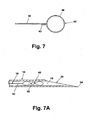
- Figs. 7 and 7A illustrate another shape for the localizing anchor 40, which has the shape of a ring 48 in the expanded condition.
- the anchor shapes illustrated in Figs. 3-7A are similar in that they are of a thread type structure that encloses an area. When the anchor 40 is in the expanded condition, the enclosed area is much greater than when in the collapsed condition. These shapes have no sharp edges that would penetrate the surrounding tissue, yet they still anchor the localizing wire. The lack of penetrating edges reduces the trauma to the patient during repositioning.
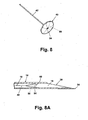
- Figs. 8 and 8A illustrate another localizing anchor 40 comprising a disc 54, preferably formed with regularly-spaced fold lines 56 for collapsing the disc 54, similar to an umbrella.
- a dual-lumen cannula 60 can be utilized comprising a primary lumen 62 and a secondary lumen 64.
- the primary lumen 62 carries the localizing wire 10
- the secondary lumen 64 can carry a conventional imaging marker 66 such as that disclosed in U.S. Patent No. 6,575,991 or can be used for the introduction of dye, irrigating fluid, pharmaceuticals, and the like.
- the localizing wire 10 is utilized as follows.
- the localizing wire 10 is first loaded into the lumen 16 for introduction of the cannula 14 into the tissue of interest 18.
- the cannula 14 is introduced into the tissue 18 so that the insertion tip 34 is at the location of interest, for example adjacent to or penetrating the lesion.
- the localizing wire 10 is then placed at the location of interest by relatively moving the localizing wire 10 and the cannula 14 to expose the anchor 40 beyond the cannula 14. The relative movement is traditionally accomplished by advancing the localizing wire 10 relative to the cannula 14.
- the cannula can be retracted relative to the localizing wire 10 as disclosed in U.S. Patent Application No. 10/707,043, filed November 17, 2003 , entitled Apparatus And Method For Implanting A Preloaded Localization Wire (Publ. no US 2004/122 312 ).
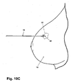
- the localizing anchor 40 As the localizing anchor 40 exits the end of the cannula, it expands from the collapsed to the expanded condition. As it expands into the surrounding tissue, the anchor 40 compresses and/or displaces the adjacent tissue sufficiently to imbed the localizing anchor 40 in the tissue at the location of interest, but does not puncture the tissue as with a hook-type anchor. If the localizing anchor 40 is not satisfactorily placed at the selected location, the localizing wire 10 can be retracted into the lumen 16 as shown in Fig. 10C by pulling on the localizing thread 42 and drawing the anchor 40 back into the cannula. As the anchor 40 contacts the cannula 12, the interference between the cannula 12 and the anchor collapses the anchor 40 from the expanded to the collapsed condition.
- the cannula 14 can then be repositioned and the localizing wire 10 ejected from the lumen 16 into the new location.
- the cannula 14 can then be removed from the tissue 18, leaving the localizing wire 10 in place with the localizing anchor 40 at the location of interest, and the localizing thread 42 extending outside the tissue 18 as with a conventional localizing wire.
- Removal of the localizing wire 10 can be accomplished by passing the cannula 14 over the localizing thread 42 and inserting the cannula 14 into the tissue 18 to the localizing anchor 40.
- the localizing anchor 40 can then be retracted into the lumen 16, followed by removal of the cannula 14 from the tissue 18.
- the localizing anchor 40 can be repositioned as discussed above.
- the localizing wire 10 can also be removed without the reintroduction of the cannula 14 by merely pulling the localizing thread 42 away from the tissue 18.
- the localizing anchor 40 will be urged into a collapsed configuration by the tissue 18 to facilitate removal of the localizing anchor 40 from the tissue 18.
- Prior localizing wires using a hook-shaped anchor that pierced the tissue could not be removed from the tissue without causing substantial tissue trauma unless a cannula was used.
- the localizing wire 10 can be removed without a cannula with a sufficient force, but will not cause the same trauma to the surrounding tissue as the prior art devices since the anchor 40 does not rely on piercing the tissue for anchoring.
- the localizing wire described herein has the advantage of being readily repositionable through retraction of the localizing wire into the lumen of a cannula after the localizing wire has been expelled from the lumen. Unlike prior art localizing wires having a hook-like configuration, the localizing wire does not puncture the tissue, whereas the prior art localizing wires puncture the tissue, complicating, if not precluding, removal of the localizing wire from the tissue. Furthermore, the localizing wire described herein can be removed from the tissue without the necessity of reinserting a cannula into the tissue, thereby minimizing injury and discomfort to the patient.
- the anchors not to completely bound an area.
- the end 43 need not be attached to the thread 42. Instead, the end 43 could be unattached and be shaped to follow the leg 47 or ring 48. The end 43 could even be excluded and the leg 47 or ring 48 could just terminate prior to the thread 42. In either of these configurations, the area would be effectively bounded, not actually bounded and the bound area would be an effectively bound area.
- the term area as used in this application includes both an actually bound area and an effectively bound area.
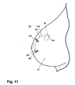
- Fig. 11 illustrates an alternative embodiment localizing wire 110 comprising an anchor 140 and thread 142, with at least the thread 142 being configured such that the exterior portion 143 of the thread 142 will lie substantially flat against the exterior of the tissue 18.
- the ability of the thread 142 to lie against and not project substantially above the tissue 18 significantly reduces the likelihood that the thread 142 will be accidentally caught or hooked on a person, machine or other object. This significantly reduces the likelihood that the anchor 140 will be dislodged from the position selected by the medical professional. If the anchor 140 was moved from its initial position, it would reduce the efficacy of the wire 110 in marking the biopsy site or lesion.
- the ability of the thread 142 to lie substantially flat against the tissue 18 also reduces the likelihood of trauma to the tissue 18 caused by the jerking of the wire 110.
- Tape 146 or another similar material can be used to hold the thread 142 in place against the exterior of the tissue 18.
- the second moment of area, I is a physical property of the wire. It is representative of the distribution of the mass of the object relative to the objects geometric axis. The greater the mass is distributed from the geometric axis, the greater the value of I , and the more resistant the object is to bending about the geometric axis.
- the Young's Modulus essentially defines the stiffness of the material. All things being equal, the greater the Young's Modulus of a material, the greater the material will resist deflection.
- the Young's Modulus provides more room for adjustment to get the wire to lay flat against the tissue mass. This is because the cross-sectional area of the localizing wire has become somewhat standardized along with the cannula. Thus, the Young's Modulus is the best candidate for ensuring that the external portion of the localizing wire will lie substantially flat against the tissue.
- the second moment of area and the Young's Modulus are selected such that the exterior portion of the localizing wire can be bent over and held against the tissue mass by a suitable fastener, such as tape.
- the second moment of area and the Young's Modulus are selected such that the bending does not result in plastic deformation of the localizing wire as such deformation is more likely to cause the portion of the localizing wire within the tissue mass to move, which might negate the marking functionality of the localizing wire.
- the second moment of area and the Young's Modulus are selected such that the external portion of the localizing wire bends as needed under its own weight.
- the bending occur immediately at or around the insertion point 145 of the localizing wire into the tissue mass, it is not necessary. If the localizing wire does not bend near the insertion point 145 before the localizing wire lies flat against the tissue, a gap will form between the localizing wire and the tissue thereby effectively creating a small loop on which something could catch. The smaller this loop, the less likely an object will catch it. Thus, this loop should be minimized, but it should be done is such a way that does not cause the shifting of the internal portion of the localizing wire, which would negate the marking functionality.
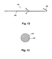
- Figs. 12 and 13 illustrate a localizing wire 210 configured to lie flat against the exterior of the tissue mass and comprising a straight thread 242 and a hook-shaped anchor 240.
- the thread has a generally circular cross section 244.
- Other cross sections can be used, such as oval, square, polygonal, and they can be either hollow or solid.
- the circular cross section 244 as illustrated is typical of current localizing wires that do not have the lie flat functionality.
- the localizing wire is made from a material that provides a Young's Modulus that when combined with the cross section will permit the thread 242 to lie flat against the tissue 18.
- a suitable material is annealed steel. The annealing of the steel reduces the stiffness of the material, which reduces the Young's Modulus, to permit the bending of the thread 242 as needed to lie flat.
- localizing wire 242 bends as needed to lie flat under its own weight.
- the portion of the thread 242 extending exteriorly of the tissue preferably has sufficient mass to effect the bending.
- the length of the thread preferably takes into account a suitable safety margin to ensure that there is enough thread 242 exterior of the tissue mass to effect the bending.
- the entire length of the thread need be configured to effect the lying flat of the thread on the exterior of the tissue mass.
- This portion of the thread can be referred to as the bending portion, which may extend along all or only a portion of the thread. It is anticipated that only that portion of the thread generally near the insertion point 145 into the tissue mass need be so configured if the bending is to minimize any gap between the exterior of the tissue and the thread. However, it is anticipated that for manufacturing simplicity, the entire thread will be so configured, especially if the material is treated to select the desired Young's Modulus.
- Figs. 14-16 illustrate another embodiment of a localizing wire 310 that can be repositioned like the localizing wire 10. Additionally, the localizing wire 310 can be withdrawn from the tissue mass 18 after the localizing wire 310 is implanted and after the removal of the cannula 14, without the reintroduction of the cannula 14.
- the localizing wire 310 comprises a configurable anchor 340 and a thread 342.
- An actuator for reconfiguring the configurable anchor in the form of a sheath 350 is slidably mounted on the thread 342.
- the anchor 340 is made of a resilient material, such as Nitinol, that permits the anchor 340 to be configured between an anchoring configuration ( Fig. 13 ), where it has a hook-like shape for anchoring in the tissue mass, and a release configuration (shown in phantom in Fig. 14 ), where the anchor is generally straight relative to the thread 342 to release the anchor 340 from the tissue mass 18.
- the sheath 350 has a proximal end 352 near the anchor 340 and an opposing distal end 354.
- the sheath 350 defines a hollow interior 356 in which the thread 342 is received to slidably couple the sheath 350 and thread 342 for relative slidable movement.
- the sheath 350 functions as an actuator for moving the anchor between the anchoring and release configurations.
- the sheath 350 is withdrawn from the anchor 340 ( Fig. 14 )
- the anchor 340 because of its resiliency will inherently assume the anchoring configuration.
- the sheath 350 is advanced toward the anchor 340 by the relative movement of the thread 342 and sheath 350.
- the proximal end 352 of the sheath 350 As the proximal end 352 of the sheath 350 is advanced toward the anchor 340, the proximal end 352 comes into contact with the anchor 340. The continued advancement of the sheath 350 causes the anchor 340 to straighten as it is received within the interior 356 of the sheath 350 and thereby effect the reconfiguring of the anchor 340 into the release configuration.
- the anchor 340 need not be completely received within the interior 356 of the sheath 350 for the anchor 340 to be in the release configuration.
- the anchor 340 need only be straightened enough that the anchor will release from the tissue.
- the complete receipt of the anchor 340 in the interior 356 of the sheath 350 is preferred as that ensures that the anchor 340 is straight enough and it will cause the least amount of tissue damage when the localizing wire is moved or withdrawn.
- the sheath 350 is illustrated as being transparent, but it can have any desired degree of opacity.
- the sheath 350 is preferably made from a suitable plastic.
- the sheath 350 can also have any suitable type of imageable markings that permit the location of the sheath 350, especially the proximal end 352, which would permit the user to view the relative location of the proximal end 352 and the anchor 340, which can also have such imageable markings.
- imageable markings are well known in the art and vary on the type of imaging technique being used.
- the implanting of the localizing wire 310 is essentially identical to that described for the localizing wire 10.
- an introducer typically a cannula 14 is inserted into the tissue mass 18.
- the localizing wire is inserted through the lumen of the cannula and out the open end of the cannula, where the anchor 340 can anchor in the tissue mass 18. Once the localizing wire is properly positioned, the cannula 14 is withdrawn.
- the localizing wire 310 can be inserted along with the cannula 14 or after the cannula 14 is inserted.
- the localizing wire 310 can be inserted with the anchor 340 either in the anchoring configuration or the release configuration. If it is inserted in the release configuration, it will, of course, need to be put in the anchoring configuration to anchor.
- the localizing wire 310 can be repositioned or withdrawn without the need for reinserting the cannula 14, as is now required.
- the localizing wire 310 can be repositioned or withdrawn by relatively moving the thread 342 and sheath 350 such that the anchor is reconfigured from the anchoring configuration to the release configuration. In the release configuration, the localizing wire can be repositioned or withdrawn. If repositioned, the sheath 350 and thread 342 are relatively moved to configure the anchor in the anchoring configuration and re-anchor the localizing wire. If withdrawn, the user merely pulls on the exterior portion of the localizing wire 310.
- the reconfiguring of the anchor 340 after the implanting of the localizing wire 310 can be done by manipulating the portions of the sheath 350 and thread 342 (sliding them relative to each other) that extend exteriorly of the tissue mass. This prevents the need for reinserting the cannula 14 as is currently done.
- the ability to remove the localizing wire 310 without the reintroduction of the cannula 14 is very beneficial. Often the localizing wire 310 will be inserted in a tissue mass at the location of a biopsy site. The localizing wire 310 is left in while analysis is run on the biopsy specimen. It can take from a few hours to a few days to complete the analysis. This is too long of a time to leave the cannula 14 inserted in the patient as the rigid cannula 14 is uncomfortable, if not painful, when left in. It can also increase the risk of infection since the lumen of the cannula 14 creates an open air pathway into the tissue mass 18.
- the localizing wire can easily be removed without reintroducing the cannula 14, eliminating additional tissue damage and discomfort for the patient, not to mention the cost of the cannula insertion procedure.
- the cannula 14 need not be completely withdrawn from the tissue mass for the sheath 340 to be used to effect the reconfiguring of the anchor.
- the cannula 14 need only be withdrawn away from the anchor a sufficient amount such that the cannula 14 does not interfere with the reconfiguring of the anchor. It is expected that in most cases the cannula will be complete removed because of the increased risk of infection and accidental tissue damage if it is left in placed, especially since the cannula will no longer be needed for the removal of the localizing wire because of the sheath.
- the anchor could extend beyond the end of the sheath but would still be constrained in the release configuration by the cannula, and the withdrawal of the cannula away from the anchor would effect the reconfiguration of the anchor to the anchor configuration.
- the sheath could then be used to reconfigure the anchor from the anchor configuration to the release configuration when it is desired to remove the localizing wire.
- Fig. 17 illustrates an alternative localizing wire 410 having an alternative design for the sheath in the form of a coil spring 450.
- the coil spring 450 is wound such that it defines a hollow interior 456 for receiving the thread 342.
- the coil spring 450 has a proximal end 452 and a distal end 454. The operation of the localizing wire 410 with the coil spring 450 is identical to that previously described.
- the localizing wires 310 and 410 can be configured to lay flat against the exterior of the tissue mass 18 as previously described. With the localizing wires 310, 410, the characteristics of both the thread 342, 442 and the sheath 350, 450 must be taken into account to achieve the laying flat functionality.
Landscapes
- Health & Medical Sciences (AREA)
- Surgery (AREA)
- Life Sciences & Earth Sciences (AREA)
- Heart & Thoracic Surgery (AREA)
- Molecular Biology (AREA)
- Oral & Maxillofacial Surgery (AREA)
- Engineering & Computer Science (AREA)
- Biomedical Technology (AREA)
- Nuclear Medicine, Radiotherapy & Molecular Imaging (AREA)
- Medical Informatics (AREA)
- Pathology (AREA)
- Animal Behavior & Ethology (AREA)
- General Health & Medical Sciences (AREA)
- Public Health (AREA)
- Veterinary Medicine (AREA)
- Surgical Instruments (AREA)
- Suspension Of Electric Lines Or Cables (AREA)
Claims (12)
- Lokalisierungsdraht zur Markierung einer Läsionsstelle in einer Gewebemasse, wobei der Lokalisierungsdraht (10) zur Platzierung durch zumindest ein Kanülenlumen (16) relativ zu der Läsion ausgelegt ist, wobei der Lokalisierungsdraht (10) Folgendes umfasst:einen Lokalisierungsanker (40) zum Halten des Lokalisierungsdrahts (10) an einer ausgewählten Stelle in der Gewebemasse relativ zu der Läsion; undeinen Lokalisierungsfaden (42), der mit dem Lokalisierungsanker (40) verbunden ist und eine solche Größe aufweist, dass er sich außerhalb der Gewebemasse erstreckt, wenn der Lokalisierungsanker (40) an der ausgewählten Stelle gehalten wird;worin der Lokalisierungsanker (40) eine veränderbare Konfiguration aufweist, die zwischen einer Ankerkonfiguration, in welcher der Lokalisierungsdraht (10) an der Gewebemasse verankert wird, und einer Freigabekonfiguration, in welcher der Lokalisierungsdraht (10) aus der Gewebemasse zurückgezogen werden kann,verändert werden kann,worin der Lokalisierungsanker in Form eines nachgiebigen, physiologisch inerten Drahtstücks vorliegt,dadurch gekennzeichnet, dass der Lokalisierungsanker zur Bildung eines vollständig begrenzten Bereichs geformt ist, undworin der Lokalisierungsanker (40) eine kollabierte Gestalt aufweist, die einen ersten Bereich umreißt, wenn sich der Lokalisierungsanker (40) in der Freigabekonfiguration befindet, und eine ausgeweitete Gestalt aufweist, die einen zweiten Bereich, der größer als der erste Bereich ist, umreißt, wenn sich der Lokalisierungsanker (40) in der Ankerkonfiguration befindet.
- Lokalisierungsdraht nach Anspruch 1, worin der Lokalisierungsdraht (10) die kollabierte Gestalt annimmt, wenn er in dem zumindest einen Kanülenlumen (16) aufgenommen ist, und die ausgeweitete Gestalt aufweist, wenn er sich außerhalb des zumindest einen Kanülenlumens (16) befindet.
- Lokalisierungsdraht nach Anspruch 2, worin der Lokalisierungsanker (40) ausgelegt ist, in das zumindest eine Kanülenlumen (16) zurückgezogen zu werden, nachdem der Lokalisierungsanker (40) an der ausgewählten Stelle relativ zu der Läsion platziert wurde, indem die Gestalt des Ankers von der ausgeweiteten Gestalt in die kollabierte Gestalt geändert wird.
- Lokalisierungsdraht nach den Ansprüchen 1-3, worin die Gestalt des Lokalisierungsankers (40) durch Ziehen an dem Lokalisierungsfaden (42) von der ausgeweiteten Gestalt in die kollabierte Gestalt geändert werden kann.
- Lokalisierungsdraht nach den Ansprüchen 1-4, worin der Lokalisierungsanker (40) aus einem nachgiebigen Material gefertigt ist und sich inhärent aus der kollabierten Gestalt in die expandierte Gestalt ausweitet, um eine Kraft gegen die Gewebemasse aufzubringen.
- Lokalisierungsdraht nach einem der vorhergehenden Ansprüche, worin die ausgeweitete Gestalt des Lokalisierungsankers ein Vieleck, ein Quadrat, ein Kreis, ein Dreieck oder eine Scheibe ist.
- Lokalisierungsdraht nach einem der Ansprüche 1-5, worin der Lokalisierungsanker und der Lokalisierungsdraht ein durchgehender Körper sind.
- Lokalisierungsdraht nach einem der Ansprüche 1-5, worin der Lokalisierungsanker und der Lokalisierungsfaden getrennte Körper sind.
- Lokalisierungsdraht nach einem der vorhergehenden Ansprüche, worin der Lokalisierungsfaden eine solche Querschnittsfläche und einen solchen Young-Modul aufweist, dass ein äußerer Abschnitt des Fadens, der sich außerhalb der Gewebemasse erstreckt, so verformbar ist, dass er im Wesentlichen flach an der Außenseite der Gewebemasse anliegt.
- Lokalisierungsdraht nach Anspruch 9, worin der Lokalisierungsfaden einen Biegeabschnitt aufweist, so dass sich der Faden ohne plastische Verformung biegt und der äußere Abschnitt des Fadens so verformbar ist, dass er im Wesentlichen flach an der Außenseite der Gewebemasse anliegt.
- Lokalisierungsdraht nach Anspruch 9, worin der Lokalisierungsdraht ein zweites Flächenmoment definiert, wobei das zweite Flächenmoment in Kombination mit dem Young-Modul so ausgelegt ist, dass sich der Lokalisierungsfaden unter seinem eigenen Gewicht biegen kann, so dass der äußere Abschnitt des Fadens im Wesentlichen flach an der Außenseite der Gewebemasse anliegen kann.
- Lokalisierungsdraht nach einem der vorhergehenden Ansprüche, worin der Lokalisierungsfaden ein Draht ist.
Applications Claiming Priority (1)
| Application Number | Priority Date | Filing Date | Title |
|---|---|---|---|
| US10/904,666 US8409111B2 (en) | 2004-11-22 | 2004-11-22 | Removable localizing wire |
Publications (3)
| Publication Number | Publication Date |
|---|---|
| EP1658820A2 EP1658820A2 (de) | 2006-05-24 |
| EP1658820A3 EP1658820A3 (de) | 2006-07-12 |
| EP1658820B1 true EP1658820B1 (de) | 2015-03-18 |
Family
ID=35811577
Family Applications (1)
| Application Number | Title | Priority Date | Filing Date |
|---|---|---|---|
| EP05025263.4A Ceased EP1658820B1 (de) | 2004-11-22 | 2005-11-18 | Entfernbarer Lokalisierungsdraht |
Country Status (4)
| Country | Link |
|---|---|
| US (4) | US8409111B2 (de) |
| EP (1) | EP1658820B1 (de) |
| CN (1) | CN1806770B (de) |
| CA (2) | CA2527062C (de) |
Families Citing this family (42)
| Publication number | Priority date | Publication date | Assignee | Title |
|---|---|---|---|---|
| DE60330705D1 (de) | 2002-11-18 | 2010-02-04 | Bard Peripheral Vascular Inc | Gerät zum implantieren eines vorgespannten lokalisierungsdrahtes |
| US8409111B2 (en) | 2004-11-22 | 2013-04-02 | Bard Peripheral Vascular, Inc. | Removable localizing wire |
| ATE465673T1 (de) | 2005-02-08 | 2010-05-15 | Koninkl Philips Electronics Nv | System zur perkutanen glossoplastik |
| US10265100B2 (en) | 2010-10-27 | 2019-04-23 | Dtherapeutics, Llc | Transradial access devices, systems, and methods |
| US10219828B2 (en) * | 2010-10-27 | 2019-03-05 | Dtherapeutics, Llc | Devices, systems, and methods for transradial access |
| US9968337B2 (en) * | 2010-12-20 | 2018-05-15 | Cook Medical Technologies Llc | Coring tissue biopsy needle and method of use |
| US10278676B2 (en) * | 2012-06-27 | 2019-05-07 | Michael J. Vaillancourt | Safety shield for a needle assembly |
| US9161814B2 (en) | 2013-03-15 | 2015-10-20 | Covidien Lp | Microwave energy-delivery device and system |
| US9119650B2 (en) | 2013-03-15 | 2015-09-01 | Covidien Lp | Microwave energy-delivery device and system |
| US20140259681A1 (en) * | 2013-03-15 | 2014-09-18 | Equalizer Industries, Inc. | Apparatus for placing a sealant cutting wire through a bead of sealant in a glass installation |
| US9301723B2 (en) | 2013-03-15 | 2016-04-05 | Covidien Lp | Microwave energy-delivery device and system |
| US10624697B2 (en) | 2014-08-26 | 2020-04-21 | Covidien Lp | Microwave ablation system |
| US10376674B2 (en) | 2014-09-15 | 2019-08-13 | Ethicon, Inc. | System and method for targeted delivery of therapeutic agents to tissue |
| CN107072693B (zh) * | 2014-09-15 | 2021-03-12 | 伊西康公司 | 用于将治疗剂定向递送至组织的系统 |
| CN104490480A (zh) * | 2015-01-14 | 2015-04-08 | 浙江伽奈维医疗科技有限公司 | 一种菱形的定位导丝及定位针 |
| JP7082052B2 (ja) | 2015-09-03 | 2022-06-07 | ネプチューン メディカル インク. | 小腸内での内視鏡前進の為の器具 |
| EP3367936B1 (de) * | 2015-10-26 | 2023-09-06 | Smiths Medical International Limited | Echogene nadelanordnungen |
| US10813692B2 (en) | 2016-02-29 | 2020-10-27 | Covidien Lp | 90-degree interlocking geometry for introducer for facilitating deployment of microwave radiating catheter |
| WO2019232354A1 (en) | 2018-05-31 | 2019-12-05 | Neptune Medical Inc. | Device and method for enhanced visualization of the small intestine |
| EP3500151A4 (de) | 2016-08-18 | 2020-03-25 | Neptune Medical Inc. | Vorrichtung und verfahren zur verbesserten visualisierung des dünndarms |
| WO2019018682A1 (en) | 2017-07-20 | 2019-01-24 | Neptune Medical Inc. | DYNAMICALLY RIGIDING SURFACE |
| US12403306B2 (en) | 2017-10-23 | 2025-09-02 | Cardiac Pacemakers, Inc. | Electric field shaping leads for treatment of cancer |
| US11338135B2 (en) | 2017-10-23 | 2022-05-24 | Cardiac Pacemakers, Inc. | Medical devices for cancer therapy with electric field shaping elements |
| EP3787520B1 (de) | 2018-05-04 | 2024-09-25 | Hologic, Inc. | Biopsienadelvisualisierung |
| US12121304B2 (en) * | 2018-05-04 | 2024-10-22 | Hologic, Inc. | Introducer and localization wire visualization |
| WO2020018934A1 (en) | 2018-07-19 | 2020-01-23 | Nep Tune Medical Inc. | Dynamically rigidizing composite medical structures |
| US11793392B2 (en) | 2019-04-17 | 2023-10-24 | Neptune Medical Inc. | External working channels |
| JP2022529936A (ja) | 2019-04-17 | 2022-06-27 | ネプチューン メディカル インク. | 医療用動的硬化複合構造 |
| EP4480526A3 (de) | 2019-04-22 | 2025-03-12 | Boston Scientific Scimed, Inc. | Elektrische und chemotherapeutische kombinationsbehandlung von krebs |
| US11691006B2 (en) | 2019-04-22 | 2023-07-04 | Boston Scientific Scimed, Inc. | Electrical stimulation devices for cancer treatment |
| CN113766949B (zh) | 2019-04-22 | 2025-04-08 | 波士顿科学国际有限公司 | 用于施用电刺激以治疗癌症的系统 |
| EP3958960B1 (de) | 2019-04-23 | 2025-06-18 | Boston Scientific Scimed, Inc. | Elektrische stimulation mit thermischer behandlung oder thermischer überwachung |
| JP2022529374A (ja) | 2019-04-23 | 2022-06-21 | ボストン サイエンティフィック サイムド,インコーポレイテッド | がん治療のための電気刺激用電極 |
| US11607542B2 (en) | 2019-04-23 | 2023-03-21 | Boston Scientific Scimed, Inc. | Electrical stimulation for cancer treatment with internal and external electrodes |
| CN115515674A (zh) | 2020-02-24 | 2022-12-23 | 波士顿科学国际有限公司 | 用于治疗胰腺癌的系统和方法 |
| AU2021245989A1 (en) | 2020-03-30 | 2022-10-27 | Neptune Medical Inc. | Layered walls for rigidizing devices |
| JP2024505529A (ja) | 2021-01-29 | 2024-02-06 | ネプチューン メディカル インク. | 動的に剛体化する装置の意図しない運動を防止するデバイスおよび方法 |
| CA3211622A1 (en) | 2021-03-10 | 2022-09-15 | Neal Tanner | Control of robotic dynamically rigidizing composite medical structures |
| CA3249667A1 (en) | 2022-04-19 | 2023-10-26 | Neptune Medical Inc. | MANAGEMENT AND HANDLING OF A LONG-LENGTH ROBOTIC ENDOSCOPE |
| CN119233783A (zh) | 2022-04-27 | 2024-12-31 | 海王星医疗公司 | 用于内窥镜检查的卫生护套 |
| AU2024338348A1 (en) | 2023-09-07 | 2026-03-19 | Neptune Medical Inc. | Pressure rigidization apparatuses and methods |
| AU2024353942A1 (en) | 2023-09-28 | 2026-03-19 | Neptune Medical Inc. | Telescoping robot |
Family Cites Families (115)
| Publication number | Priority date | Publication date | Assignee | Title |
|---|---|---|---|---|
| US36885A (en) * | 1862-11-11 | Improvement in osciluating steam-engines | ||
| US24332A (en) * | 1859-06-07 | Ftjenace and stove | ||
| US2876770A (en) * | 1955-10-10 | 1959-03-10 | Raymond A White | Shielded hypodermic syringe |
| GB786850A (en) | 1956-08-30 | 1957-11-27 | Foundation Lab Inc | An implanter and cartridge therefor |
| US2907327A (en) * | 1957-02-08 | 1959-10-06 | Pfizer & Co C | Pellet implanter |
| US3516412A (en) * | 1965-08-16 | 1970-06-23 | Electro Catheter Corp | Bipolar electrode having irregularity at inserting end thereof and method of insertion |
| US4007732A (en) * | 1975-09-02 | 1977-02-15 | Robert Carl Kvavle | Method for location and removal of soft tissue in human biopsy operations |
| US4103690A (en) * | 1977-03-21 | 1978-08-01 | Cordis Corporation | Self-suturing cardiac pacer lead |
| IT1206220B (it) * | 1981-09-30 | 1989-04-14 | Caselgrandi Ivo Palmieri Benia | Siringa particolarmente idonea per biopsie ad ago avente un dispositivo che permette la fase aspirante, generata dalla corsa a ritroso dello stantuffo automaticamente |
| US4582061A (en) * | 1981-11-18 | 1986-04-15 | Indianapolis Center For Advanced Research, Inc. | Needle with ultrasonically reflective displacement scale |
| US4405314A (en) * | 1982-04-19 | 1983-09-20 | Cook Incorporated | Apparatus and method for catheterization permitting use of a smaller gage needle |
| US5542915A (en) * | 1992-08-12 | 1996-08-06 | Vidamed, Inc. | Thermal mapping catheter with ultrasound probe |
| US4627420A (en) * | 1983-10-31 | 1986-12-09 | Katz Harry R | Needle inserting instrument for interstitial radiotherapy |
| US4799795A (en) * | 1984-03-19 | 1989-01-24 | D.O.M. Associates, Inc. | Stationary, electrically alterable, optical masking device and spectroscopic apparatus employing same |
| US4592356A (en) * | 1984-09-28 | 1986-06-03 | Pedro Gutierrez | Localizing device |
| US4616656A (en) * | 1985-03-19 | 1986-10-14 | Nicholson James E | Self-actuating breast lesion probe and method of using |
| US4634432A (en) * | 1985-05-13 | 1987-01-06 | Nuri Kocak | Introducer sheath assembly |
| US4669473A (en) * | 1985-09-06 | 1987-06-02 | Acufex Microsurgical, Inc. | Surgical fastener |
| US4799495A (en) | 1987-03-20 | 1989-01-24 | National Standard Company | Localization needle assembly |
| US4874376A (en) * | 1987-04-13 | 1989-10-17 | Hawkins Jr Irvin F | Needle guide assembly |
| US4747831A (en) * | 1987-04-29 | 1988-05-31 | Phase Medical, Inc. | Cannula insertion set with safety retracting needle |
| US4909250A (en) * | 1988-11-14 | 1990-03-20 | Smith Joseph R | Implant system for animal identification |
| US4986279A (en) * | 1989-03-01 | 1991-01-22 | National-Standard Company | Localization needle assembly with reinforced needle assembly |
| GB2230191B (en) * | 1989-04-15 | 1992-04-22 | Robert Graham Urie | Lesion location device |
| CA2015326A1 (en) | 1989-05-05 | 1990-11-06 | Frederick C. Houghton | Electrically insulated breast lesion localization device |
| NL8902186A (nl) | 1989-08-30 | 1991-03-18 | Nedap Nv | Herlaadbaar implanteergereedschap met automatische ontgrendeling. |
| US5353804A (en) * | 1990-09-18 | 1994-10-11 | Peb Biopsy Corporation | Method and device for percutaneous exisional breast biopsy |
| US5057114A (en) * | 1990-09-18 | 1991-10-15 | Cook Incorporated | Medical retrieval basket |
| US5282845A (en) * | 1990-10-01 | 1994-02-01 | Ventritex, Inc. | Multiple electrode deployable lead |
| US5221269A (en) | 1990-10-15 | 1993-06-22 | Cook Incorporated | Guide for localizing a nonpalpable breast lesion |
| US5176655A (en) | 1990-11-08 | 1993-01-05 | Mbo Laboratories, Inc. | Disposable medical needle and catheter placement assembly having full safety enclosure means |
| US5127916A (en) * | 1991-01-22 | 1992-07-07 | Medical Device Technologies, Inc. | Localization needle assembly |
| US5195540A (en) * | 1991-08-12 | 1993-03-23 | Samuel Shiber | Lesion marking process |
| NL9101489A (nl) * | 1991-09-03 | 1993-04-01 | Texas Instruments Holland | Injector voor het onderhuids implanteren van een voorwerp in een levend wezen. |
| US5976129A (en) * | 1991-10-18 | 1999-11-02 | Desai; Ashvin H. | Endoscopic surgical instrument |
| US5380290A (en) * | 1992-04-16 | 1995-01-10 | Pfizer Hospital Products Group, Inc. | Body access device |
| US5697907A (en) * | 1993-07-20 | 1997-12-16 | Graphic Controls Corporation | Safety catheter |
| US5376094A (en) * | 1993-08-19 | 1994-12-27 | Boston Scientific Corporation | Improved actuating handle with pulley system for providing mechanical advantage to a surgical working element |
| US5338311A (en) * | 1993-08-23 | 1994-08-16 | Mahurkar Sakharam D | Hypodermic needle assembly |
| US5836921A (en) * | 1993-08-23 | 1998-11-17 | Mahurkar; Sakharam D. | Hypodermic needle assembly |
| US5417708A (en) * | 1994-03-09 | 1995-05-23 | Cook Incorporated | Intravascular treatment system and percutaneous release mechanism therefor |
| DE4424394B4 (de) * | 1994-07-13 | 2004-12-16 | Bip Acquisition Company Inc., Wilmington | Vorrichtung zum Markieren von Gewebestellen |
| EP0781114B1 (de) * | 1994-09-16 | 2005-05-25 | Ethicon Endo-Surgery, Inc. | Vorrichtungen zum bestimmen und markieren von gewebe |
| US5954670A (en) * | 1994-10-05 | 1999-09-21 | Baker; Gary H. | Mandrel-guided tandem multiple channel biopsy guide device and method of use |
| US5795339A (en) * | 1995-03-07 | 1998-08-18 | Becton Dickinson And Company | Catheter-advancement actuated needle retraction system |
| CA2168615A1 (en) * | 1995-03-07 | 1996-09-08 | Timothy J. Erskine | Catheter-advancement actuated needle retraction system |
| FR2731343B1 (fr) * | 1995-03-08 | 1997-08-22 | De La Joliniere Jean H Bouquet | Dispositif de reperage de lesions suspectes du sein et appareil pour sa mise en place |
| US5782771A (en) | 1995-04-17 | 1998-07-21 | Hussman; Karl L. | Dual, fused, and grooved optical localization fibers |
| US6135993A (en) * | 1995-04-17 | 2000-10-24 | Hussman; Karl L. | Optical localization fiber |
| US5534007A (en) * | 1995-05-18 | 1996-07-09 | Scimed Life Systems, Inc. | Stent deployment catheter with collapsible sheath |
| US5800445A (en) * | 1995-10-20 | 1998-09-01 | United States Surgical Corporation | Tissue tagging device |
| CA2187975C (en) | 1995-10-20 | 2001-05-01 | Lisa W. Heaton | Surgical apparatus and method for marking tissue location |
| US6090063A (en) * | 1995-12-01 | 2000-07-18 | C. R. Bard, Inc. | Device, system and method for implantation of filaments and particles in the body |
| US6813520B2 (en) * | 1996-04-12 | 2004-11-02 | Novacept | Method for ablating and/or coagulating tissue using moisture transport |
| US5788710A (en) * | 1996-04-30 | 1998-08-04 | Boston Scientific Corporation | Calculus removal |
| US5902310A (en) * | 1996-08-12 | 1999-05-11 | Ethicon Endo-Surgery, Inc. | Apparatus and method for marking tissue |
| US5897554A (en) * | 1997-03-01 | 1999-04-27 | Irvine Biomedical, Inc. | Steerable catheter having a loop electrode |
| US6340367B1 (en) * | 1997-08-01 | 2002-01-22 | Boston Scientific Scimed, Inc. | Radiopaque markers and methods of using the same |
| EP1003422B1 (de) | 1997-08-05 | 2006-06-14 | Boston Scientific Limited | Ablösbares system zum verschliessen eines aneurysmashalses |
| US7125397B2 (en) | 1997-08-20 | 2006-10-24 | B. Braun Melsungen Ag | Protective device for an injection needle |
| US6080113A (en) * | 1998-09-11 | 2000-06-27 | Imagyn Medical Technologies California, Inc. | Incisional breast biopsy device |
| US6383145B1 (en) * | 1997-09-12 | 2002-05-07 | Imagyn Medical Technologies California, Inc. | Incisional breast biopsy device |
| US6551253B2 (en) * | 1997-09-12 | 2003-04-22 | Imagyn Medical Technologies | Incisional breast biopsy device |
| US6175760B1 (en) * | 1998-02-17 | 2001-01-16 | University Of Iowa Research Foundation | Lesion localizer for nuclear medicine |
| DE19807233A1 (de) | 1998-02-20 | 1999-08-26 | Acritec Gmbh | Vorrichtung zum Implantieren einer Intraocularlinse |
| US6540693B2 (en) * | 1998-03-03 | 2003-04-01 | Senorx, Inc. | Methods and apparatus for securing medical instruments to desired locations in a patients body |
| US6053925A (en) * | 1998-02-27 | 2000-04-25 | Barnhart; William H. | Lesion localization device and method |
| US6312429B1 (en) * | 1998-09-01 | 2001-11-06 | Senorx, Inc. | Electrosurgical lesion location device |
| US6638234B2 (en) * | 1998-03-03 | 2003-10-28 | Senorx, Inc. | Sentinel node location and biopsy |
| FR2776165B1 (fr) | 1998-03-18 | 2000-06-02 | Ordicam | Dispositif d'implantation de puce transpondeur d'identification pour animaux |
| WO1999051143A1 (en) * | 1998-04-07 | 1999-10-14 | Windy Hill Technology, Inc. | Methods and devices for the localization of lesions in solid tissue |
| US6161034A (en) * | 1999-02-02 | 2000-12-12 | Senorx, Inc. | Methods and chemical preparations for time-limited marking of biopsy sites |
| US6347241B2 (en) * | 1999-02-02 | 2002-02-12 | Senorx, Inc. | Ultrasonic and x-ray detectable biopsy site marker and apparatus for applying it |
| US6261302B1 (en) * | 1998-06-26 | 2001-07-17 | Ethicon Endo-Surgery, Inc. | Applier for implantable surgical marker |
| US6547762B1 (en) * | 1999-05-13 | 2003-04-15 | Mdc Investment Holdings, Inc. | Retractable needle medical device |
| US6179860B1 (en) * | 1998-08-19 | 2001-01-30 | Artemis Medical, Inc. | Target tissue localization device and method |
| US6679851B2 (en) * | 1998-09-01 | 2004-01-20 | Senorx, Inc. | Tissue accessing and anchoring device and method |
| US6936014B2 (en) * | 2002-10-16 | 2005-08-30 | Rubicor Medical, Inc. | Devices and methods for performing procedures on a breast |
| US6656192B2 (en) * | 1998-09-25 | 2003-12-02 | United States Surgical Corporatioin | Site marker device |
| US6241665B1 (en) * | 1998-10-21 | 2001-06-05 | Plc Medical System, Inc. | Percutaneous mapping system |
| US6951564B2 (en) | 1998-10-23 | 2005-10-04 | United States Surgical Corporation | Site marker device |
| DE69940475D1 (de) | 1998-10-23 | 2009-04-09 | United States Surgical Corp | Vorrichtung zum markieren von orten |
| WO2000024332A1 (en) | 1998-10-23 | 2000-05-04 | Cortese Armand F | Marker for indicating the location of identified tissue |
| US6156013A (en) * | 1998-11-04 | 2000-12-05 | Mahurkar; Sakharam D. | Safety syringe |
| US6371904B1 (en) * | 1998-12-24 | 2002-04-16 | Vivant Medical, Inc. | Subcutaneous cavity marking device and method |
| US6356782B1 (en) | 1998-12-24 | 2002-03-12 | Vivant Medical, Inc. | Subcutaneous cavity marking device and method |
| US6482178B1 (en) * | 1999-05-21 | 2002-11-19 | Cook Urological Incorporated | Localization device with anchoring barbs |
| US6066122A (en) * | 1999-06-09 | 2000-05-23 | Fisher; John | Needle apparatus and method for marking lesions |
| US6766186B1 (en) | 1999-06-16 | 2004-07-20 | C. R. Bard, Inc. | Post biospy tissue marker and method of use |
| US6575991B1 (en) * | 1999-06-17 | 2003-06-10 | Inrad, Inc. | Apparatus for the percutaneous marking of a lesion |
| US6364895B1 (en) * | 1999-10-07 | 2002-04-02 | Prodesco, Inc. | Intraluminal filter |
| US6685666B1 (en) * | 1999-11-12 | 2004-02-03 | Mark G. Fontenot | Catheters for breast surgery |
| US6564806B1 (en) * | 2000-02-18 | 2003-05-20 | Thomas J. Fogarty | Device for accurately marking tissue |
| AU2001238382A1 (en) * | 2000-02-18 | 2001-08-27 | Thomas J. M. D. Fogarty | Improved device for accurately marking tissue |
| AU2001273133A1 (en) * | 2000-08-10 | 2002-02-25 | Cook Incorporated | Localizer needle |
| EP1341435A4 (de) * | 2000-11-07 | 2005-08-17 | Artemis Medical Inc | Gewebetrennanordnung und -verfahren |
| US20020077687A1 (en) * | 2000-12-14 | 2002-06-20 | Ahn Samuel S. | Catheter assembly for treating ischemic tissue |
| US6824527B2 (en) | 2001-06-07 | 2004-11-30 | Peter Gollobin | Protective sheath for winged needles and sheath and needle assembly |
| US6755854B2 (en) * | 2001-07-31 | 2004-06-29 | Advanced Cardiovascular Systems, Inc. | Control device and mechanism for deploying a self-expanding medical device |
| JP4166691B2 (ja) | 2001-08-03 | 2008-10-15 | タイコ ヘルスケア グループ エルピー | 組織マーキング装置および方法 |
| AU2002301586B2 (en) | 2001-10-24 | 2009-12-10 | Becton, Dickinson And Company | Retractable needle apparatus |
| US20040030294A1 (en) | 2001-11-28 | 2004-02-12 | Mahurkar Sakharam D. | Retractable needle single use safety syringe |
| WO2003077730A2 (en) * | 2002-03-11 | 2003-09-25 | Wardle John L | Surgical coils and methods of deploying |
| US6776186B2 (en) * | 2002-06-07 | 2004-08-17 | Machine Design Specialists, Inc. | Dispensing tool for evacuating and charging a fluid system |
| WO2004020024A1 (en) * | 2002-08-30 | 2004-03-11 | Inrad, Inc. | Localizing needle with fluid delivery |
| US20040045444A1 (en) * | 2002-09-09 | 2004-03-11 | Mann Gary A. | Corn popper hopper apparatus |
| US8027712B2 (en) * | 2002-10-11 | 2011-09-27 | Ion Beam Applications S.A. | Elongated markers for soft tissue volume identification |
| WO2004045444A2 (en) | 2002-11-18 | 2004-06-03 | Inrad, Inc. | Tissue localizing and marking device and method of using same |
| DE60330705D1 (de) * | 2002-11-18 | 2010-02-04 | Bard Peripheral Vascular Inc | Gerät zum implantieren eines vorgespannten lokalisierungsdrahtes |
| WO2004050161A1 (en) * | 2002-12-02 | 2004-06-17 | Wilson-Cook Medical Inc. | Loop tip wire guide |
| US7247160B2 (en) * | 2002-12-30 | 2007-07-24 | Calypso Medical Technologies, Inc. | Apparatuses and methods for percutaneously implanting objects in patients |
| US7001341B2 (en) | 2003-08-13 | 2006-02-21 | Scimed Life Systems, Inc. | Marking biopsy sites |
| US20080097199A1 (en) | 2004-08-20 | 2008-04-24 | David Mullen | Tissue Marking Devices and Systems |
| US8409111B2 (en) | 2004-11-22 | 2013-04-02 | Bard Peripheral Vascular, Inc. | Removable localizing wire |
| US7945307B2 (en) | 2006-08-04 | 2011-05-17 | Senorx, Inc. | Marker delivery system with obturator |
-
2004
- 2004-11-22 US US10/904,666 patent/US8409111B2/en active Active
-
2005
- 2005-11-14 CA CA2527062A patent/CA2527062C/en not_active Expired - Lifetime
- 2005-11-14 CA CA2870406A patent/CA2870406C/en not_active Expired - Lifetime
- 2005-11-18 EP EP05025263.4A patent/EP1658820B1/de not_active Ceased
- 2005-11-22 CN CN2005101191933A patent/CN1806770B/zh not_active Expired - Fee Related
-
2006
- 2006-09-25 US US11/534,805 patent/US8287463B2/en not_active Expired - Fee Related
- 2006-09-25 US US11/534,798 patent/US8170648B2/en active Active
-
2012
- 2012-03-27 US US13/431,435 patent/US8744554B2/en not_active Expired - Lifetime
Also Published As
| Publication number | Publication date |
|---|---|
| US8287463B2 (en) | 2012-10-16 |
| US20060111629A1 (en) | 2006-05-25 |
| US20120239087A1 (en) | 2012-09-20 |
| CA2527062C (en) | 2015-02-03 |
| CN1806770A (zh) | 2006-07-26 |
| EP1658820A3 (de) | 2006-07-12 |
| US8744554B2 (en) | 2014-06-03 |
| CN1806770B (zh) | 2011-01-12 |
| US8170648B2 (en) | 2012-05-01 |
| CA2870406C (en) | 2017-03-14 |
| CA2870406A1 (en) | 2006-05-22 |
| US20070021763A1 (en) | 2007-01-25 |
| EP1658820A2 (de) | 2006-05-24 |
| US8409111B2 (en) | 2013-04-02 |
| CA2527062A1 (en) | 2006-05-22 |
| US20070021764A1 (en) | 2007-01-25 |
Similar Documents
| Publication | Publication Date | Title |
|---|---|---|
| US8744554B2 (en) | Removable localizing wire | |
| US6181960B1 (en) | Biopsy marker device | |
| US5853366A (en) | Marker element for interstitial treatment and localizing device and method using same | |
| US5415630A (en) | Method for removably implanting a blood filter in a vein of the human body | |
| JP7812406B2 (ja) | 組織を後退させる為の装置および方法 | |
| US7717930B2 (en) | Valvulotome with a cutting edge | |
| US7150712B2 (en) | Target tissue localization assembly and method | |
| EP0385604B1 (de) | Chirurgische Nadel und Nadelsatz zum Zwecke der Lokalisierung | |
| US6080178A (en) | Vena cava filter | |
| US8128641B2 (en) | Surgical coils and methods of deploying | |
| EP2895059B1 (de) | Abgabesystem | |
| EP1767167B1 (de) | System zum Einsetzen eines Markers nach Druckentlastung | |
| WO1998001068A9 (en) | Marker element for interstitial treatment and localizing device and method using same | |
| EP2002857A1 (de) | Haltemuffe mit Manschette zur Einführung in subkutane Regionen | |
| US20130226026A1 (en) | Pulmonary nodule access devices and methods of using the same | |
| CA2052999A1 (en) | Guide for localizing a nonpalpable breast lesion | |
| US8398663B2 (en) | Valvulotome device and method | |
| TW202304391A (zh) | 使用機械釋放臂在冠狀竇中固定導引線輸送導管 | |
| EP1567106B1 (de) | Gerät zum implantieren eines vorgespannten lokalisierungsdrahtes | |
| WO2012158188A2 (en) | Positioning cage | |
| EP4371502A2 (de) | Gefässlokalisierungsvorrichtung und verfahren zur lokalisierung eines gefässes | |
| WO2018144971A1 (en) | Implantable medical device system and methods of use | |
| US20240173030A1 (en) | Anchor devices, systems, and methods for non-adherent anatomical structures | |
| EP4599777A1 (de) | Prostatisches harnröhrenimplantat zur behandlung von prostatavergrösserung | |
| CN120899344A (zh) | 一种肺结节穿刺定位系统及定位方法 |
Legal Events
| Date | Code | Title | Description |
|---|---|---|---|
| PUAI | Public reference made under article 153(3) epc to a published international application that has entered the european phase |
Free format text: ORIGINAL CODE: 0009012 |
|
| AK | Designated contracting states |
Kind code of ref document: A2 Designated state(s): AT BE BG CH CY CZ DE DK EE ES FI FR GB GR HU IE IS IT LI LT LU LV MC NL PL PT RO SE SI SK TR |
|
| AX | Request for extension of the european patent |
Extension state: AL BA HR MK YU |
|
| PUAL | Search report despatched |
Free format text: ORIGINAL CODE: 0009013 |
|
| AK | Designated contracting states |
Kind code of ref document: A3 Designated state(s): AT BE BG CH CY CZ DE DK EE ES FI FR GB GR HU IE IS IT LI LT LU LV MC NL PL PT RO SE SI SK TR |
|
| AX | Request for extension of the european patent |
Extension state: AL BA HR MK YU |
|
| 17P | Request for examination filed |
Effective date: 20070108 |
|
| 17Q | First examination report despatched |
Effective date: 20070213 |
|
| AKX | Designation fees paid |
Designated state(s): DE FR GB IT |
|
| RAP1 | Party data changed (applicant data changed or rights of an application transferred) |
Owner name: BARD PERIPHERAL VASCULAR, INC. |
|
| GRAP | Despatch of communication of intention to grant a patent |
Free format text: ORIGINAL CODE: EPIDOSNIGR1 |
|
| INTG | Intention to grant announced |
Effective date: 20140915 |
|
| GRAP | Despatch of communication of intention to grant a patent |
Free format text: ORIGINAL CODE: EPIDOSNIGR1 |
|
| INTG | Intention to grant announced |
Effective date: 20141027 |
|
| GRAS | Grant fee paid |
Free format text: ORIGINAL CODE: EPIDOSNIGR3 |
|
| GRAA | (expected) grant |
Free format text: ORIGINAL CODE: 0009210 |
|
| AK | Designated contracting states |
Kind code of ref document: B1 Designated state(s): DE FR GB IT |
|
| REG | Reference to a national code |
Ref country code: GB Ref legal event code: FG4D |
|
| REG | Reference to a national code |
Ref country code: DE Ref legal event code: R096 Ref document number: 602005046063 Country of ref document: DE Effective date: 20150423 |
|
| REG | Reference to a national code |
Ref country code: FR Ref legal event code: PLFP Year of fee payment: 11 |
|
| REG | Reference to a national code |
Ref country code: DE Ref legal event code: R097 Ref document number: 602005046063 Country of ref document: DE |
|
| PLBE | No opposition filed within time limit |
Free format text: ORIGINAL CODE: 0009261 |
|
| STAA | Information on the status of an ep patent application or granted ep patent |
Free format text: STATUS: NO OPPOSITION FILED WITHIN TIME LIMIT |
|
| 26N | No opposition filed |
Effective date: 20151221 |
|
| REG | Reference to a national code |
Ref country code: FR Ref legal event code: PLFP Year of fee payment: 12 |
|
| REG | Reference to a national code |
Ref country code: FR Ref legal event code: PLFP Year of fee payment: 13 |
|
| REG | Reference to a national code |
Ref country code: FR Ref legal event code: PLFP Year of fee payment: 14 |
|
| PGFP | Annual fee paid to national office [announced via postgrant information from national office to epo] |
Ref country code: FR Payment date: 20221021 Year of fee payment: 18 |
|
| PGFP | Annual fee paid to national office [announced via postgrant information from national office to epo] |
Ref country code: IT Payment date: 20221020 Year of fee payment: 18 Ref country code: GB Payment date: 20221021 Year of fee payment: 18 |
|
| PGFP | Annual fee paid to national office [announced via postgrant information from national office to epo] |
Ref country code: DE Payment date: 20231019 Year of fee payment: 19 |
|
| GBPC | Gb: european patent ceased through non-payment of renewal fee |
Effective date: 20231118 |
|
| PG25 | Lapsed in a contracting state [announced via postgrant information from national office to epo] |
Ref country code: GB Free format text: LAPSE BECAUSE OF NON-PAYMENT OF DUE FEES Effective date: 20231118 |
|
| PG25 | Lapsed in a contracting state [announced via postgrant information from national office to epo] |
Ref country code: FR Free format text: LAPSE BECAUSE OF NON-PAYMENT OF DUE FEES Effective date: 20231130 |
|
| PG25 | Lapsed in a contracting state [announced via postgrant information from national office to epo] |
Ref country code: GB Free format text: LAPSE BECAUSE OF NON-PAYMENT OF DUE FEES Effective date: 20231118 Ref country code: FR Free format text: LAPSE BECAUSE OF NON-PAYMENT OF DUE FEES Effective date: 20231130 |
|
| PG25 | Lapsed in a contracting state [announced via postgrant information from national office to epo] |
Ref country code: IT Free format text: LAPSE BECAUSE OF NON-PAYMENT OF DUE FEES Effective date: 20231118 |
|
| PG25 | Lapsed in a contracting state [announced via postgrant information from national office to epo] |
Ref country code: IT Free format text: LAPSE BECAUSE OF NON-PAYMENT OF DUE FEES Effective date: 20231118 |
|
| REG | Reference to a national code |
Ref country code: DE Ref legal event code: R119 Ref document number: 602005046063 Country of ref document: DE |
|
| PG25 | Lapsed in a contracting state [announced via postgrant information from national office to epo] |
Ref country code: DE Free format text: LAPSE BECAUSE OF NON-PAYMENT OF DUE FEES Effective date: 20250603 |