EP1659009A2 - Mit einem Lager für einen Stabilisator integrierter Klemming - Google Patents
Mit einem Lager für einen Stabilisator integrierter Klemming Download PDFInfo
- Publication number
- EP1659009A2 EP1659009A2 EP05257124A EP05257124A EP1659009A2 EP 1659009 A2 EP1659009 A2 EP 1659009A2 EP 05257124 A EP05257124 A EP 05257124A EP 05257124 A EP05257124 A EP 05257124A EP 1659009 A2 EP1659009 A2 EP 1659009A2
- Authority
- EP
- European Patent Office
- Prior art keywords
- bushing
- stabilizer bar
- hole
- cords
- shell
- Prior art date
- Legal status (The legal status is an assumption and is not a legal conclusion. Google has not performed a legal analysis and makes no representation as to the accuracy of the status listed.)
- Withdrawn
Links
- 239000003381 stabilizer Substances 0.000 title claims abstract description 36
- 239000000725 suspension Substances 0.000 claims abstract description 7
- 238000000034 method Methods 0.000 claims description 6
- 230000002787 reinforcement Effects 0.000 claims description 3
- 238000000465 moulding Methods 0.000 claims 1
- 229910000831 Steel Inorganic materials 0.000 abstract description 3
- 239000010959 steel Substances 0.000 abstract description 3
- 239000002184 metal Substances 0.000 description 2
- 239000013536 elastomeric material Substances 0.000 description 1
- 239000000835 fiber Substances 0.000 description 1
- 239000000463 material Substances 0.000 description 1
- 238000012986 modification Methods 0.000 description 1
- 230000004048 modification Effects 0.000 description 1
- 239000012783 reinforcing fiber Substances 0.000 description 1
Images

Classifications
-
- B—PERFORMING OPERATIONS; TRANSPORTING
- B60—VEHICLES IN GENERAL
- B60G—VEHICLE SUSPENSION ARRANGEMENTS
- B60G21/00—Interconnection systems for two or more resiliently-suspended wheels, e.g. for stabilising a vehicle body with respect to acceleration, deceleration or centrifugal forces
- B60G21/02—Interconnection systems for two or more resiliently-suspended wheels, e.g. for stabilising a vehicle body with respect to acceleration, deceleration or centrifugal forces permanently interconnected
- B60G21/04—Interconnection systems for two or more resiliently-suspended wheels, e.g. for stabilising a vehicle body with respect to acceleration, deceleration or centrifugal forces permanently interconnected mechanically
- B60G21/05—Interconnection systems for two or more resiliently-suspended wheels, e.g. for stabilising a vehicle body with respect to acceleration, deceleration or centrifugal forces permanently interconnected mechanically between wheels on the same axle but on different sides of the vehicle, i.e. the left and right wheel suspensions being interconnected
- B60G21/055—Stabiliser bars
- B60G21/0551—Mounting means therefor
-
- B—PERFORMING OPERATIONS; TRANSPORTING
- B60—VEHICLES IN GENERAL
- B60G—VEHICLE SUSPENSION ARRANGEMENTS
- B60G2204/00—Indexing codes related to suspensions per se or to auxiliary parts
- B60G2204/10—Mounting of suspension elements
- B60G2204/12—Mounting of springs or dampers
- B60G2204/122—Mounting of torsion springs
- B60G2204/1222—Middle mounts of stabiliser on vehicle body or chassis
-
- B—PERFORMING OPERATIONS; TRANSPORTING
- B60—VEHICLES IN GENERAL
- B60G—VEHICLE SUSPENSION ARRANGEMENTS
- B60G2204/00—Indexing codes related to suspensions per se or to auxiliary parts
- B60G2204/40—Auxiliary suspension parts; Adjustment of suspensions
- B60G2204/41—Elastic mounts, e.g. bushings
-
- B—PERFORMING OPERATIONS; TRANSPORTING
- B60—VEHICLES IN GENERAL
- B60G—VEHICLE SUSPENSION ARRANGEMENTS
- B60G2204/00—Indexing codes related to suspensions per se or to auxiliary parts
- B60G2204/40—Auxiliary suspension parts; Adjustment of suspensions
- B60G2204/44—Centering or positioning means
- B60G2204/4404—Retainers for holding a fixing element, e.g. bushing, nut, bolt etc., until it is tightly fixed in position
-
- B—PERFORMING OPERATIONS; TRANSPORTING
- B60—VEHICLES IN GENERAL
- B60G—VEHICLE SUSPENSION ARRANGEMENTS
- B60G2206/00—Indexing codes related to the manufacturing of suspensions: constructional features, the materials used, procedures or tools
- B60G2206/01—Constructional features of suspension elements, e.g. arms, dampers, springs
- B60G2206/70—Materials used in suspensions
- B60G2206/71—Light weight materials
- B60G2206/7101—Fiber-reinforced plastics [FRP]
-
- B—PERFORMING OPERATIONS; TRANSPORTING
- B60—VEHICLES IN GENERAL
- B60G—VEHICLE SUSPENSION ARRANGEMENTS
- B60G2206/00—Indexing codes related to the manufacturing of suspensions: constructional features, the materials used, procedures or tools
- B60G2206/01—Constructional features of suspension elements, e.g. arms, dampers, springs
- B60G2206/80—Manufacturing procedures
Definitions
- This invention relates to an integrated stabilizer bushing and strap for securing a stabilizer bar to a vehicle.
- Stabilizer bars are mounted on a vehicle frame between opposing lateral suspension components such as control arms.
- the stabilizer bar provides lateral stability to the vehicle during turning maneuvers.
- a center portion of the stabilizer bar is typically secured to a vehicle using a rubber bushing mounted on the stabilizer bar.
- the bushing is received in a generally U-shaped strap that is secured to the vehicle frame by fasteners.
- the bushing may have a cut in it that extends to a bushing hole for receiving the stabilizer bar, so that the bushing may be installed over the center portion of the stabilizer bar without having to slide the bushing to the center portion starting from the end of the bar. Once the bushing is installed onto the stabilizer bar, the strap is secured over the bushing.
- the strap axially constrains the bushing, however, occasionally the bushing will come out of the strap during vehicle operation. Therefore, it is desirable to provide a bushing and strap arrangement in which the bushing will not move relative to the strap. Moreover, it is desirable to provide a bushing and strap arrangement in which the bushing and strap may be installed simultaneously on the stabilizer bar. It is further desirable to provide a lighter strap to reduce the overall weight of the stabilizer bar assembly.
- the inventive bushing includes a body having a hole for receiving the stabilizer bar.
- a base of the body may include a cut so that the bushing can be spread apart to insert the stabilizer through the cut and into the hole.
- the bushing includes a shell extending around, and molded as a single unit with, the exterior of the body, in one example embodiment.
- the shell provides legs, which are used to secure the bushing to the vehicle frame.
- the shell can be made similar to the steel belting of a tire and include one or more layers of cords to provide structural integrity to the shell.
- the layers of cords can be arranged at angles relative to one another to provide increased lateral stability.
- the shell can be made in other manners to provide the reinforcing fibers.
- cords should be interpreted to broadly mean any type of reinforcement fiber.
- the present invention provides a bushing and strap arrangement in which the bushing will not move relative to the strap since the two typically separate components are integrated.
- FIG. 1 An inventive suspension assembly 10 is shown in Figure 1.
- a stabilizer bar 14 is secured to a vehicle frame 12 using an inventive bushing and strap 18. As illustrated two bushings and straps 18 are utilized. As is well known in the art, opposing ends 16 of the stabilizer bar 14 are secured to opposing suspension components on either side of the vehicle, such as left and right control arms.
- the inventive bushing and strap 18 integrates the two components to provide a lightweight assembly in which the bushing and strap cannot move relative to one another.
- the bushing 18 includes a body 26, which may be manufactured from an elastomeric material such as rubber.
- the body 26 has a hole 25 for supporting a portion of the stabilizer bar 14.
- a base of the body 26 may include a cut 27 so that the bushing 18 may be opened at the cut 27 to insert the stabilizer bar 14 into the hole 25.
- the cut 27 may be omitted ( Figure 2B) and the base may be reinforced in the manner discussed below relative to the shell 28.
- the bushing 18 includes a shell 28 on the exterior of the body 26.
- the shell 28 is a reinforced portion of the body 26 used to secure the bushing 18 to the vehicle frame 12, replacing the conventional, separate metal strap.
- the shell 28 provides legs 20 having apertures 32. In Figure 2B, the shell 28 also extends between the legs 20.
- Fasteners 22 are located within the apertures 32 to secure the bushing 18 to the vehicle frame 12. Washers 24 may be arranged between the fastener heads and the legs 20 so that the clamping load may be distributed over a larger portion of the legs 20. Otherwise, the head of the fastener 22 may pull through the aperture 32. Alternatively, a special fastener having an enlarged head may be used.
- the shell 28 is similar to a steel belted tire in that it contains one or more layers of cords 30 arranged in desired directions to provide stability to the inventive bushing 18.
- layers 30A and 30B are arranged at angles relative to one another to minimize deflection of the bushing 18 in the lateral direction. That is, the cords are not all arranged parallel.
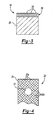
- the cords 30 are embedded in the elastomeric or rubber material making up the body 26 and shell 28, as shown in Figure 3, and may be metal or synthetic.
- the bushing 18 may be opened at the cut 27 and installed onto the stabilizer bar 14 as a single unit, which reduces costs associated with handling.
- the stabilizer bar 14 may then be installed onto the vehicle frame 12.
- the shell 28 is molded around the body 26, with the cords 30 being embedded by any appropriate technique. It may also be possible to mold the shell 28 and body 26 simultaneously.
Landscapes
- Engineering & Computer Science (AREA)
- Mechanical Engineering (AREA)
- Vehicle Body Suspensions (AREA)
Applications Claiming Priority (1)
| Application Number | Priority Date | Filing Date | Title |
|---|---|---|---|
| US10/992,162 US20060103100A1 (en) | 2004-11-18 | 2004-11-18 | Integrated stabilizer bar bushing and strap |
Publications (2)
| Publication Number | Publication Date |
|---|---|
| EP1659009A2 true EP1659009A2 (de) | 2006-05-24 |
| EP1659009A3 EP1659009A3 (de) | 2006-06-14 |
Family
ID=35566290
Family Applications (1)
| Application Number | Title | Priority Date | Filing Date |
|---|---|---|---|
| EP05257124A Withdrawn EP1659009A3 (de) | 2004-11-18 | 2005-11-18 | Mit einem Lager für Stabilisator integrierter Klemming |
Country Status (3)
| Country | Link |
|---|---|
| US (1) | US20060103100A1 (de) |
| EP (1) | EP1659009A3 (de) |
| BR (1) | BRPI0505307A (de) |
Cited By (3)
| Publication number | Priority date | Publication date | Assignee | Title |
|---|---|---|---|---|
| CN108501651A (zh) * | 2017-02-28 | 2018-09-07 | 住友理工株式会社 | 稳定器衬套 |
| CN111002779A (zh) * | 2019-12-19 | 2020-04-14 | 北京汽车集团越野车有限公司 | 一种稳定杆安装夹子 |
| FR3153865A1 (fr) * | 2023-10-09 | 2025-04-11 | Sogefi Suspensions | Palier pour barre stabilisatrice de véhicule |
Families Citing this family (3)
| Publication number | Priority date | Publication date | Assignee | Title |
|---|---|---|---|---|
| US20080106056A1 (en) * | 2006-11-07 | 2008-05-08 | Meritor Suspension Systems Company, U.S. | Heat shrunken low-friction stabilizer bar sleeve |
| JP5693012B2 (ja) * | 2010-01-20 | 2015-04-01 | 倉敷化工株式会社 | スタビライザブッシュ |
| US20250003464A1 (en) * | 2023-06-30 | 2025-01-02 | Rivian Ip Holdings, Llc | Isolation bushings with conforming multi-part covers |
Family Cites Families (18)
| Publication number | Priority date | Publication date | Assignee | Title |
|---|---|---|---|---|
| US1811923A (en) * | 1927-08-19 | 1931-06-30 | Flintermann Gerhard | Flexible support |
| USRE20887E (en) * | 1931-12-30 | 1938-10-18 | Jean merder | |
| BE537731A (de) * | 1952-11-19 | |||
| FR2122018A5 (de) * | 1971-01-14 | 1972-08-25 | Kleber Colombes | |
| US3892398A (en) * | 1972-06-14 | 1975-07-01 | Firestone Tire & Rubber Co | Compression spring |
| JPS5565615A (en) * | 1978-11-13 | 1980-05-17 | Bridgestone Corp | Pneumatic fender |
| US4778199A (en) * | 1986-05-05 | 1988-10-18 | The B. F. Goodrich Company | Suspension system |
| FR2603959B1 (fr) * | 1986-09-12 | 1992-07-24 | Intertechnique Sa | Dispositif amortisseur de chocs et de vibrations |
| JPS63184512A (ja) * | 1987-01-23 | 1988-07-30 | Tokai Rubber Ind Ltd | 車両用スタビライザ・ブツシユ |
| FR2643314B1 (fr) * | 1989-02-20 | 1991-05-10 | Caoutchouc Manuf Plastique | Procede de realisation de barres antidevers par collage in situ de paliers elastiques et barres antidevers realises selon ce procede |
| JP3047501B2 (ja) * | 1991-04-15 | 2000-05-29 | 豊田合成株式会社 | 筒状防振ブッシュ |
| FR2720692B1 (fr) * | 1994-06-02 | 1996-08-23 | Allevard Sa | Dispositif anti-dévers pour véhicule automobile et procédé de fabrication d'un tel dispositif. |
| DE19746357C1 (de) * | 1997-10-21 | 1999-05-12 | Vorwerk & Sohn | Gummi/Metall-Lager zur Anlenkung eines Stabilisators an einem Kraftfahrzeugaufbau |
| US6854750B2 (en) * | 2001-12-14 | 2005-02-15 | Meritor Light Vehicle Technology, Llc | Variable rate bushing for stabilizer bar |
| DE10164563C1 (de) * | 2001-12-14 | 2003-06-18 | Siemens Ag | Durchführung |
| US6889988B2 (en) * | 2002-04-17 | 2005-05-10 | Visteon Global Technologies, Inc. | Variable rate gripped bushing system |
| US6845994B2 (en) * | 2002-10-16 | 2005-01-25 | Visteon Global Technologies, Inc. | Gripped bushing system with alternating radial stiffness |
| US6845995B2 (en) * | 2002-11-08 | 2005-01-25 | Visteon Global Technologies, Inc. | Method of forming compression gripped bushing system |
-
2004
- 2004-11-18 US US10/992,162 patent/US20060103100A1/en not_active Abandoned
-
2005
- 2005-11-17 BR BRPI0505307-2A patent/BRPI0505307A/pt not_active IP Right Cessation
- 2005-11-18 EP EP05257124A patent/EP1659009A3/de not_active Withdrawn
Non-Patent Citations (1)
| Title |
|---|
| None |
Cited By (4)
| Publication number | Priority date | Publication date | Assignee | Title |
|---|---|---|---|---|
| CN108501651A (zh) * | 2017-02-28 | 2018-09-07 | 住友理工株式会社 | 稳定器衬套 |
| CN111002779A (zh) * | 2019-12-19 | 2020-04-14 | 北京汽车集团越野车有限公司 | 一种稳定杆安装夹子 |
| FR3153865A1 (fr) * | 2023-10-09 | 2025-04-11 | Sogefi Suspensions | Palier pour barre stabilisatrice de véhicule |
| WO2025078749A1 (fr) * | 2023-10-09 | 2025-04-17 | Sogefi Suspensions | Palier pour barre stabilisatrice de vehicule |
Also Published As
| Publication number | Publication date |
|---|---|
| US20060103100A1 (en) | 2006-05-18 |
| BRPI0505307A (pt) | 2006-07-18 |
| EP1659009A3 (de) | 2006-06-14 |
Similar Documents
| Publication | Publication Date | Title |
|---|---|---|
| US6991223B2 (en) | Composite leaf spring having an arcuate attachment arrangement for vehicle mounting | |
| EP1255056B1 (de) | Stabilisatorstab | |
| EP1897787B1 (de) | Karosserierahmenbauteil | |
| US6416114B1 (en) | Side impact beam | |
| CZ293903B6 (cs) | Kolo vozidla s podpěrným tělesem nouzového chodu | |
| US7017888B2 (en) | Attachment arrangement for a composite leaf spring which accommodates longitudinal movement through shear displacement | |
| US20160101660A1 (en) | Vehicle suspension member | |
| US20050211847A1 (en) | Variable-duct support assembly | |
| US7631947B2 (en) | Wheel including a rim, a hub, and a device for connecting the rim to the hub | |
| US20060103100A1 (en) | Integrated stabilizer bar bushing and strap | |
| US10919351B1 (en) | Loading bracket for composite structural components | |
| DE19530939C1 (de) | Fahrzeugrad mit wulstlosem Fahrzeugluftreifen | |
| US6460838B1 (en) | Fiber reinforced suspension member | |
| EP3456557B1 (de) | Schwenklenker einer kraftfahrzeugaufhängung | |
| US7419146B2 (en) | Composite leaf spring geometry with an interlocking interface | |
| US20070278828A1 (en) | Pillar for a Motor Vehicle | |
| US20150344119A1 (en) | Sliding connection between the floor structure and the hull structure of an aircraft | |
| US8419028B1 (en) | Suspension arm assembly and method retrofitting | |
| US8136864B2 (en) | Injection molded magnesium link and method of making an injection molded magnesium link | |
| EP4096992B1 (de) | Sattel für fahrzeuge wie fahrräder | |
| US8209842B2 (en) | Method of manufacturing a traction stud mount | |
| JP2003200900A (ja) | ブースタロケット結合装置及び方法 | |
| DE102016209689B4 (de) | Zweiteilige Radaufhängungseinheit | |
| JPS5952303B2 (ja) | Frp板ばね装置用目玉部材 | |
| JP3661404B2 (ja) | サスペンションアーム |
Legal Events
| Date | Code | Title | Description |
|---|---|---|---|
| PUAI | Public reference made under article 153(3) epc to a published international application that has entered the european phase |
Free format text: ORIGINAL CODE: 0009012 |
|
| PUAL | Search report despatched |
Free format text: ORIGINAL CODE: 0009013 |
|
| AK | Designated contracting states |
Kind code of ref document: A2 Designated state(s): AT BE BG CH CY CZ DE DK EE ES FI FR GB GR HU IE IS IT LI LT LU LV MC NL PL PT RO SE SI SK TR |
|
| AX | Request for extension of the european patent |
Extension state: AL BA HR MK YU |
|
| AK | Designated contracting states |
Kind code of ref document: A3 Designated state(s): AT BE BG CH CY CZ DE DK EE ES FI FR GB GR HU IE IS IT LI LT LU LV MC NL PL PT RO SE SI SK TR |
|
| AX | Request for extension of the european patent |
Extension state: AL BA HR MK YU |
|
| 17P | Request for examination filed |
Effective date: 20061127 |
|
| AKX | Designation fees paid |
Designated state(s): DE ES FR IT |
|
| 17Q | First examination report despatched |
Effective date: 20070221 |
|
| STAA | Information on the status of an ep patent application or granted ep patent |
Free format text: STATUS: THE APPLICATION IS DEEMED TO BE WITHDRAWN |
|
| 18D | Application deemed to be withdrawn |
Effective date: 20070704 |