EP1659018A1 - Vorrichtung und Verfahren zur Regelung der Geschwindigkeit eines Schienenfahrzeugs und solche Vorrichtung enthaltende Systeme - Google Patents
Vorrichtung und Verfahren zur Regelung der Geschwindigkeit eines Schienenfahrzeugs und solche Vorrichtung enthaltende Systeme Download PDFInfo
- Publication number
- EP1659018A1 EP1659018A1 EP05292408A EP05292408A EP1659018A1 EP 1659018 A1 EP1659018 A1 EP 1659018A1 EP 05292408 A EP05292408 A EP 05292408A EP 05292408 A EP05292408 A EP 05292408A EP 1659018 A1 EP1659018 A1 EP 1659018A1
- Authority
- EP
- European Patent Office
- Prior art keywords
- speed
- wheels
- pair
- curvature
- determining
- Prior art date
- Legal status (The legal status is an assumption and is not a legal conclusion. Google has not performed a legal analysis and makes no representation as to the accuracy of the status listed.)
- Granted
Links
Images



Classifications
-
- B—PERFORMING OPERATIONS; TRANSPORTING
- B61—RAILWAYS
- B61L—GUIDING RAILWAY TRAFFIC; ENSURING THE SAFETY OF RAILWAY TRAFFIC
- B61L25/00—Recording or indicating positions or identities of vehicles or trains or setting of track apparatus
- B61L25/02—Indicating or recording positions or identities of vehicles or trains
- B61L25/021—Measuring and recording of train speed
-
- B—PERFORMING OPERATIONS; TRANSPORTING
- B60—VEHICLES IN GENERAL
- B60L—PROPULSION OF ELECTRICALLY-PROPELLED VEHICLES; SUPPLYING ELECTRIC POWER FOR AUXILIARY EQUIPMENT OF ELECTRICALLY-PROPELLED VEHICLES; ELECTRODYNAMIC BRAKE SYSTEMS FOR VEHICLES IN GENERAL; MAGNETIC SUSPENSION OR LEVITATION FOR VEHICLES; MONITORING OPERATING VARIABLES OF ELECTRICALLY-PROPELLED VEHICLES; ELECTRIC SAFETY DEVICES FOR ELECTRICALLY-PROPELLED VEHICLES
- B60L3/00—Electric devices on electrically-propelled vehicles for safety purposes; Monitoring operating variables, e.g. speed, deceleration or energy consumption
- B60L3/08—Means for preventing excessive speed of the vehicle
-
- B—PERFORMING OPERATIONS; TRANSPORTING
- B61—RAILWAYS
- B61F—RAIL VEHICLE SUSPENSIONS, e.g. UNDERFRAMES, BOGIES OR ARRANGEMENTS OF WHEEL AXLES; RAIL VEHICLES FOR USE ON TRACKS OF DIFFERENT WIDTH; PREVENTING DERAILING OF RAIL VEHICLES; WHEEL GUARDS, OBSTRUCTION REMOVERS OR THE LIKE FOR RAIL VEHICLES
- B61F5/00—Constructional details of bogies; Connections between bogies and vehicle underframes; Arrangements or devices for adjusting or allowing self-adjustment of wheel axles or bogies when rounding curves
- B61F5/38—Arrangements or devices for adjusting or allowing self- adjustment of wheel axles or bogies when rounding curves, e.g. sliding axles, swinging axles
- B61F5/383—Adjustment controlled by non-mechanical devices, e.g. scanning trackside elements
-
- B—PERFORMING OPERATIONS; TRANSPORTING
- B60—VEHICLES IN GENERAL
- B60L—PROPULSION OF ELECTRICALLY-PROPELLED VEHICLES; SUPPLYING ELECTRIC POWER FOR AUXILIARY EQUIPMENT OF ELECTRICALLY-PROPELLED VEHICLES; ELECTRODYNAMIC BRAKE SYSTEMS FOR VEHICLES IN GENERAL; MAGNETIC SUSPENSION OR LEVITATION FOR VEHICLES; MONITORING OPERATING VARIABLES OF ELECTRICALLY-PROPELLED VEHICLES; ELECTRIC SAFETY DEVICES FOR ELECTRICALLY-PROPELLED VEHICLES
- B60L2200/00—Type of vehicles
- B60L2200/26—Rail vehicles
-
- B—PERFORMING OPERATIONS; TRANSPORTING
- B60—VEHICLES IN GENERAL
- B60L—PROPULSION OF ELECTRICALLY-PROPELLED VEHICLES; SUPPLYING ELECTRIC POWER FOR AUXILIARY EQUIPMENT OF ELECTRICALLY-PROPELLED VEHICLES; ELECTRODYNAMIC BRAKE SYSTEMS FOR VEHICLES IN GENERAL; MAGNETIC SUSPENSION OR LEVITATION FOR VEHICLES; MONITORING OPERATING VARIABLES OF ELECTRICALLY-PROPELLED VEHICLES; ELECTRIC SAFETY DEVICES FOR ELECTRICALLY-PROPELLED VEHICLES
- B60L2240/00—Control parameters of input or output; Target parameters
- B60L2240/10—Vehicle control parameters
- B60L2240/12—Speed
-
- Y—GENERAL TAGGING OF NEW TECHNOLOGICAL DEVELOPMENTS; GENERAL TAGGING OF CROSS-SECTIONAL TECHNOLOGIES SPANNING OVER SEVERAL SECTIONS OF THE IPC; TECHNICAL SUBJECTS COVERED BY FORMER USPC CROSS-REFERENCE ART COLLECTIONS [XRACs] AND DIGESTS
- Y02—TECHNOLOGIES OR APPLICATIONS FOR MITIGATION OR ADAPTATION AGAINST CLIMATE CHANGE
- Y02T—CLIMATE CHANGE MITIGATION TECHNOLOGIES RELATED TO TRANSPORTATION
- Y02T10/00—Road transport of goods or passengers
- Y02T10/60—Other road transportation technologies with climate change mitigation effect
- Y02T10/72—Electric energy management in electromobility
Definitions
- the present invention relates to a device and a method for controlling the speed of a rail vehicle equipped with at least one pair of mechanically independent wheels arranged opposite each other on the side of the vehicle and a control system. the speed of a vehicle equipped with a plurality of such devices.
- Speed is a predominant driving parameter in the risk of derailment of a train engaged in a curve.
- This prior recognition is stored in the system which includes a GPS receiver for positioning the vehicle vis-à-vis the stored curves.
- the system then limits the speed of the vehicle to the speed associated with this curve.
- the object of the present invention is to solve the aforementioned problem by providing a device and a method of limiting the speed of the vehicle which does not lead to unnecessary lengthening of the travel time.
- Another object of the invention is a system for controlling the speed of a railway vehicle.
- FIG. 1 a train 10 engaged in a curve of a railway track 12 is schematically represented, and moving for example in the direction indicated by the arrow F.
- the train 10 consists of a plurality of bogies 14a, 14b, 14c each comprising a pair of independent front wheels 16g-16d, 20g-20d, 24g-24d and a pair of independent rear wheels 18g-18d, 22g-22d, 26g-26d.
- the wheels of each of the pairs are disposed opposite each other and on either side of the gear 12 and are mechanically independent, that is to say not driven by a same axle.
- the train comprises self-propelled bogies 14a, 14c each equipped with a first motor 28g, 30g for driving its left wheels 16g, 18g, 24g, 26g and a second motor 28d, 30d for driving its straight wheels 16d, 18d, 24d, 26d.
- the train also comprises passive bogies 14b, that is to say without a motorization system, whose left wheels 20g, 22d and right 20d, 22d are respectively attached to independent shafts.
- the motors 28g, 28d, 30g and 30d are driven from a driving station 32a, 32b by a driver operating a torque request lever 34a, 34b, as is known per se.
- the cockpit 32a, 32b comprises a train speed control console 36a, 36b connected to each motor of the self-propelled bogies, by means of a CAN bus, FIP, MVB or Ethernet 40 for example.
- each of their wheels is equipped a sensor 42g, 42d, 44g, 44d, 46g, 46d, 48g, 48d, 50g, 50d, 52g, 52d rotational speed, for example a Hall effect sensor associated with a toothed wheel fixed on the axle of wheel.
- the rotational speed sensor is a sensor of the engine speed connected to a speed multiplication module measured by the reduction ratio of the engine.
- At least the most extreme mechanically independent wheel pairs are selected to be equipped with speed sensors, in this example the pair of wheels 16g-16d and the pair of wheels 26g-26d for purposes which will be explained more in detail thereafter.
- a single pair of mechanically independent wheels is selected for controlling the speed of the train.
- the rotational speed sensors are connected to the control console 36a, 36b through the bus 40 to deliver their measurements.
- the control console 36a, 36b comprises, associated with each pair of wheels equipped with sensors, a device 54a, 54b for controlling the speed of the train.
- This control device 54a, 54b determines a torque setpoint C for the motors as a function of the speeds of rotation acquired from the wheels and delivers it to means 56a, 56b for selecting the minimum Cmin of the setpoints determined by each device 54a, 54b. control associated with a respective pair of wheels, as will be explained in more detail later.
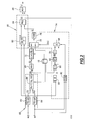
- FIG. 2 Such a control device is illustrated in FIG. 2.
- the control device comprises a unit 60 for determining the radius of curvature Rc at the pair of wheels with which it is associated.
- control device comprises means 68 for checking and correcting the numerical results delivered by the calculation means 66.
- the means 68 are suitable for selecting the maximum between the calculated radius of curvature Rc and a predetermined value stored in data storage means 70.
- This value for example equal to 25 m, is determined by the characteristics of the rail network.
- the resulting radius of curvature Rc of this selection is then delivered to means 72 for determining a limit speed V L for the train.
- the means 72 comprise for example a predetermined map of speed values as a function of values of radius of curvature determined experimentally.
- the limit speed V L is then delivered to a unit 74 for activating / deactivating the speed limitation of the train.
- the unit 74 comprises means 76 for selecting from this limit speed V L and a predetermined value stored in the data storage means 70. This selection is made according to a selection signal Sel, as will be explained in more detail later.
- the means 76 deliver the selected value to means 78 for filtering the output of the selection means 76.
- These means 78 comprise, for example, a filter implementing a time ramp for continuously switching from a previously selected value to a value newly selected by the means 76. This makes it possible to compensate for the effects of a discontinuous switching between two values of the output of the selection means 76.
- the speed limit ⁇ L at the output of the filtering means 78 is delivered to a unit 80 for limiting the speed of the train.
- the limitation unit 80 comprises means 82 for determining the speed of the train V, for example adapted to calculate the average of the longitudinal speeds Vg and Vd determined by the means 62, 64 for determining them.
- the unit 80 also comprises regulating means 84 receiving the limit speed ⁇ L of the attenuation means 78 as setpoint and the speed V of the train as a measurement.
- the regulation means 84 receive the speed V of the train of acquisition or determination means conventionally present in the train, so that the unit 80 does not include the means 82 for determining this speed.
- the means 84 are able to calculate as a function of the speed V of the train and the limit speed ⁇ L a DC control torque setpoint for the engines of the train from a predetermined regulation law.
- This regulation law is determined so that the application of the DC regulation setpoint as a control signal of the motors has the effect that the speed V of the train is regulated on the limit speed ⁇ L.
- This regulation law is also advantageously determined for the speed V does not exceed the limit speed ⁇ L.
- the DC torque setpoint is delivered to means 86 for selecting the minimum of the latter and a CCC torque setpoint delivered by the train driver by means of the cockpit torque request lever.
- the determination of the longitudinal speed thereof may be imprecise or even erroneous.
- the set of calculations based on such a speed is then also unsatisfactory.
- the activation / deactivation unit 74 is adapted to activate or deactivate the speed limitation of the vehicle vis-à-vis the speed V L determined by the means 72 for determining according to predetermined conditions relating to the sliding of the right wheels. and left of the pair of wheels.
- the unit 74 comprises for this purpose means 88 for determining a value G representative of the sliding of the right and left wheels.
- the means 88 deliver the calculated value G to means 90 for comparing it to a predetermined threshold value, for example equal to 1.8, stored in the storage means 70.
- the result of this comparison is delivered to a time counter 92, which is triggered as soon as the value G is lower than its threshold value.
- the counter 92 delivers its counter value to means 94 for comparing it to a predetermined threshold value, for example 2s, stored in the storage means 70.
- This threshold value is also determined experimentally and corresponds to the time at the end of which it is substantially certain that none of the wheels slip.
- the unit 74 also comprises means 96 for diagnosing the operating state of the rotational speed sensors associated with the wheels, for example as a function of the measurements ⁇ g , ⁇ d delivered by these, as is known per se. .
- the results of the comparison of the means 90 and 94 and the result of the diagnosis of the operating state of the rotational speed sensors are delivered to means 98 performing the AND function and delivering the selection signal Sel to the selection means 76.
- the means 76 select the limit speed V L determined by the means 72.
- the predetermined value received by the selection means 76 from the storage means 70 is selected.
- This value which is the maximum speed allowed on the network, for example 70 km / h, is sufficiently high for the DC torque setpoint calculated by the means 84 to be greater than the CCC torque setpoint delivered by the driver.
- the setpoint CCC is selected by the means 80 and the limitation implemented by the unit 80 is thus deactivated.
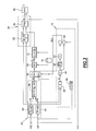
- FIG. 3 illustrates another embodiment of the control device according to the invention. This embodiment differs from that described above in that the activation / deactivation of the speed limitation as a function of the sliding of the wheels of the pair of wheels is performed at the output of the unit 60 for determining the radius of curvature Rc.
- the activation / deactivation unit 74 comprises selection means 99 which receive, as input, the radius of curvature Rc calculated by the unit 60 and a predetermined value of radius of curvature stored in FIGS. means 70 for storing data.
- the means 99 are suitable for selecting, and for delivering to the means 68, one or the other of the values received as input as a function of a signal Sel determined in a similar manner by the same elements of the unit 74 described. previously in relation to Figure 2.
- the means 99 select the radius of curvature Rc determined by the means 60.
- the means 99 select the input value stored in the storage means 70.
- This value is determined to be sufficiently large, for example equal to 1000 km, for its use as a radius of curvature in the following calculation elements to deactivate the speed limitation of the train.
- the torque setpoint C is then delivered to the motors for controlling them.
- the train is equipped with a plurality of devices according to the invention, each associated with a selected pair of mechanically independent wheels and arranged vis-à-vis, the set of torque setpoints C determined by these devices is delivered means for selecting the minimum of these sets of torque C.
- the means 86 for selecting the minimum between the control torque setpoint CC and the setpoint CCC delivered by the driver of any one of the plurality of devices are adapted to receive the regulation torque commands CCC from the other devices. and select the minimum of these and the CCC torque setpoint issued by the driver.
- the selected minimum of the torque setpoints is then delivered to the motors for controlling them.
- This minimum corresponds to the minimum of the speed limits determined by the plurality of devices so that the speed of the vehicle does not exceed this minimum of the limit speeds.
- a step 100 of initialization the various elements of the system are activated.
- a next step 102 an acquisition of the rotational speeds ⁇ g , ⁇ d of the right and left wheels of each selected pair of wheels is performed.
- the longitudinal speeds V d , V g of the wheel pair are then determined, as is the radius of curvature Rc, the value G representative of the sliding of the wheels of the pair of wheels, the diagnosis of the operating state. rotational speed sensors associated with these wheels and the speed V of the train.
- the maximum Rc between the radius of curvature Rc determined and the threshold value associated with is selected, and the limit speed V L determined according to this maximum.
- the conditions on the wheel slip are then tested at 108, and if these are satisfied, the limit speed V L is selected at 110. Otherwise the predetermined limit speed value is selected at 110.
- the next step 112 of the operation is then the calculation of the DC torque setpoint as a function of the speed V of the train and the selected value ⁇ L for the limit speed.
- This step 112 is then followed at 114 by the selection of the minimum between the torque setpoint CC and the setpoint CCC delivered by the train driver.
- Step 114 then loops back to acquisition step 102 for the execution of a new calculation cycle.
- the torque setpoint selected at 114 is then delivered, at 116, to the means for selecting the minimum torque setpoint determined for all the selected pairs of wheels, and the selected torque setpoint delivered to the control means of the train engines. .
- the preceding step 106 consists first of all in testing the conditions on the sliding of the wheels and in selecting the radius of curvature determined by the means 60 if they are satisfied or to select the value of radius of curvature stored in the storage means 70 otherwise.
- the maximum Rc between the value selected by the means 99 and the value stored in the means 70 associated with the means 68 is then selected and the limit speed V L is determined as a function of this maximum.
- Step 106 then loops directly to step 112 previously described.
- FIG. 5 Another embodiment of the train speed control system as a function of the wheel speeds of a plurality of selected pairs of mechanically independent right and left wheels is illustrated in FIG. 5.
- the system of FIG. 5 comprises elements identical to those described with reference to FIG. 3.
- the elements identical to those of FIG. 3 are referenced by the same numbers and are not described here for the sake of brevity.
- This system comprises at least one device of the type described above in relation with FIG. 3 associated with a selected pair of wheels of the plurality of wheel pairs, the part of this device capable of calculating the limit speed for the train and the setpoint of DC control torque being common to the set of selected pairs of wheels, as explained in more detail below.
- Each pair of wheels selected, for example 3 in number, is associated with a device 200a, 200b, 200c able to determine the radius of curvature Rca, Rcb, Rcc of the track at the level of the pair of wheels and a signal Ta, Tb, Tc, representative of the occurrence of a slip of the pair of wheels.
- This device 200a, 200b, 200c comprises for this purpose a unit 60 for determining the radius of curvature at the level of the pair of wheels, means 70 for storing data, and an activation / deactivation unit 74 described in connection with FIG. 3, namely means 88 for determining a value representative of the wheel slip of the pair of wheels, comparison means 90, a time counter 92, comparison means 94, diagnostic means 96, means 98 performing the AND function and delivering a selection signal Ta, Tb, Tc and selection means 99 between the radius of curvature Rc determined by the unit 60 and a predetermined value of radius of curvature according to the selection signal issued by the means 98, as described above.
- the system also includes a device 210 for controlling the speed of the train.
- This device 210 comprises a limitation unit 80 identical to that of FIGS. 2 and 3.
- This unit comprises means 82 for determining the speed of the train as a function of the longitudinal speeds of the right and left wheels determined by the unit 60 for determining the speed of the train. radius of curvature of any of the devices 200a, 200b, 200c associated with a pair of wheels.
- the device 210 also comprises selection means 212 receiving the radii of curvature Rca, Rcb, Rcc selected by the means 99 for selecting the devices 200a, 200b, 200c and adapted to select the minimum of these.
- selection means 212 are connected to means 68 for selecting the maximum between the minimum of the radii of curvature selected by the means 212 and a predetermined value stored in storage means 214, as described above.
- the device 110 also comprises means 72 for determining a limit speed V L connected to the means 68, in a manner identical to that described with reference to FIGS. 2 and 3.
- the device 210 also comprises means 216 which receive the signals Ta, Tb, Tc for selecting the means 98 performing the AND function of the devices 200a, 200b, 200c associated with the selected pairs of wheels.
- the means 216 are suitable for inverting each of the signals Ta, Tb, Tc received and performing the AND function of the inverted signals.
- the means 216 deliver their result to selection means 218.
- These means 218 receive the output of the means 72 and a value of the storage means 214 and are adapted to select one or the other of the received values as a function of the value delivered by the means 216, that is to say the output of the means 72 if the value delivered by the means 216 is 0 and the value of the storage means 214 otherwise, and to deliver their output to the means 84 for regulating the unit 80, as described above.
- the limitation of the speed of the train is carried out as a function of the minimum of the radii of curvature calculated at the level of the selected pairs of wheels and the detection of the sliding of at least one pair of wheels has the effect that this pair of wheels is not not taken into account for the limitation of the speed of the train. If all the wheel pairs slip, the limitation is disabled.
- the operation of the system just described is similar to that described with reference to FIG. 4 except that it comprises an intermediate step for selecting the minimum of the radii of curvature selected by the means 99 for selecting the devices 200a, 200b , 200c of determining the radius of curvature, triggered following the step 104, the selected minimum radius of curvature being used for the determination of the limit speed V L in the step 112 as previously described in connection with Figure 4.
- the step 116 of the operation of the system just described is also modified and consists of delivering the torque setpoint selected at 114 to the engine control means of the train.
- the device and the system according to the invention just described are applicable to all types of railway vehicles comprising at least one pair of mechanically independent wheels and arranged vis-à-vis the vehicle .
Landscapes
- Engineering & Computer Science (AREA)
- Mechanical Engineering (AREA)
- Life Sciences & Earth Sciences (AREA)
- Sustainable Development (AREA)
- Sustainable Energy (AREA)
- Power Engineering (AREA)
- Transportation (AREA)
- Electric Propulsion And Braking For Vehicles (AREA)
- Train Traffic Observation, Control, And Security (AREA)
- Control Of Linear Motors (AREA)
Applications Claiming Priority (1)
| Application Number | Priority Date | Filing Date | Title |
|---|---|---|---|
| FR0412203A FR2877885B1 (fr) | 2004-11-17 | 2004-11-17 | Dispositif et procede de controle de la vitesse d'un vehicule ferroviaire et systeme comprenant de tels dispositifs. |
Publications (2)
| Publication Number | Publication Date |
|---|---|
| EP1659018A1 true EP1659018A1 (de) | 2006-05-24 |
| EP1659018B1 EP1659018B1 (de) | 2009-04-15 |
Family
ID=34953319
Family Applications (1)
| Application Number | Title | Priority Date | Filing Date |
|---|---|---|---|
| EP05292408A Expired - Lifetime EP1659018B1 (de) | 2004-11-17 | 2005-11-14 | Vorrichtung und Verfahren zur Regelung der Geschwindigkeit eines Schienenfahrzeugs und solche Vorrichtung enthaltende Systeme |
Country Status (6)
| Country | Link |
|---|---|
| EP (1) | EP1659018B1 (de) |
| AT (1) | ATE428598T1 (de) |
| AU (1) | AU2005234619B2 (de) |
| DE (1) | DE602005013890D1 (de) |
| ES (1) | ES2325545T3 (de) |
| FR (1) | FR2877885B1 (de) |
Cited By (2)
| Publication number | Priority date | Publication date | Assignee | Title |
|---|---|---|---|---|
| CN102122178A (zh) * | 2011-01-11 | 2011-07-13 | 科蒂斯仪器(中国)有限公司 | 一种电动堆高车用电子调速器组件之电子线路 |
| EP4079595A1 (de) * | 2021-04-20 | 2022-10-26 | Siemens Mobility GmbH | Sensoranordnung und verfahren zur positionsbestimmung für ein schienenfahrzeug |
Families Citing this family (1)
| Publication number | Priority date | Publication date | Assignee | Title |
|---|---|---|---|---|
| DE102019213586A1 (de) * | 2019-09-06 | 2021-03-11 | Siemens Mobility GmbH | Verfahren, Vorrichtung und Schienenfahrzeug |
Citations (4)
| Publication number | Priority date | Publication date | Assignee | Title |
|---|---|---|---|---|
| WO1999014093A1 (en) * | 1997-09-12 | 1999-03-25 | New York Air Brake Corporation | Method of optimizing train operation and training |
| GB2371121A (en) * | 2001-01-13 | 2002-07-17 | Dawe John | Railway train control system |
| US6456923B1 (en) * | 1998-09-02 | 2002-09-24 | Zf Friedrichshafen Ag | Method for detecting cornering for a vehicle with an automatic transmission |
| US20040030483A1 (en) * | 2002-08-02 | 2004-02-12 | Christian Muehlbauer | Method for controlling the speed of a vehicle |
-
2004
- 2004-11-17 FR FR0412203A patent/FR2877885B1/fr not_active Expired - Fee Related
-
2005
- 2005-11-14 ES ES05292408T patent/ES2325545T3/es not_active Expired - Lifetime
- 2005-11-14 AT AT05292408T patent/ATE428598T1/de active
- 2005-11-14 DE DE602005013890T patent/DE602005013890D1/de not_active Expired - Lifetime
- 2005-11-14 EP EP05292408A patent/EP1659018B1/de not_active Expired - Lifetime
- 2005-11-15 AU AU2005234619A patent/AU2005234619B2/en not_active Ceased
Patent Citations (4)
| Publication number | Priority date | Publication date | Assignee | Title |
|---|---|---|---|---|
| WO1999014093A1 (en) * | 1997-09-12 | 1999-03-25 | New York Air Brake Corporation | Method of optimizing train operation and training |
| US6456923B1 (en) * | 1998-09-02 | 2002-09-24 | Zf Friedrichshafen Ag | Method for detecting cornering for a vehicle with an automatic transmission |
| GB2371121A (en) * | 2001-01-13 | 2002-07-17 | Dawe John | Railway train control system |
| US20040030483A1 (en) * | 2002-08-02 | 2004-02-12 | Christian Muehlbauer | Method for controlling the speed of a vehicle |
Cited By (3)
| Publication number | Priority date | Publication date | Assignee | Title |
|---|---|---|---|---|
| CN102122178A (zh) * | 2011-01-11 | 2011-07-13 | 科蒂斯仪器(中国)有限公司 | 一种电动堆高车用电子调速器组件之电子线路 |
| CN102122178B (zh) * | 2011-01-11 | 2013-09-18 | 科蒂斯仪器(中国)有限公司 | 一种电动堆高车用电子调速器组件之电子线路 |
| EP4079595A1 (de) * | 2021-04-20 | 2022-10-26 | Siemens Mobility GmbH | Sensoranordnung und verfahren zur positionsbestimmung für ein schienenfahrzeug |
Also Published As
| Publication number | Publication date |
|---|---|
| AU2005234619B2 (en) | 2012-01-19 |
| FR2877885A1 (fr) | 2006-05-19 |
| ES2325545T3 (es) | 2009-09-08 |
| ATE428598T1 (de) | 2009-05-15 |
| DE602005013890D1 (de) | 2009-05-28 |
| AU2005234619A1 (en) | 2006-06-01 |
| FR2877885B1 (fr) | 2007-03-30 |
| EP1659018B1 (de) | 2009-04-15 |
Similar Documents
| Publication | Publication Date | Title |
|---|---|---|
| EP2219930B1 (de) | Vorrichtung zum messen der bewegung eines selbstgesteuerten fahrzeugs | |
| EP2758257B1 (de) | Verfahren zur schätzung des rollwiderstandes eines fahrzeugrades | |
| EP2895826B1 (de) | Vorrichtung und verfahren zur schätzung der ladung eines kraftfahrzeugs | |
| WO2014195605A1 (fr) | Procédé et dispositif d'estimation d'un état d'usure d'au moins un pneu de véhicule automobile | |
| FR2857090A1 (fr) | Procede et dispositif d'estimation de la masse totale d'un vehicule automobile | |
| EP4077086B1 (de) | Verfahren zur bestimmung eines geschwindigkeitsprofils eines kraftfahrzeuges mit nicht vorgegebener beschleunigung | |
| EP2660121A1 (de) | Verfahren zum Absichern der Umsetzung eines Schienenfahrzeugs, und Schienenfahrzeug | |
| EP1894800B1 (de) | Fahrzeug mit Mitteln zum Ermitteln einer Neigung, auf die es sich bewegt | |
| FR3095510A1 (fr) | Procédé d’estimation d’un index représentatif du comportement frictionnel d’un véhicule sur une route | |
| EP1659018B1 (de) | Vorrichtung und Verfahren zur Regelung der Geschwindigkeit eines Schienenfahrzeugs und solche Vorrichtung enthaltende Systeme | |
| EP2307253B1 (de) | Vorrichtung zur bestimmung der querbeschleunigung eines motorfahrzeugs und entsprechendes verfahren | |
| EP1832493B1 (de) | System und Verfahren zur Überprüfung der Zugvollständigkeit | |
| EP0919814B1 (de) | Verfahren zur Abschätzung der Geschwindigkeit eines Fahrzeuges oder mehrerer miteinander verbundener Fahrzeuge | |
| EP1597133B1 (de) | Verfahren und system zum abschätzen der winkelposition eines lenkrads an einem kraftfahrzeug | |
| EP2082939B1 (de) | Verfahren und System zur Abschätzung der Haftung in einem Kraftfahrzeug | |
| FR2871889A1 (fr) | Systeme de determination de la vitesse longitudinale d'un vehicule a roues | |
| WO2007063231A1 (fr) | Procede et dispositif d'estimation de la vitesse longitudinale d'un vehicule automobile | |
| EP1109025B1 (de) | Verfahren zur Bestimmung von Längsgeschwindigkeiten und -beschleunigungen sowie der Gierraten eines Fahrzeugs | |
| EP2830895B1 (de) | Verfahren zur abschätzung des rollwiderstandes eines kraftfahrzeugsrads | |
| EP4343287B1 (de) | Verfahren und system zur bestimmung der masse eines fahrzeugs | |
| EP1538042B1 (de) | System und Verfahren zur Steuerung der Beschleunigung eines Kraftfahrzeugs an einem Gefälle | |
| WO2025140826A1 (fr) | Procédé pour amélioration de la sélection de cible pour un contrôle adaptatif de vitesse | |
| EP3971007A1 (de) | Verfahren zur steuerung einer funktion eines kraftfahrzeugs | |
| WO2008040901A1 (fr) | Procede de detection de reprise d'adherence d'une roue de vehicule automobile et dispositif associe | |
| FR2920707A3 (fr) | Procede de detection de l'adherence d'une roue de vehicule automobile |
Legal Events
| Date | Code | Title | Description |
|---|---|---|---|
| PUAI | Public reference made under article 153(3) epc to a published international application that has entered the european phase |
Free format text: ORIGINAL CODE: 0009012 |
|
| AK | Designated contracting states |
Kind code of ref document: A1 Designated state(s): AT BE BG CH CY CZ DE DK EE ES FI FR GB GR HU IE IS IT LI LT LU LV MC NL PL PT RO SE SI SK TR |
|
| AX | Request for extension of the european patent |
Extension state: AL BA HR MK YU |
|
| 17P | Request for examination filed |
Effective date: 20061117 |
|
| AKX | Designation fees paid |
Designated state(s): AT BE BG CH CY CZ DE DK EE ES FI FR GB GR HU IE IS IT LI LT LU LV MC NL PL PT RO SE SI SK TR |
|
| AXX | Extension fees paid |
Extension state: HR Payment date: 20061117 |
|
| 17Q | First examination report despatched |
Effective date: 20070129 |
|
| GRAP | Despatch of communication of intention to grant a patent |
Free format text: ORIGINAL CODE: EPIDOSNIGR1 |
|
| GRAS | Grant fee paid |
Free format text: ORIGINAL CODE: EPIDOSNIGR3 |
|
| GRAA | (expected) grant |
Free format text: ORIGINAL CODE: 0009210 |
|
| AK | Designated contracting states |
Kind code of ref document: B1 Designated state(s): AT BE BG CH CY CZ DE DK EE ES FI FR GB GR HU IE IS IT LI LT LU LV MC NL PL PT RO SE SI SK TR |
|
| AX | Request for extension of the european patent |
Extension state: HR |
|
| REG | Reference to a national code |
Ref country code: GB Ref legal event code: FG4D Free format text: NOT ENGLISH Ref country code: CH Ref legal event code: EP |
|
| REG | Reference to a national code |
Ref country code: IE Ref legal event code: FG4D |
|
| REF | Corresponds to: |
Ref document number: 602005013890 Country of ref document: DE Date of ref document: 20090528 Kind code of ref document: P |
|
| REG | Reference to a national code |
Ref country code: RO Ref legal event code: EPE |
|
| REG | Reference to a national code |
Ref country code: SE Ref legal event code: TRGR |
|
| REG | Reference to a national code |
Ref country code: ES Ref legal event code: FG2A Ref document number: 2325545 Country of ref document: ES Kind code of ref document: T3 |
|
| NLV1 | Nl: lapsed or annulled due to failure to fulfill the requirements of art. 29p and 29m of the patents act | ||
| PG25 | Lapsed in a contracting state [announced via postgrant information from national office to epo] |
Ref country code: LT Free format text: LAPSE BECAUSE OF FAILURE TO SUBMIT A TRANSLATION OF THE DESCRIPTION OR TO PAY THE FEE WITHIN THE PRESCRIBED TIME-LIMIT Effective date: 20090415 Ref country code: FI Free format text: LAPSE BECAUSE OF FAILURE TO SUBMIT A TRANSLATION OF THE DESCRIPTION OR TO PAY THE FEE WITHIN THE PRESCRIBED TIME-LIMIT Effective date: 20090415 Ref country code: PT Free format text: LAPSE BECAUSE OF FAILURE TO SUBMIT A TRANSLATION OF THE DESCRIPTION OR TO PAY THE FEE WITHIN THE PRESCRIBED TIME-LIMIT Effective date: 20090915 |
|
| PG25 | Lapsed in a contracting state [announced via postgrant information from national office to epo] |
Ref country code: IS Free format text: LAPSE BECAUSE OF FAILURE TO SUBMIT A TRANSLATION OF THE DESCRIPTION OR TO PAY THE FEE WITHIN THE PRESCRIBED TIME-LIMIT Effective date: 20090815 Ref country code: PL Free format text: LAPSE BECAUSE OF FAILURE TO SUBMIT A TRANSLATION OF THE DESCRIPTION OR TO PAY THE FEE WITHIN THE PRESCRIBED TIME-LIMIT Effective date: 20090415 Ref country code: NL Free format text: LAPSE BECAUSE OF FAILURE TO SUBMIT A TRANSLATION OF THE DESCRIPTION OR TO PAY THE FEE WITHIN THE PRESCRIBED TIME-LIMIT Effective date: 20090415 Ref country code: SI Free format text: LAPSE BECAUSE OF FAILURE TO SUBMIT A TRANSLATION OF THE DESCRIPTION OR TO PAY THE FEE WITHIN THE PRESCRIBED TIME-LIMIT Effective date: 20090415 Ref country code: LV Free format text: LAPSE BECAUSE OF FAILURE TO SUBMIT A TRANSLATION OF THE DESCRIPTION OR TO PAY THE FEE WITHIN THE PRESCRIBED TIME-LIMIT Effective date: 20090415 |
|
| REG | Reference to a national code |
Ref country code: IE Ref legal event code: FD4D |
|
| PG25 | Lapsed in a contracting state [announced via postgrant information from national office to epo] |
Ref country code: IE Free format text: LAPSE BECAUSE OF FAILURE TO SUBMIT A TRANSLATION OF THE DESCRIPTION OR TO PAY THE FEE WITHIN THE PRESCRIBED TIME-LIMIT Effective date: 20090415 Ref country code: EE Free format text: LAPSE BECAUSE OF FAILURE TO SUBMIT A TRANSLATION OF THE DESCRIPTION OR TO PAY THE FEE WITHIN THE PRESCRIBED TIME-LIMIT Effective date: 20090415 Ref country code: CZ Free format text: LAPSE BECAUSE OF FAILURE TO SUBMIT A TRANSLATION OF THE DESCRIPTION OR TO PAY THE FEE WITHIN THE PRESCRIBED TIME-LIMIT Effective date: 20090415 Ref country code: DK Free format text: LAPSE BECAUSE OF FAILURE TO SUBMIT A TRANSLATION OF THE DESCRIPTION OR TO PAY THE FEE WITHIN THE PRESCRIBED TIME-LIMIT Effective date: 20090415 |
|
| PLBE | No opposition filed within time limit |
Free format text: ORIGINAL CODE: 0009261 |
|
| STAA | Information on the status of an ep patent application or granted ep patent |
Free format text: STATUS: NO OPPOSITION FILED WITHIN TIME LIMIT |
|
| PG25 | Lapsed in a contracting state [announced via postgrant information from national office to epo] |
Ref country code: SK Free format text: LAPSE BECAUSE OF FAILURE TO SUBMIT A TRANSLATION OF THE DESCRIPTION OR TO PAY THE FEE WITHIN THE PRESCRIBED TIME-LIMIT Effective date: 20090415 |
|
| REG | Reference to a national code |
Ref country code: HU Ref legal event code: AG4A Ref document number: E006687 Country of ref document: HU |
|
| 26N | No opposition filed |
Effective date: 20100118 |
|
| PG25 | Lapsed in a contracting state [announced via postgrant information from national office to epo] |
Ref country code: BG Free format text: LAPSE BECAUSE OF FAILURE TO SUBMIT A TRANSLATION OF THE DESCRIPTION OR TO PAY THE FEE WITHIN THE PRESCRIBED TIME-LIMIT Effective date: 20090715 |
|
| BERE | Be: lapsed |
Owner name: ALSTOM TRANSPORT SA Effective date: 20091130 |
|
| PG25 | Lapsed in a contracting state [announced via postgrant information from national office to epo] |
Ref country code: MC Free format text: LAPSE BECAUSE OF NON-PAYMENT OF DUE FEES Effective date: 20091130 |
|
| REG | Reference to a national code |
Ref country code: CH Ref legal event code: PL |
|
| GBPC | Gb: european patent ceased through non-payment of renewal fee |
Effective date: 20091114 |
|
| REG | Reference to a national code |
Ref country code: FR Ref legal event code: ST Effective date: 20100730 |
|
| PG25 | Lapsed in a contracting state [announced via postgrant information from national office to epo] |
Ref country code: FR Free format text: LAPSE BECAUSE OF NON-PAYMENT OF DUE FEES Effective date: 20091130 Ref country code: GR Free format text: LAPSE BECAUSE OF FAILURE TO SUBMIT A TRANSLATION OF THE DESCRIPTION OR TO PAY THE FEE WITHIN THE PRESCRIBED TIME-LIMIT Effective date: 20090716 Ref country code: CH Free format text: LAPSE BECAUSE OF NON-PAYMENT OF DUE FEES Effective date: 20091130 Ref country code: LI Free format text: LAPSE BECAUSE OF NON-PAYMENT OF DUE FEES Effective date: 20091130 Ref country code: BE Free format text: LAPSE BECAUSE OF NON-PAYMENT OF DUE FEES Effective date: 20091130 |
|
| PG25 | Lapsed in a contracting state [announced via postgrant information from national office to epo] |
Ref country code: GB Free format text: LAPSE BECAUSE OF NON-PAYMENT OF DUE FEES Effective date: 20091114 |
|
| PG25 | Lapsed in a contracting state [announced via postgrant information from national office to epo] |
Ref country code: LU Free format text: LAPSE BECAUSE OF NON-PAYMENT OF DUE FEES Effective date: 20091114 |
|
| PG25 | Lapsed in a contracting state [announced via postgrant information from national office to epo] |
Ref country code: TR Free format text: LAPSE BECAUSE OF FAILURE TO SUBMIT A TRANSLATION OF THE DESCRIPTION OR TO PAY THE FEE WITHIN THE PRESCRIBED TIME-LIMIT Effective date: 20090415 |
|
| PG25 | Lapsed in a contracting state [announced via postgrant information from national office to epo] |
Ref country code: CY Free format text: LAPSE BECAUSE OF FAILURE TO SUBMIT A TRANSLATION OF THE DESCRIPTION OR TO PAY THE FEE WITHIN THE PRESCRIBED TIME-LIMIT Effective date: 20090415 |
|
| REG | Reference to a national code |
Ref country code: ES Ref legal event code: PC2A Owner name: ALSTOM TRANSPORT TECHNOLOGIES Effective date: 20140211 |
|
| REG | Reference to a national code |
Ref country code: HU Ref legal event code: FH1C Free format text: FORMER REPRESENTATIVE(S): DR. HARANGOZO GABOR, DANUBIA SZABADALMI ES JOGI IRODA KFT., HU Representative=s name: DANUBIA SZABADALMI ES JOGI IRODA KFT., HU Ref country code: HU Ref legal event code: GB9C Owner name: ALSTOM TRANSPORT TECHNOLOGIES, FR Free format text: FORMER OWNER(S): ALSTOM TRANSPORT S.A., FR |
|
| REG | Reference to a national code |
Ref country code: DE Ref legal event code: R081 Ref document number: 602005013890 Country of ref document: DE Owner name: ALSTOM TRANSPORT TECHNOLOGIES, FR Free format text: FORMER OWNER: ALSTOM TRANSPORT S.A., LEVALLOIS-PERRET, FR Effective date: 20140213 |
|
| REG | Reference to a national code |
Ref country code: AT Ref legal event code: PC Ref document number: 428598 Country of ref document: AT Kind code of ref document: T Owner name: ALSTOM TRANSPORT TECHNOLOGIES, FR Effective date: 20140919 |
|
| REG | Reference to a national code |
Ref country code: HU Ref legal event code: HC9C Owner name: ALSTOM TRANSPORT TECHNOLOGIES, FR Free format text: FORMER OWNER(S): ALSTOM TRANSPORT S.A., FR; ALSTOM TRANSPORT TECHNOLOGIES, FR |
|
| REG | Reference to a national code |
Ref country code: DE Ref legal event code: R081 Ref document number: 602005013890 Country of ref document: DE Owner name: ALSTOM TRANSPORT TECHNOLOGIES, FR Free format text: FORMER OWNER: ALSTOM TRANSPORT TECHNOLOGIES, LEVALLOIS-PERRET, FR |
|
| PGFP | Annual fee paid to national office [announced via postgrant information from national office to epo] |
Ref country code: AT Payment date: 20201119 Year of fee payment: 16 Ref country code: DE Payment date: 20201119 Year of fee payment: 16 Ref country code: HU Payment date: 20201218 Year of fee payment: 16 Ref country code: SE Payment date: 20201125 Year of fee payment: 16 Ref country code: RO Payment date: 20201111 Year of fee payment: 16 Ref country code: IT Payment date: 20201124 Year of fee payment: 16 |
|
| PGFP | Annual fee paid to national office [announced via postgrant information from national office to epo] |
Ref country code: ES Payment date: 20210122 Year of fee payment: 16 |
|
| REG | Reference to a national code |
Ref country code: DE Ref legal event code: R119 Ref document number: 602005013890 Country of ref document: DE |
|
| REG | Reference to a national code |
Ref country code: AT Ref legal event code: MM01 Ref document number: 428598 Country of ref document: AT Kind code of ref document: T Effective date: 20211114 |
|
| PG25 | Lapsed in a contracting state [announced via postgrant information from national office to epo] |
Ref country code: SE Free format text: LAPSE BECAUSE OF NON-PAYMENT OF DUE FEES Effective date: 20211115 Ref country code: RO Free format text: LAPSE BECAUSE OF NON-PAYMENT OF DUE FEES Effective date: 20211114 Ref country code: HU Free format text: LAPSE BECAUSE OF NON-PAYMENT OF DUE FEES Effective date: 20211115 |
|
| PG25 | Lapsed in a contracting state [announced via postgrant information from national office to epo] |
Ref country code: AT Free format text: LAPSE BECAUSE OF NON-PAYMENT OF DUE FEES Effective date: 20211114 |
|
| PG25 | Lapsed in a contracting state [announced via postgrant information from national office to epo] |
Ref country code: DE Free format text: LAPSE BECAUSE OF NON-PAYMENT OF DUE FEES Effective date: 20220601 |
|
| PG25 | Lapsed in a contracting state [announced via postgrant information from national office to epo] |
Ref country code: IT Free format text: LAPSE BECAUSE OF NON-PAYMENT OF DUE FEES Effective date: 20211114 |
|
| REG | Reference to a national code |
Ref country code: ES Ref legal event code: FD2A Effective date: 20230210 |
|
| PG25 | Lapsed in a contracting state [announced via postgrant information from national office to epo] |
Ref country code: ES Free format text: LAPSE BECAUSE OF NON-PAYMENT OF DUE FEES Effective date: 20211115 |