EP1659227A1 - Dispositif de chasse sous pression - Google Patents
Dispositif de chasse sous pression Download PDFInfo
- Publication number
- EP1659227A1 EP1659227A1 EP04405717A EP04405717A EP1659227A1 EP 1659227 A1 EP1659227 A1 EP 1659227A1 EP 04405717 A EP04405717 A EP 04405717A EP 04405717 A EP04405717 A EP 04405717A EP 1659227 A1 EP1659227 A1 EP 1659227A1
- Authority
- EP
- European Patent Office
- Prior art keywords
- pressure
- flushing device
- pressure chamber
- container
- cylindrical
- Prior art date
- Legal status (The legal status is an assumption and is not a legal conclusion. Google has not performed a legal analysis and makes no representation as to the accuracy of the status listed.)
- Withdrawn
Links
Images
Classifications
-
- E—FIXED CONSTRUCTIONS
- E03—WATER SUPPLY; SEWERAGE
- E03D—WATER-CLOSETS OR URINALS WITH FLUSHING DEVICES; FLUSHING VALVES THEREFOR
- E03D3/00—Flushing devices operated by pressure of the water supply system flushing valves not connected to the water-supply main, also if air is blown in the water seal for a quick flushing
- E03D3/10—Flushing devices with pressure-operated reservoir, e.g. air chamber
Definitions
- the invention relates to a Druck Wellvorraum with a pressure vessel having a pressure chamber for receiving rinse water, with an inlet valve with which the pressure vessel can be filled with rinse water, with an outlet valve and with an actuator for triggering a flushing.
- Pressure flushing devices of the type mentioned are known for example from WO 2004/033808 and US 5,857,224 and have proven themselves.
- the rinse water is stored under a pressure of for example 1.5 to 2.5 bar.
- the pressure is maintained by one or more air chambers, which is located in the pressure vessel above the rinse water.
- the rinse water flows through an opening in the bottom of the pressure vessel into the toilet bowl.
- the pressure vessel is automatically filled with rinse water again.
- the rinse water is introduced with the inlet valve from a pressure line in the pressure vessel. In this case, the air in the pressure vessel is compressed and thus built up the desired pressure.
- the flushing is triggered, for example, by pressing a button or non-contact.
- pressure flushing devices Compared with flushing devices in which the flushing water flows into the toilet bowl solely by gravity, pressure flushing devices have the advantage that the flushing water is delivered at a higher speed and thus more effectively can. The greater speed of the rinse water allows a higher cleaning effect.
- a disadvantage of Druck Anlagenvorraumen that due to the relatively high pressure in the pressure vessel, this must be made correspondingly stable. This is not easy to achieve, especially when the pressure vessel is made of plastic.
- the pressure vessel is made of two housing parts, which are interconnected by friction welding.
- the two housing parts are preferably made of plastic here.
- inner walls are provided, which extend through the lower housing part and each connect a front wall and a rear wall with each other. This should give the pressure vessel strength and stability.
- the disadvantage is that the production of such a pressure vessel is comparatively complicated. It has also been shown that in pressure tanks in the filled state wall areas can bulge outwards, which is undesirable.
- the invention has for its object to provide a pressure cistern of the type mentioned, which avoids the disadvantages mentioned.
- the pressure flushing device should thus be produced at elevated pressure resistance of plastic.
- the pressure chamber consists of cylindrical pressure chamber areas which are interconnected in a lower region of the pressure vessel.
- This design of the pressure chamber areas flat side walls can be avoided.
- the cylindrical pressure chamber areas preferably extend over more than half the total height of the pressure vessel.
- at least two cylindrical pressure chamber areas extend over more than two thirds of the height of the pressure vessel.
- the said pressure chamber areas are preferably circular. This makes it possible to ensure substantially equal pressure loads on the wall of the pressure vessel on all sides. Unwanted bulges can thus be avoided.
- the pressure vessel can also be made compact in plastic.
- the pressure vessel consists according to a development of the invention of a container shell and a container base, which are tightly interconnected.
- the cylindrical pressure chamber areas are formed by the container upper part.
- the Verbindulgsstelle between the container top and the container base is preferably located in the lower third and preferably in the lower quarter of the pressure vessel.
- the container lower part forms a connecting channel which connects the cylindrical pressure chamber areas.
- This connecting channel is seen in cross section downwards substantially semicircular. This flat side walls are avoided in the bottom area.
- the connecting channel preferably connects three cylindrical pressure chamber areas with each other.
- Both the container top and the container bottom are preferably made of plastic, for example by injection molding. These two parts are tightly connected to each other, for example by friction welding or hot gas.
- three cylindrical pressure chamber areas are arranged side by side.
- the middle pressure chamber area is used for the storage and receiving of the inlet valve, the outlet valve and the actuator.
- amplification ribs are arranged on the outside between at most two cylindrical pressure chamber regions. These reinforcing ribs are preferably formed in each case on an intermediate wall and located in a recess.
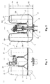
- the pressure flushing device 1 has a pressure vessel 2, which is produced from a container upper part 4 and a container lower part 5.
- the container top 4 and the Container bottom part 5 are for example produced by injection molding and connected in a lower region with a weld 3 tightly together.
- a flushing nozzle 10 is integrally formed on the inside, a valve seat 9 for the drain valve 22 shown in more detail in Fig. 2 forms.
- the outlet valve 22 has a closure body 8, which is raised to trigger a purge in a conventional manner.
- the flushing water located in the pressure vessel 2 is released after triggering a flushing through the Spülstutzen 10 via a rinse sheet, not shown here in a toilet bowl also not shown here.
- the outlet valve 22 is mounted on the container upper part 4. Also on the container upper part 4 is a known inlet valve 7 is mounted. This is connected to a Walser pressure line, not shown here.
- a known inlet valve 7 is mounted on the container upper part 4.
- This is connected to a Walser pressure line, not shown here.
- water flows through a valve housing 14 shown in FIG. 2 into a pressure chamber D of the pressure vessel 2. Air in the pressure chamber D is compressed in this case. Instead of air, a spring may be provided, which is stretched when filling the pressure vessel 2. If the pressure vessel 2 is filled, then the inlet valve 7 closes automatically. The compressed air is in the upper regions 15 of the pressure chamber D shown in FIG.
- an actuator 20 is also mounted, which has two buttons. Pressing one of these buttons will initiate a purge. For example, one button will flush with four liters of rinse water and the other button will flush with six liters of rinse water. There are also other operations, such as a non-contact operation possible.
- the original disclosure in particular regarding the inlet valve and the drain valve will be here also referred to WO 2004/033808 of the applicant.
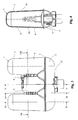
- the container top 4 is formed so that three pressure chamber areas D1, D2 and D3 are formed. In the horizontal cross section, these pressure chamber areas D1, D2 and D3 are each substantially circular over their entire height, as shown in particular in FIG. 7.
- the cylindrical region extends according to FIG. 2 from an upper side 23 to the weld seam 3.
- the corresponding height is indicated in FIG. 2 by H1.
- this height H1 is preferably more than half, preferably more than two-thirds.
- the height H2 of the container base 5 is correspondingly substantially less than half the height H, preferably about one quarter.
- the pressure chamber regions D1, D2 and D3 are arranged in a line, wherein the pressure chamber regions D1 and D3 outside and the pressure chamber region D2 are arranged between them in the middle.
- the pressure chamber areas D1 and D3 are substantially empty and serve to receive the rinsing water or the air in the areas 15.
- the middle pressure chamber area D2 also serves to receive rinsing water and air, but at the same time also for receiving the outlet valve 22.
- is the middle pressure chamber area D2 is less high than the two pressure chamber areas D1 and D3.
- an upper side 23a of the middle pressure chamber region D2 is located below the upper sides 23 of the pressure chamber regions D1 and D3.
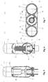
- the pressure chamber areas D1, D2 and D3 are formed by corresponding walls Z1, Z2 and Z3, as shown in FIG. These walls Z1, Z2 and Z3 are connected by two partitions 12. These partitions 12 preferably also extend substantially over the entire height of the pressure chamber D2. As can be seen, these partitions 12 are relatively narrow in horizontal extent. With the ribs 6 arranged on the outside in indentations 16 and in particular molded on, these intermediate walls 12 reinforce the pressure vessel 2. In each case one of the indentations 16 has a plurality of ribs 6 arranged one above the other at a distance from each other. As shown in FIG.
- the connecting channel V connects the pressure chamber regions D1, D2 and D3 to one another, wherein this connecting channel V extends substantially horizontally in the container lower part 5.
- the height H2 of this connection channel V is substantially smaller than the height H1 of the container upper part 4 or the pressure chamber regions D1 and D3.
- the connecting channel is substantially semicircular or circular.
- a bottom 17 of the container base 5 is rounded on all sides. Likewise, no flat wall areas have a front side 18 and a rear side 19 of the pressure vessel 2.
Landscapes
- Health & Medical Sciences (AREA)
- Life Sciences & Earth Sciences (AREA)
- Engineering & Computer Science (AREA)
- Hydrology & Water Resources (AREA)
- Public Health (AREA)
- Water Supply & Treatment (AREA)
- Pressure Vessels And Lids Thereof (AREA)
Priority Applications (4)
| Application Number | Priority Date | Filing Date | Title |
|---|---|---|---|
| EP04405717A EP1659227A1 (fr) | 2004-11-19 | 2004-11-19 | Dispositif de chasse sous pression |
| AU2005218032A AU2005218032A1 (en) | 2004-11-19 | 2005-09-29 | Pressure-flushing device |
| SG200506427A SG122877A1 (en) | 2004-11-19 | 2005-10-04 | Pressure-flushing device |
| US11/251,927 US7171701B2 (en) | 2004-11-19 | 2005-10-18 | Pressure-flushing device |
Applications Claiming Priority (1)
| Application Number | Priority Date | Filing Date | Title |
|---|---|---|---|
| EP04405717A EP1659227A1 (fr) | 2004-11-19 | 2004-11-19 | Dispositif de chasse sous pression |
Publications (1)
| Publication Number | Publication Date |
|---|---|
| EP1659227A1 true EP1659227A1 (fr) | 2006-05-24 |
Family
ID=34932370
Family Applications (1)
| Application Number | Title | Priority Date | Filing Date |
|---|---|---|---|
| EP04405717A Withdrawn EP1659227A1 (fr) | 2004-11-19 | 2004-11-19 | Dispositif de chasse sous pression |
Country Status (4)
| Country | Link |
|---|---|
| US (1) | US7171701B2 (fr) |
| EP (1) | EP1659227A1 (fr) |
| AU (1) | AU2005218032A1 (fr) |
| SG (1) | SG122877A1 (fr) |
Cited By (1)
| Publication number | Priority date | Publication date | Assignee | Title |
|---|---|---|---|---|
| WO2018104411A3 (fr) * | 2016-12-06 | 2019-02-21 | Swiss Aqua Technologies Ag | Système de chasse sous pression pour cuvette de wc |
Families Citing this family (7)
| Publication number | Priority date | Publication date | Assignee | Title |
|---|---|---|---|---|
| ES2276644B1 (es) * | 2007-03-02 | 2009-01-01 | Alfonso Freixer Mascaros | Dispositivo de descarga para inodoro. |
| US8615822B2 (en) * | 2009-05-31 | 2013-12-31 | Fluidmaster, Inc. | Air pressure activated toilet flushing system |
| WO2016163959A2 (fr) * | 2015-04-07 | 2016-10-13 | Pancurák František | Système de chasse de cuvette de toilettes sous pression, avec chasse à ondes de choc |
| WO2018053104A1 (fr) * | 2016-09-14 | 2018-03-22 | Ot Llc | Système de toilettes à faible chasse d'eau |
| US11821190B2 (en) * | 2021-05-21 | 2023-11-21 | Sloan Valve Company | Tank for toilet flushing system and manufacturing method |
| CN218028015U (zh) * | 2022-03-29 | 2022-12-13 | 厦门铱科卫浴科技有限公司 | 压力包排水结构 |
| CA3266177A1 (fr) | 2022-08-29 | 2024-03-07 | Sloan Valve Company | Ensemble inducteur d'air pour réservoir de chasse d'eau sous pression |
Citations (7)
| Publication number | Priority date | Publication date | Assignee | Title |
|---|---|---|---|---|
| US1338638A (en) * | 1919-10-18 | 1920-04-27 | Knell William Franklin | Flushing-valve |
| US3566416A (en) | 1967-09-09 | 1971-03-02 | Pietro Altieri | Water closet apparatus |
| US3890651A (en) * | 1974-03-11 | 1975-06-24 | Robert Arnold Wood | Pressure tank water closet system |
| US5857224A (en) | 1997-10-14 | 1999-01-12 | Sloan Valve Company | Pressure flush tank for use in a toilet enclosure |
| US20010034903A1 (en) * | 1993-04-08 | 2001-11-01 | Martin Raymond Bruce | Pressurized water closet flushing system |
| US6457187B1 (en) | 2000-02-11 | 2002-10-01 | Pulf Water Systems Inc. | Pressurized water closet flushing system |
| WO2004033808A1 (fr) | 2002-10-03 | 2004-04-22 | Geberit Technik Ag | Systeme de chasse pour w.c. a eau sous pression |
Family Cites Families (5)
| Publication number | Priority date | Publication date | Assignee | Title |
|---|---|---|---|---|
| US5361426A (en) * | 1993-04-16 | 1994-11-08 | W/C Technology Corporation | Hydraulically controlled pressurized water closet flushing system |
| US5970527A (en) * | 1997-03-07 | 1999-10-26 | W/C Technology Corporation | Pressurized water closet flushing system |
| US6343387B1 (en) * | 2000-12-06 | 2002-02-05 | W/C Technology Corporation | Volume control for a water closet |
| US6550076B1 (en) * | 2001-09-28 | 2003-04-22 | Sloan Valve Company | Valve assembly for a pressure flush system |
| US6907623B2 (en) * | 2002-10-03 | 2005-06-21 | Geberit Technik Ag | Pressurized water closet flush system |
-
2004
- 2004-11-19 EP EP04405717A patent/EP1659227A1/fr not_active Withdrawn
-
2005
- 2005-09-29 AU AU2005218032A patent/AU2005218032A1/en not_active Abandoned
- 2005-10-04 SG SG200506427A patent/SG122877A1/en unknown
- 2005-10-18 US US11/251,927 patent/US7171701B2/en not_active Expired - Fee Related
Patent Citations (7)
| Publication number | Priority date | Publication date | Assignee | Title |
|---|---|---|---|---|
| US1338638A (en) * | 1919-10-18 | 1920-04-27 | Knell William Franklin | Flushing-valve |
| US3566416A (en) | 1967-09-09 | 1971-03-02 | Pietro Altieri | Water closet apparatus |
| US3890651A (en) * | 1974-03-11 | 1975-06-24 | Robert Arnold Wood | Pressure tank water closet system |
| US20010034903A1 (en) * | 1993-04-08 | 2001-11-01 | Martin Raymond Bruce | Pressurized water closet flushing system |
| US5857224A (en) | 1997-10-14 | 1999-01-12 | Sloan Valve Company | Pressure flush tank for use in a toilet enclosure |
| US6457187B1 (en) | 2000-02-11 | 2002-10-01 | Pulf Water Systems Inc. | Pressurized water closet flushing system |
| WO2004033808A1 (fr) | 2002-10-03 | 2004-04-22 | Geberit Technik Ag | Systeme de chasse pour w.c. a eau sous pression |
Cited By (2)
| Publication number | Priority date | Publication date | Assignee | Title |
|---|---|---|---|---|
| WO2018104411A3 (fr) * | 2016-12-06 | 2019-02-21 | Swiss Aqua Technologies Ag | Système de chasse sous pression pour cuvette de wc |
| CN110139964A (zh) * | 2016-12-06 | 2019-08-16 | 瑞士水技术公司 | 用于马桶的压力冲洗系统 |
Also Published As
| Publication number | Publication date |
|---|---|
| US20060107451A1 (en) | 2006-05-25 |
| AU2005218032A1 (en) | 2006-06-08 |
| US7171701B2 (en) | 2007-02-06 |
| SG122877A1 (en) | 2006-06-29 |
Similar Documents
| Publication | Publication Date | Title |
|---|---|---|
| DE3905611C2 (de) | Kraftstofftank | |
| DE69319856T2 (de) | Spender für fliessfähige Substanz mit verformbarem Kopf | |
| DE60201524T2 (de) | Waschmittelspender für geschirrspülmaschine | |
| AT508350B1 (de) | Zahnbürste | |
| DE3210668A1 (de) | Absperrorgan | |
| WO2002077377A2 (fr) | Chasse d'eau pour toilettes | |
| DE3304027A1 (de) | Passive abgabevorrichtung | |
| DE102013205688A1 (de) | Innenbehälter aus Kunststoff sowie Transport- und Lagerbehälter für Flüssigkeiten mit einem derartigen Innenbehälter | |
| EP0224767B1 (fr) | Dispositif pour l'adjonction d'un désinfectant ou similaire à la rinçure d'un WC | |
| EP1659227A1 (fr) | Dispositif de chasse sous pression | |
| DE10315236A1 (de) | Reservoireinheit | |
| DE2646234A1 (de) | Heizkoerper | |
| EP1549555A1 (fr) | Contenant de grand volume presentant deux parties et un dispositif de soutien au niveau de la jonction entre les deux parties | |
| DE1784700A1 (de) | Wasserbehaelter fuer WC-Becken | |
| DE2325970C3 (de) | Fensterrahmen | |
| EP0737784B1 (fr) | Soupage d'évacuation d'un réservoir de chasse d'eau | |
| EP2422679B1 (fr) | Lave-vaisselle | |
| DE29900260U1 (de) | Spüleinrichtung an einer eine Klosettschüssel aufweisenden Klosettanlage | |
| EP4102000A1 (fr) | Entrée de sol dotée de siphon | |
| DE8707848U1 (de) | Spülvorrichtung für die Wasserspülung von Toiletten | |
| EP1175534B1 (fr) | Systeme de toilettes permettant des economies d'eau | |
| EP1416098B1 (fr) | Bonde siphoide pour installation d'écoulement | |
| EP2059749A1 (fr) | Appareil frigorifique doté d'un réservoir d'eau | |
| EP4095323B1 (fr) | Système de rinçage | |
| DE3907119A1 (de) | Wasserklosett-spuelmechanismus |
Legal Events
| Date | Code | Title | Description |
|---|---|---|---|
| PUAI | Public reference made under article 153(3) epc to a published international application that has entered the european phase |
Free format text: ORIGINAL CODE: 0009012 |
|
| AK | Designated contracting states |
Kind code of ref document: A1 Designated state(s): AT BE BG CH CY CZ DE DK EE ES FI FR GB GR HU IE IS IT LI LU MC NL PL PT RO SE SI SK TR |
|
| AX | Request for extension of the european patent |
Extension state: AL HR LT LV MK YU |
|
| 17P | Request for examination filed |
Effective date: 20060619 |
|
| AKX | Designation fees paid |
Designated state(s): AT BE BG CH CY CZ DE DK EE ES FI FR GB GR HU IE IS IT LI LU MC NL PL PT RO SE SI SK TR |
|
| REG | Reference to a national code |
Ref country code: HK Ref legal event code: DE Ref document number: 1092195 Country of ref document: HK |
|
| 17Q | First examination report despatched |
Effective date: 20081125 |
|
| RAP1 | Party data changed (applicant data changed or rights of an application transferred) |
Owner name: GEBERIT INTERNATIONAL AG |
|
| STAA | Information on the status of an ep patent application or granted ep patent |
Free format text: STATUS: THE APPLICATION IS DEEMED TO BE WITHDRAWN |
|
| 18D | Application deemed to be withdrawn |
Effective date: 20110601 |
|
| REG | Reference to a national code |
Ref country code: HK Ref legal event code: WD Ref document number: 1092195 Country of ref document: HK |