EP1659250B1 - Fenêtre, porte ou analogue avec un renvoi de coin - Google Patents
Fenêtre, porte ou analogue avec un renvoi de coin Download PDFInfo
- Publication number
- EP1659250B1 EP1659250B1 EP05022563A EP05022563A EP1659250B1 EP 1659250 B1 EP1659250 B1 EP 1659250B1 EP 05022563 A EP05022563 A EP 05022563A EP 05022563 A EP05022563 A EP 05022563A EP 1659250 B1 EP1659250 B1 EP 1659250B1
- Authority
- EP
- European Patent Office
- Prior art keywords
- corner guide
- coupling
- connecting pieces
- corner
- door
- Prior art date
- Legal status (The legal status is an assumption and is not a legal conclusion. Google has not performed a legal analysis and makes no representation as to the accuracy of the status listed.)
- Expired - Lifetime
Links
Images



Classifications
-
- E—FIXED CONSTRUCTIONS
- E05—LOCKS; KEYS; WINDOW OR DOOR FITTINGS; SAFES
- E05F—DEVICES FOR MOVING WINGS INTO OPEN OR CLOSED POSITION; CHECKS FOR WINGS; WING FITTINGS NOT OTHERWISE PROVIDED FOR, CONCERNED WITH THE FUNCTIONING OF THE WING
- E05F7/00—Accessories for wings not provided for in other groups of this subclass
- E05F7/08—Means for transmitting movements between vertical and horizontal sliding bars, rods, or cables
-
- E—FIXED CONSTRUCTIONS
- E05—LOCKS; KEYS; WINDOW OR DOOR FITTINGS; SAFES
- E05C—BOLTS OR FASTENING DEVICES FOR WINGS, SPECIALLY FOR DOORS OR WINDOWS
- E05C9/00—Arrangements of simultaneously actuated bolts or other securing devices at well-separated positions on the same wing
- E05C9/08—Arrangements of simultaneously actuated bolts or other securing devices at well-separated positions on the same wing with a rotary bar for actuating the fastening means
-
- E—FIXED CONSTRUCTIONS
- E06—DOORS, WINDOWS, SHUTTERS, OR ROLLER BLINDS IN GENERAL; LADDERS
- E06B—FIXED OR MOVABLE CLOSURES FOR OPENINGS IN BUILDINGS, VEHICLES, FENCES OR LIKE ENCLOSURES IN GENERAL, e.g. DOORS, WINDOWS, BLINDS, GATES
- E06B7/00—Special arrangements or measures in connection with doors or windows
- E06B7/16—Sealing arrangements on wings or parts co-operating with the wings
- E06B7/18—Sealing arrangements on wings or parts co-operating with the wings by means of movable edgings, e.g. draught sealings additionally used for bolting, e.g. by spring force or with operating lever
-
- E—FIXED CONSTRUCTIONS
- E05—LOCKS; KEYS; WINDOW OR DOOR FITTINGS; SAFES
- E05Y—INDEXING SCHEME ASSOCIATED WITH SUBCLASSES E05D AND E05F, RELATING TO CONSTRUCTION ELEMENTS, ELECTRIC CONTROL, POWER SUPPLY, POWER SIGNAL OR TRANSMISSION, USER INTERFACES, MOUNTING OR COUPLING, DETAILS, ACCESSORIES, AUXILIARY OPERATIONS NOT OTHERWISE PROVIDED FOR, APPLICATION THEREOF
- E05Y2900/00—Application of doors, windows, wings or fittings thereof
- E05Y2900/10—Application of doors, windows, wings or fittings thereof for buildings or parts thereof
- E05Y2900/13—Type of wing
- E05Y2900/132—Doors
-
- E—FIXED CONSTRUCTIONS
- E05—LOCKS; KEYS; WINDOW OR DOOR FITTINGS; SAFES
- E05Y—INDEXING SCHEME ASSOCIATED WITH SUBCLASSES E05D AND E05F, RELATING TO CONSTRUCTION ELEMENTS, ELECTRIC CONTROL, POWER SUPPLY, POWER SIGNAL OR TRANSMISSION, USER INTERFACES, MOUNTING OR COUPLING, DETAILS, ACCESSORIES, AUXILIARY OPERATIONS NOT OTHERWISE PROVIDED FOR, APPLICATION THEREOF
- E05Y2900/00—Application of doors, windows, wings or fittings thereof
- E05Y2900/10—Application of doors, windows, wings or fittings thereof for buildings or parts thereof
- E05Y2900/13—Type of wing
- E05Y2900/148—Windows
Definitions
- the invention relates to a window, a door or the like with an openable and closable wing, and a fixed enclosure, with a fitting assembly comprising at least two rotatable rotation elements, wherein the rotation elements in each Falznostiscardi along one side of the window, the door or The like extend and are coupled via a corner linkage, wherein the corner drive has two connecting pieces.
- the invention further relates to a corner drive with the corresponding Eckumlenkungsmerkmalen.
- the corner drive has two bevel gears, which establish the motion coupling.
- the bevel gears each have a connection piece, which is in communication with a fitting.
- the fittings are motion coupled via a pivot with another fitting.
- Object of the present invention is to provide a window, a door or the like with a corner deflection, with a simple connection of the corner deflection is made possible to a rotating element.
- the coupling element is arranged displaceably against a restoring force on the connecting piece.
- the coupling element can be moved against the restoring force, which can be generated by a spring element, on the connecting piece, so that the rotation element can be arranged in the extension of the connection piece. Subsequently, the coupling element can be released so that it slides over one end of the rotating element. The coupling element then sits partly on the connecting piece and partly on the rotary element. By the spring force of the spring element, the coupling element is held in its position of use.
- the coupling element is designed as a sleeve whose inner contour corresponds to the outer contour of the connecting piece and of the rotary element.
- the connection piece and / or the rotation element may have a hexagonal cross-section.
- the inner contour of the sleeve has a hexagonal cross-section.
- the sleeve can be placed with little play on the connection piece and the rotation element and thereby produces a movement coupling.
- the contours of the connecting piece and the rotary element a variety of cross-sectional shapes are conceivable, which allow a rotationally fixed coupling. With a sleeve, the movement coupling can advantageously be made without tools.
- the sleeve may be formed differently at its two ends, so that each end of the sleeve is adapted to the corresponding outer contour of the connecting piece and the rotary member when the connecting piece and the rotary member have different contours.
- connection piece and the rotation element have the same outer contour, since this does not have to pay attention to the orientation of the sleeve during assembly.
- a housing is provided for the corner deflection and the coupling element is supported in a position of use with one end on the housing. This means that the position of use of the coupling element is fixed on the one hand by the spring element and on the other by the housing. An unintentional release of the coupling between corner drive and rotation element is reliably prevented in this way. Instead of a housing and a stop is conceivable, on which the coupling element abuts in a position of use.
- the rotation element may be formed as a locking element, which is arranged rotatably on the wing or the fixed enclosure. Such a locking element can effect a planar locking over the entire length of one side of the window of the door or the like.
- the rotating element may be a drive rod which also extends over almost the entire length of the side of the window or door and has an axis of rotation in the creasing direction runs.
- the drive rod for example, drive a locking element.
- Multiple drive rods extending along the sides of the window or door may be motion coupled via corner baffles.
- the rotation element is designed as a relatively short coupling piece, for example, of only a few centimeters, and this coupling piece in turn connected to a locking element or a drive rod, i. is motion coupled.
- the coupling piece may be formed as a rod with hexagonal cross-section, wherein the locking element or the drive rod having a receptacle into which the coupling piece can be positively inserted.
- a bearing device for the connecting pieces is provided, in which the connecting pieces are mounted with a bearing portion.
- the connecting pieces can be introduced into the mounting device in an assembly position and are arranged in a captive manner in the bearing device in a position of use. This means that the fittings of the corner drive for mounting in a special position with respect to the storage facility must be brought. Only in this position, they can be introduced into the storage facility. In normal use, the connecting pieces and thus the corner drive no longer assume this position, so that the connecting pieces can not leave the bearing device and the corner drive is thereby held securely.
- the bearing device has a slotted bearing hole for each connection piece and the bearing portions are adapted in a first dimension to the slot width and in a second dimension to the bearing hole diameter, in particular in a direction perpendicular to the axis of the rotary member are tapered.
- the Eckumlenkung is connected to at least one locking element. If the locking element moved beyond its locking position and thereby assumes a mounting position, so the connector can be pushed with its bearing portion through the slot. Subsequently, the locking element is rotated in its position of use, wherein it is pivotable in use between a locking and an unlocking position.
- the bearing portion in the bearing hole occupies only those positions which do not allow it to pass through the slot. This is the case because the second dimension is larger than the first dimension and in particular larger than the slot width.
- a simple coupling of the connecting pieces to a respective locking element or a drive rod is obtained if the connecting pieces can each be inserted into a receptacle adapted to the outer contour of the connecting piece of a front side of a locking element or a drive rod.
- corner drive is designed as Kegelradumlenkung. However, it is also conceivable to form the corner drive as Kardaneckumlenkung.
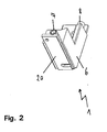
- FIG. 2 is a perspective view of the first embodiment of a corner drive 1 is shown.
- the housing 6 has attachment surfaces 20, via which it can be fastened to a wing or a fixed enclosure.
- the coupling elements 7, 8 have an inner contour, which is formed in the embodiment as a hexagon socket. For assembly, these coupling elements 7, 8 are moved into the housing 6 and then pushed onto a rotary member having an external hexagon.
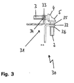
- FIG. 3 an alternative embodiment of a corner drive 30 is shown.
- the corner drive 30 has a bearing device 31, wherein a bearing 32, 33 is provided for each connection piece 2, 3.
- the connecting pieces 2, 3 are rotatably connected to a bevel gear 4, 5.
- the connecting pieces 2, 3 have Lageräbête 34, with which they are mounted in the bearings 32, 33.
- the bearings 32, 33 are formed as bearing holes.
- On both sides of the bearing section 34 circumferential webs 35, 36 are formed, so that the connecting pieces 2, 3 are immovable in the axial direction.
- the connecting pieces 2, 3 can either be coupled via a coupling element with a rotary element or they can be plugged directly into a corresponding rotary element, wherein the rotary element has a receptacle whose inner contour is adapted to the outer contour of the connecting pieces 2, 3.
- a perspective view of the corner 30 is shown.
- the bearing device 31 has attachment openings 37, so that the corner drive 30 can be attached to a wing or a fixed enclosure.
- the bearing device 31 has a slotted bearing hole for each connecting piece 2, 3 or for each bearing section of a connecting piece 2, 3. In this slotted bearing hole of the bearing portion 34 can be introduced only in an assembly position. In use, the corner drive 30 takes the bearing section 34 no longer its mounting position and is therefore not removable from the bearing hole.
Landscapes
- Engineering & Computer Science (AREA)
- Mechanical Engineering (AREA)
- Civil Engineering (AREA)
- Structural Engineering (AREA)
- Hinges (AREA)
- Joining Of Corner Units Of Frames Or Wings (AREA)
- Power-Operated Mechanisms For Wings (AREA)
- Pivots And Pivotal Connections (AREA)
Claims (9)
- Renvoi d'angle (1, 30) pour coupler les mouvements d'au moins deux éléments de rotation (13) d'un système d'armature d'un châssis fixe d'une fenêtre, d'une porte ou d'un objet similaire comportant un battant apte à l'ouverture et à la fermeture, lesdits éléments pouvant tourner, et s'étendant respectivement le long d'un côté dans la direction périphérique de la feuillure, ledit renvoi d'angle (1, 30) comprenant deux pièces de rattachement (2, 3), caractérisé par le fait qu'un élément respectif d'accouplement (7, 8) repose par concordance de formes, dans une position d'utilisation, sur une pièce de rattachement (2, 3) et sur un élément de rotation (13), et instaure un accouplement à verrouillage rotatif entre ladite pièce de rattachement (2, 3) et l'élément de rotation (13), considéré, ledit élément d'accouplement (7, 8) étant monté coulissant sur la pièce de rattachement, en opposition à une force de rappel.
- Renvoi d'angle (1, 30) selon la revendication 1, caractérisé par le fait que l'élément d'accouplement (7, 8) est réalisé sous la forme d'une douille dont le profil intérieur correspond au profil extérieur de la pièce de rattachement (2, 3) et de l'élément de rotation (13).
- Renvoi d'angle selon l'une des revendications précédentes, caractérisé par le fait qu'un boîtier (6) est prévu pour ledit renvoi d'angle (1, 30) et l'élément d'accouplement (7, 8) est en appui contre ledit boîtier (6) dans une position d'utilisation, par une extrémité.
- Renvoi d'angle selon l'une des revendications précédentes, caractérisé par le fait que l'élément de rotation (13) est réalisé sous la forme d'un élément de verrouillage, d'une tige d'entraînement ou d'une pièce d'accouplement.
- Renvoi d'angle selon l'une des revendications précédentes ou selon le préambule de la revendication 1, caractérisé par la présence d'un système de montage (31) affecté aux pièces de rattachement (2, 3), et dans lequel lesdites pièces de rattachement (2, 3) sont logées par une zone de portée (34), lesdites pièces de rattachement (2, 3) pouvant être insérées dans ledit système de montage (31) dans une position de montage, et étant logées dans ledit système de montage (31), de manière imperdable, dans une position d'utilisation.
- Renvoi d'angle selon l'une des revendications précédentes, caractérisé par le fait que le système de montage (31) offre un trou de montage (40) pourvu d'une fente et assigné à chaque pièce de rattachement (2, 3), une première cote des zones de montage étant adaptée à la largeur (b) de la fente, et une seconde cote desdites zones étant adaptée au diamètre dudit trou de montage.
- Renvoi d'angle selon l'une des revendications précédentes, caractérisé par le fait que ledit renvoi d'angle (1, 30) est réalisé sous la forme d'un système de renvoi à roues coniques.
- Renvoi d'angle selon l'une des revendications précédentes, caractérisé par le fait que les pièces de rattachement (2, 3) peuvent être respectivement emboîtées dans un logement pratiqué à la face frontale d'un élément de verrouillage ou d'une tige d'entraînement, et adapté au profil extérieur desdites pièces de rattachement (2, 3).
- Fenêtre, porte ou objet similaire comportant un battant apte à l'ouverture et à la fermeture, ainsi qu'un châssis fixe, avec un système d'armature comptant au moins deux éléments de rotation (13) pouvant tourner, sachant que lesdits éléments de rotation (13) s'étendent respectivement le long d'un côté de la fenêtre, de la porte ou de l'objet similaire, dans la direction périphérique de la feuillure, et que les mouvements desdits éléments sont couplés par l'intermédiaire d'un renvoi d'angle (1, 30) selon l'une des revendications précédentes.
Applications Claiming Priority (1)
| Application Number | Priority Date | Filing Date | Title |
|---|---|---|---|
| DE102004056042A DE102004056042A1 (de) | 2004-11-19 | 2004-11-19 | Fenster, Tür oder dergleichen mit einer Eckumlenkung |
Publications (2)
| Publication Number | Publication Date |
|---|---|
| EP1659250A1 EP1659250A1 (fr) | 2006-05-24 |
| EP1659250B1 true EP1659250B1 (fr) | 2009-07-01 |
Family
ID=35850084
Family Applications (1)
| Application Number | Title | Priority Date | Filing Date |
|---|---|---|---|
| EP05022563A Expired - Lifetime EP1659250B1 (fr) | 2004-11-19 | 2005-10-17 | Fenêtre, porte ou analogue avec un renvoi de coin |
Country Status (3)
| Country | Link |
|---|---|
| EP (1) | EP1659250B1 (fr) |
| AT (1) | ATE435356T1 (fr) |
| DE (2) | DE102004056042A1 (fr) |
Cited By (1)
| Publication number | Priority date | Publication date | Assignee | Title |
|---|---|---|---|---|
| US12264506B2 (en) * | 2020-10-09 | 2025-04-01 | Assa Abloy Access And Egress Hardware Group, Inc. | Exit device rod adjustment |
Families Citing this family (5)
| Publication number | Priority date | Publication date | Assignee | Title |
|---|---|---|---|---|
| JP5927208B2 (ja) | 2011-02-25 | 2016-06-01 | シー イー エス コントロール エンクロージャー システムズ ゲーエムベーハー | 中空区画のためのシーリング要素及びシーリング・システム |
| RU2577521C2 (ru) | 2011-02-25 | 2016-03-20 | С Е С Контрол Энкложе Системз Гмбх | Способ изготовления прямоугольных или квадратных стеновых элементов из листового материала и стеновой элемент, полученный таким способом |
| JP2014510882A (ja) | 2011-02-25 | 2014-05-01 | シー イー エス コントロール エンクロージャー システムズ ゲーエムベーハー | 中空プロフィールのためのコーナーコネクター |
| WO2012113550A1 (fr) * | 2011-02-25 | 2012-08-30 | C E S Control Enclosure Systems Gmbh | Ensemble porte à fermeture magnétique |
| DE102012011011B4 (de) * | 2012-06-02 | 2014-12-04 | Roto Frank Ag | Beschlagsystem für ein Fenster, eine Tür oder dergleichen |
Family Cites Families (9)
| Publication number | Priority date | Publication date | Assignee | Title |
|---|---|---|---|---|
| GB191128755A (en) * | 1911-12-20 | 1912-02-15 | George Albert Chaddock | Improvements in and relating to Windows. |
| US1033057A (en) * | 1912-02-08 | 1912-07-16 | American Hardware Corp | Adjusting mechanism for door-bolts. |
| US3145021A (en) * | 1961-09-21 | 1964-08-18 | Wilmot Castle Co | Door locking apparatus |
| DE1242121B (de) * | 1963-08-01 | 1967-06-08 | Udo Eyers | Fuer Fenster, Tueren od. dgl. bestimmter Zentralverschluss mit durch Eckumlenkungen miteinander verbundenen Verschluss- und Abdichtschienen |
| FR1402698A (fr) * | 1964-08-01 | 1965-06-11 | Testa Ets | Fermeture centrale pour fenêtre |
| NL7502311A (nl) * | 1975-02-27 | 1976-08-31 | Martens Brandkasten Bv | Sluiting voor kluisdeur of dergelijke. |
| DE3920239A1 (de) * | 1989-06-21 | 1991-01-03 | Geze Gmbh & Co | Getriebe fuer ein betaetigungsgestaenge einer ausstellvorrichtung eines fensters |
| EP0505887A1 (fr) * | 1991-03-27 | 1992-09-30 | Siemens Aktiengesellschaft | Dispositif de verrouillage pour une porte de sécurité |
| US5165740A (en) * | 1992-01-17 | 1992-11-24 | White Welding And Mfg., Inc. | Anti-racking means and method for cargo container doors |
-
2004
- 2004-11-19 DE DE102004056042A patent/DE102004056042A1/de not_active Ceased
-
2005
- 2005-10-17 EP EP05022563A patent/EP1659250B1/fr not_active Expired - Lifetime
- 2005-10-17 AT AT05022563T patent/ATE435356T1/de active
- 2005-10-17 DE DE502005007609T patent/DE502005007609D1/de not_active Expired - Lifetime
Cited By (1)
| Publication number | Priority date | Publication date | Assignee | Title |
|---|---|---|---|---|
| US12264506B2 (en) * | 2020-10-09 | 2025-04-01 | Assa Abloy Access And Egress Hardware Group, Inc. | Exit device rod adjustment |
Also Published As
| Publication number | Publication date |
|---|---|
| DE502005007609D1 (de) | 2009-08-13 |
| DE102004056042A1 (de) | 2006-06-01 |
| EP1659250A1 (fr) | 2006-05-24 |
| ATE435356T1 (de) | 2009-07-15 |
Similar Documents
| Publication | Publication Date | Title |
|---|---|---|
| DE3943715C2 (de) | Drehstangenverschluß | |
| EP2961899B1 (fr) | Poignée de commande | |
| WO2001092667A1 (fr) | Serrure a barres pour systeme de fermeture | |
| DE9409285U1 (de) | Scharnierstiftloses wartungsfrei gelagertes Blechscharnier für Kraftwagentüren | |
| DE102017121868B3 (de) | Verriegelungsbügel mit Sperre sowie einem Verfahren zur Verriegelung und Entriegelung einer Steckverbindung | |
| EP3277899B1 (fr) | Système de poignée de porte d'un véhicule automobile | |
| DE202005021315U1 (de) | Kupplungseinrichtung mit einer Panikfunktion für elektromechanische Feststellvorrichtungen | |
| EP1659250B1 (fr) | Fenêtre, porte ou analogue avec un renvoi de coin | |
| EP2949842B1 (fr) | Système de poignée de porte pour un véhicule | |
| DE69920789T3 (de) | Anordnung für die Bewegungsübertragung zwischen einem Riegel und einem Kraftfahrzeugschloss | |
| EP1862613A1 (fr) | Dispositif d'actionnement de fenêtres | |
| EP3498941A1 (fr) | Élément d'actionnement pourvu d'un dispositif de verrouillage | |
| EP2642054A2 (fr) | Penture pour un agencement couvert entre un cadre de porte et un vantail | |
| DE60200336T2 (de) | Kastenverschlussvorrichtung | |
| WO2020249165A1 (fr) | Ensemble de leviers pour des applications en technique automobile | |
| EP4045744B1 (fr) | Ensemble ferrure | |
| WO2006125535A1 (fr) | Gond a charniere et charniere | |
| EP3741935B1 (fr) | Verrou d'aiguille à articulation | |
| EP2801684B1 (fr) | Système modulaire d'engrenage | |
| EP2532816B1 (fr) | Dispositif d'entraînement pour une armature de bielle | |
| DE102019209382A1 (de) | Gehäuse für einen Antrieb und Antrieb | |
| DE19717116B4 (de) | Drehlager | |
| DE102023122595A1 (de) | Antriebseinheit | |
| DE4230476A1 (de) | Fenster- oder Türbeschlag | |
| DE9207893U1 (de) | Aufsatzgetriebe eines Fenster- oder Türbeschlages |
Legal Events
| Date | Code | Title | Description |
|---|---|---|---|
| PUAI | Public reference made under article 153(3) epc to a published international application that has entered the european phase |
Free format text: ORIGINAL CODE: 0009012 |
|
| AK | Designated contracting states |
Kind code of ref document: A1 Designated state(s): AT BE BG CH CY CZ DE DK EE ES FI FR GB GR HU IE IS IT LI LT LU LV MC NL PL PT RO SE SI SK TR |
|
| AX | Request for extension of the european patent |
Extension state: AL BA HR MK YU |
|
| 17P | Request for examination filed |
Effective date: 20061121 |
|
| AKX | Designation fees paid |
Designated state(s): AT CH DE FR LI |
|
| GRAP | Despatch of communication of intention to grant a patent |
Free format text: ORIGINAL CODE: EPIDOSNIGR1 |
|
| GRAS | Grant fee paid |
Free format text: ORIGINAL CODE: EPIDOSNIGR3 |
|
| GRAA | (expected) grant |
Free format text: ORIGINAL CODE: 0009210 |
|
| AK | Designated contracting states |
Kind code of ref document: B1 Designated state(s): AT CH DE FR LI |
|
| REG | Reference to a national code |
Ref country code: CH Ref legal event code: EP |
|
| REF | Corresponds to: |
Ref document number: 502005007609 Country of ref document: DE Date of ref document: 20090813 Kind code of ref document: P |
|
| PLBE | No opposition filed within time limit |
Free format text: ORIGINAL CODE: 0009261 |
|
| STAA | Information on the status of an ep patent application or granted ep patent |
Free format text: STATUS: NO OPPOSITION FILED WITHIN TIME LIMIT |
|
| 26N | No opposition filed |
Effective date: 20100406 |
|
| REG | Reference to a national code |
Ref country code: FR Ref legal event code: PLFP Year of fee payment: 11 |
|
| PGFP | Annual fee paid to national office [announced via postgrant information from national office to epo] |
Ref country code: CH Payment date: 20151026 Year of fee payment: 11 |
|
| PGFP | Annual fee paid to national office [announced via postgrant information from national office to epo] |
Ref country code: FR Payment date: 20151026 Year of fee payment: 11 Ref country code: AT Payment date: 20151022 Year of fee payment: 11 |
|
| PGFP | Annual fee paid to national office [announced via postgrant information from national office to epo] |
Ref country code: DE Payment date: 20161028 Year of fee payment: 12 |
|
| REG | Reference to a national code |
Ref country code: CH Ref legal event code: PL |
|
| REG | Reference to a national code |
Ref country code: AT Ref legal event code: MM01 Ref document number: 435356 Country of ref document: AT Kind code of ref document: T Effective date: 20161017 |
|
| REG | Reference to a national code |
Ref country code: FR Ref legal event code: ST Effective date: 20170630 |
|
| PG25 | Lapsed in a contracting state [announced via postgrant information from national office to epo] |
Ref country code: CH Free format text: LAPSE BECAUSE OF NON-PAYMENT OF DUE FEES Effective date: 20161031 Ref country code: LI Free format text: LAPSE BECAUSE OF NON-PAYMENT OF DUE FEES Effective date: 20161031 Ref country code: FR Free format text: LAPSE BECAUSE OF NON-PAYMENT OF DUE FEES Effective date: 20161102 |
|
| PG25 | Lapsed in a contracting state [announced via postgrant information from national office to epo] |
Ref country code: AT Free format text: LAPSE BECAUSE OF NON-PAYMENT OF DUE FEES Effective date: 20161017 |
|
| REG | Reference to a national code |
Ref country code: DE Ref legal event code: R119 Ref document number: 502005007609 Country of ref document: DE |
|
| PG25 | Lapsed in a contracting state [announced via postgrant information from national office to epo] |
Ref country code: DE Free format text: LAPSE BECAUSE OF NON-PAYMENT OF DUE FEES Effective date: 20180501 |