EP1659356A2 - Réfrigérateur et/ou congélateur - Google Patents
Réfrigérateur et/ou congélateur Download PDFInfo
- Publication number
- EP1659356A2 EP1659356A2 EP05025162A EP05025162A EP1659356A2 EP 1659356 A2 EP1659356 A2 EP 1659356A2 EP 05025162 A EP05025162 A EP 05025162A EP 05025162 A EP05025162 A EP 05025162A EP 1659356 A2 EP1659356 A2 EP 1659356A2
- Authority
- EP
- European Patent Office
- Prior art keywords
- interior
- connecting line
- ambient atmosphere
- freezer
- refrigerator
- Prior art date
- Legal status (The legal status is an assumption and is not a legal conclusion. Google has not performed a legal analysis and makes no representation as to the accuracy of the status listed.)
- Granted
Links
- 238000007710 freezing Methods 0.000 title claims 7
- 230000008014 freezing Effects 0.000 title claims 7
- 238000010438 heat treatment Methods 0.000 claims abstract description 36
- 239000002274 desiccant Substances 0.000 claims abstract description 23
- 238000001816 cooling Methods 0.000 claims abstract description 5
- 238000005057 refrigeration Methods 0.000 claims description 5
- 238000001035 drying Methods 0.000 claims 3
- 239000003570 air Substances 0.000 description 25
- 230000015572 biosynthetic process Effects 0.000 description 4
- 238000004891 communication Methods 0.000 description 3
- 230000001419 dependent effect Effects 0.000 description 2
- 230000001172 regenerating effect Effects 0.000 description 2
- 239000012080 ambient air Substances 0.000 description 1
- 230000000694 effects Effects 0.000 description 1
- 238000005259 measurement Methods 0.000 description 1
- 238000000034 method Methods 0.000 description 1
- 239000002808 molecular sieve Substances 0.000 description 1
- 230000008929 regeneration Effects 0.000 description 1
- 238000011069 regeneration method Methods 0.000 description 1
- URGAHOPLAPQHLN-UHFFFAOYSA-N sodium aluminosilicate Chemical compound [Na+].[Al+3].[O-][Si]([O-])=O.[O-][Si]([O-])=O URGAHOPLAPQHLN-UHFFFAOYSA-N 0.000 description 1
- 230000032258 transport Effects 0.000 description 1
Images


Classifications
-
- F—MECHANICAL ENGINEERING; LIGHTING; HEATING; WEAPONS; BLASTING
- F25—REFRIGERATION OR COOLING; COMBINED HEATING AND REFRIGERATION SYSTEMS; HEAT PUMP SYSTEMS; MANUFACTURE OR STORAGE OF ICE; LIQUEFACTION SOLIDIFICATION OF GASES
- F25D—REFRIGERATORS; COLD ROOMS; ICE-BOXES; COOLING OR FREEZING APPARATUS NOT OTHERWISE PROVIDED FOR
- F25D21/00—Defrosting; Preventing frosting; Removing condensed or defrost water
- F25D21/04—Preventing the formation of frost or condensate
-
- F—MECHANICAL ENGINEERING; LIGHTING; HEATING; WEAPONS; BLASTING
- F25—REFRIGERATION OR COOLING; COMBINED HEATING AND REFRIGERATION SYSTEMS; HEAT PUMP SYSTEMS; MANUFACTURE OR STORAGE OF ICE; LIQUEFACTION SOLIDIFICATION OF GASES
- F25D—REFRIGERATORS; COLD ROOMS; ICE-BOXES; COOLING OR FREEZING APPARATUS NOT OTHERWISE PROVIDED FOR
- F25D17/00—Arrangements for circulating cooling fluids; Arrangements for circulating gas, e.g. air, within refrigerated spaces
- F25D17/04—Arrangements for circulating cooling fluids; Arrangements for circulating gas, e.g. air, within refrigerated spaces for circulating air, e.g. by convection
- F25D17/042—Air treating means within refrigerated spaces
-
- F—MECHANICAL ENGINEERING; LIGHTING; HEATING; WEAPONS; BLASTING
- F25—REFRIGERATION OR COOLING; COMBINED HEATING AND REFRIGERATION SYSTEMS; HEAT PUMP SYSTEMS; MANUFACTURE OR STORAGE OF ICE; LIQUEFACTION SOLIDIFICATION OF GASES
- F25D—REFRIGERATORS; COLD ROOMS; ICE-BOXES; COOLING OR FREEZING APPARATUS NOT OTHERWISE PROVIDED FOR
- F25D2317/00—Details or arrangements for circulating cooling fluids; Details or arrangements for circulating gas, e.g. air, within refrigerated spaces, not provided for in other groups of this subclass
- F25D2317/04—Treating air flowing to refrigeration compartments
- F25D2317/041—Treating air flowing to refrigeration compartments by purification
- F25D2317/0411—Treating air flowing to refrigeration compartments by purification by dehumidification
Definitions
- the invention relates to a refrigerator and / or freezer with a coolable by means of a refrigeration device interior for receiving the goods to be cooled, which is closed by a door or flap, wherein the interior communicates via at least one connecting line with the ambient atmosphere and wherein a in The connecting line arranged desiccant is provided by means of which the air flowing into the interior of the air moisture is removed.
- a refrigerator and / or freezer is known, for example, from EP 0 805 321 B1.
- the interior of the device is connected via a arranged in the door or flap of the device connecting line with the ambient atmosphere in connection.
- the connecting line there is a regenerable desiccant, by means of which the air flowing in via the connecting line into the interior air moisture is extracted.
- the regeneration of the drying agent takes place in that the cold dry air flowing out of the interior during the compressor standstill flows through the desiccant, thereby absorbing moisture and thus regenerating the desiccant.
- the regenerable drying agent serves to keep the moisture content in the interior of the refrigerator or freezer low and thus counteract the risk of icing.
- a further disadvantage is that humid air is sucked into the interior in the case of a connecting line blocked by icing through the finest leaks during the cooling process, which leads to the device beginning to freeze strongly.
- This object is achieved on the basis of a refrigerator and / or freezer of the type mentioned above in that the section of the connecting line located between the interior and the desiccant and / or between the desiccant and the ambient atmosphere is provided with a heating device.
- a heating device In this way it is possible to heat the corresponding sections of the connecting line, whereby the ice formation can be effectively prevented or reduced and ensures the exchange of air even at high humidity and / or many openings of the door or flap of the device is.
- the heating device may be designed such that it is operated permanently or intermittently. The exact adjustment of the parameters of the heater can be chosen so that icing does not or not to the extent that the air exchange over the said connection line is substantially hindered.
- the design of the heater is essentially arbitrary. It is conceivable, for example, that the heating device is designed as a resistance heating element.
- the located between the interior and the desiccant section of the connecting line is designed as a corrugated hose. In a preferred embodiment of the invention, this opens into an opening in the interior of the refrigerator or freezer and is used to supply air or discharge into and out of the interior.
- the present invention can also be realized with two or more than two connecting lines, via which the interior of the refrigerator and / or freezer communicates with the ambient atmosphere, wherein preferably each of the connecting lines is provided with a heating device. It is also conceivable, not all, but only one or some of the connecting lines to perform with a heater, so that under extreme conditions, d. H. high humidity or frequent opening of the device at least these lines are available for air exchange.
- the door, flap or the inner container of the device is provided with an opening into which the connecting line opens. It is also possible to provide the opening at any other location of the refrigerator or even several such openings.
- the door or flap has an inner lid adjacent to the refrigerator compartment and an outer lid communicating with the ambient atmosphere, wherein the inner lid has an opening into which open the connecting line or connecting lines and wherein the connecting line and the heating device between the inner and outer lid are arranged.
- the desiccant may be received in a dryer cartridge having an opening in an end region over which the dryer cartridge communicates with the ambient atmosphere.
- the dryer cartridge communicates in its other end with the above-mentioned corrugated hose or with any other conduit in connection, leading to the interior of the device.
- the dryer cartridge it is also possible for the dryer cartridge to be connected in its two end regions to further sections of the connecting line or further corrugated tubes, one of which opens into the interior space and the other into the ambient atmosphere.
- the heating device can be arranged such that it heats the connecting lines or corrugated tubes over their entire length or only in sections.
- the desiccant is arranged such that it is regenerated exclusively by the cold, dry air flowing out of the interior of the refrigerator and / or freezer into the ambient atmosphere during the standstill of the compressor. This air absorbs moisture from the desiccant and transports it to the ambient atmosphere, thereby regenerating the desiccant.
- FIG. 1 shows a perspective view of a partial region of the inner lid 12 which forms the region of the flap or the lid of a freezer adjacent to the refrigerator compartment.
- the opening 16 through which dry air flows out of the interior of the device when the compressor of the refrigeration device of the device and when operating befindlichem compressor by means of the drying agent dehumidified air flows from the environment into the interior.
- the two marked in Figure 1 oval areas indicate the sections in which are located in the area behind the inner lid 12 arranged heated corrugated tubes, the arrangement of which shows in detail from Figure 5.
- the said corrugated hoses are heated by means of a suitable heating device in order to prevent ice formation in the corrugated hoses or to reduce them to a level which allows an exchange of air between the interior of the device and the ambient atmosphere.
- the heater can be designed arbitrarily.
- the resistance heating element 32 shown in FIG. 2 can be used, which can be wound in a suitable manner around the connection line or the corrugated tube or can be guided along it in order to effect the required heating. In his End regions, the resistance heating element 32 has two contacts for electrical supply.
- the heating device according to the invention can be operated continuously or intermittently.
- the operation of the heater is essentially to be dimensioned so that the formation of ice in the affected areas of the connecting tube is prevented or reduced to a level that allows the exchange of air between the interior and ambient atmosphere in the desired manner.
- FIG. 3 shows a view of the corrugated hose 22 whose end 24 shown on the left is connected to the inner cover 12 of the flap of the device such that it opens into the opening 16 according to FIG. 1 or is in communication therewith.
- the illustrated on the right end 23 is connected to the apparent from Figure 5 dryer cartridge.
- the resistance heating element 32 is guided and fastened thereto in a suitable manner so that the desired heating of the corrugated hose 22 takes place when the current flows through the heating element 32.
- FIG. 4 shows a thermographic image of the arrangement according to FIG. 3 and illustrates that the resistance heating element 32 in the current-carrying state leads to the desired heating of the corrugated tube 22.
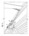
- Figure 5 shows a perspective view of the adjacent to the interior of the device inner lid 12 and adjacent to the ambient atmosphere outer cover 14, which together form the flap of the device.
- a corresponding design is of course also possible with a door of a refrigerator or freezer.
- FIG. 5 illustrates that two connecting lines 20, 20 'are arranged in the area between the inner lid 12 and the outer lid 14, and these are shown in FIG Corrugated hoses 22, 22 'include, which in turn are provided with heaters 30, 30'.
- the corrugated hoses 22, 22' are in communication with dryer cartridges 40, 40 ', which are also part of the connecting lines according to the invention.
- the dry cold air flows due to its expansion through the opening 16 in the corrugated hoses 22, 22 'and then in the dryer cartridges 40, 40'.
- the dry air absorbs moisture from the desiccant, which regenerates it. The moisture is transported in this way to the outside in the ambient atmosphere.
- the heaters 30, 30 ' cause the formation of ice in the corrugated tubes 22, 22' is prevented or prevented so far that an exchange of air between the interior of the device and ambient atmosphere remains ensured.
- connection line it is not absolutely necessary to heat the entire connection line. For example, it is possible to heat only a portion of the connecting line, in which without heating usually with an increased incidence of ice is to be expected. As can be seen from the exemplary embodiment according to FIG. 5, it may be sufficient to heat the part of the connecting lines which adjoins the opening 16 to the interior of the device and to provide no heating device in the area adjoining the dryer cartridges.
- said heating means it is possible to operate said heating means continuously or intermittently. In the latter case, it may be provided to provide constant periods without heating between heating periods or to make the heating also dependent on certain parameters, such as, for example, the humidity, the pressure drop across the connecting line or the frequency of the openings of the refrigerator or freezer.
- the measurement of the pressure drop in the connecting line or in sections of the connecting line can also be used to determine whether or to what extent the connecting line is permeable or blocked. It would be necessary to provide a control device which makes the heating power or heating times dependent on the parameters mentioned.
Landscapes
- Engineering & Computer Science (AREA)
- Chemical & Material Sciences (AREA)
- Combustion & Propulsion (AREA)
- Physics & Mathematics (AREA)
- Mechanical Engineering (AREA)
- Thermal Sciences (AREA)
- General Engineering & Computer Science (AREA)
- Cold Air Circulating Systems And Constructional Details In Refrigerators (AREA)
- Devices That Are Associated With Refrigeration Equipment (AREA)
- Drying Of Solid Materials (AREA)
Applications Claiming Priority (1)
| Application Number | Priority Date | Filing Date | Title |
|---|---|---|---|
| DE202004017836U DE202004017836U1 (de) | 2004-11-17 | 2004-11-17 | Kühl- und/oder Gefriergerät |
Publications (3)
| Publication Number | Publication Date |
|---|---|
| EP1659356A2 true EP1659356A2 (fr) | 2006-05-24 |
| EP1659356A3 EP1659356A3 (fr) | 2009-03-04 |
| EP1659356B1 EP1659356B1 (fr) | 2011-08-17 |
Family
ID=35841981
Family Applications (1)
| Application Number | Title | Priority Date | Filing Date |
|---|---|---|---|
| EP05025162A Expired - Lifetime EP1659356B1 (fr) | 2004-11-17 | 2005-11-17 | Réfrigérateur et/ou congélateur |
Country Status (4)
| Country | Link |
|---|---|
| EP (1) | EP1659356B1 (fr) |
| AT (1) | ATE520936T1 (fr) |
| DE (1) | DE202004017836U1 (fr) |
| ES (1) | ES2368433T3 (fr) |
Citations (1)
| Publication number | Priority date | Publication date | Assignee | Title |
|---|---|---|---|---|
| EP0805321B1 (fr) | 1996-05-03 | 2001-12-05 | LIEBHERR-WERK LIENZ GES. mbH | Appareil de réfrigération et/ou de congélation |
Family Cites Families (3)
| Publication number | Priority date | Publication date | Assignee | Title |
|---|---|---|---|---|
| US2604760A (en) * | 1950-04-29 | 1952-07-29 | Gen Electric | Moisture collecting and removing arrangement |
| US4911739A (en) * | 1989-07-07 | 1990-03-27 | Multiform Desiccants, Inc. | Self-retaining adsorbent cartridge for refrigerant receiver |
| DE19957807A1 (de) * | 1999-12-01 | 2001-06-07 | Bsh Bosch Siemens Hausgeraete | Kältegerät |
-
2004
- 2004-11-17 DE DE202004017836U patent/DE202004017836U1/de not_active Expired - Lifetime
-
2005
- 2005-11-17 EP EP05025162A patent/EP1659356B1/fr not_active Expired - Lifetime
- 2005-11-17 AT AT05025162T patent/ATE520936T1/de active
- 2005-11-17 ES ES05025162T patent/ES2368433T3/es not_active Expired - Lifetime
Patent Citations (1)
| Publication number | Priority date | Publication date | Assignee | Title |
|---|---|---|---|---|
| EP0805321B1 (fr) | 1996-05-03 | 2001-12-05 | LIEBHERR-WERK LIENZ GES. mbH | Appareil de réfrigération et/ou de congélation |
Also Published As
| Publication number | Publication date |
|---|---|
| ATE520936T1 (de) | 2011-09-15 |
| ES2368433T3 (es) | 2011-11-17 |
| DE202004017836U1 (de) | 2006-03-23 |
| EP1659356A3 (fr) | 2009-03-04 |
| EP1659356B1 (fr) | 2011-08-17 |
Similar Documents
| Publication | Publication Date | Title |
|---|---|---|
| AT413080B (de) | Trocknungsvorrichtung | |
| DE4209188C2 (de) | Anordnung zur Klimatisierung von Räumen, insbesondere der Fahrgastzelle von Kraftfahrzeugen | |
| DE69813373T2 (de) | Kühlschrank mit einer vor Eisbildung schützenden Vorrichtung | |
| DE102008029922B4 (de) | Raumlufttechnisches Gerät | |
| DE2149548B2 (de) | Klimaanlage für Eisenbahnfahrzeuge | |
| CH626155A5 (fr) | ||
| DE102011083614A1 (de) | Trocknerschaltung für eine pneumatische Regelvorrichtung eines Fahrzeugs | |
| DE69507533T2 (de) | Klimaanlage mit Wärmepumpe | |
| DE2726560C2 (de) | Abtauvorrichtung für eine Kühl- oder Tiefkühlvitrine | |
| DE202011110325U1 (de) | Luftentfeuchtungseinheit | |
| DE19823796C1 (de) | Heizungs- oder Klimaanlage für Fahrzeuge | |
| DE19955253B4 (de) | Filtervorrichtung | |
| EP2313720A1 (fr) | Moyen de fermeture d'un canal d'eau de décongélation d'un réfrigérateur, canal d'eau de décongélation d'un réfrigérateur et réfrigérateur | |
| EP1659356B1 (fr) | Réfrigérateur et/ou congélateur | |
| DE102013207566A1 (de) | Vorrichtung und Verfahren zum Trocknen von Luft sowie Schienenfahrzeug mit einer derartigen Vorrichtung | |
| EP0789206A2 (fr) | Appareil frigorifique | |
| EP1560722B1 (fr) | Dispositif d'aeration pour un vehicule automoblie comprenant un evaporateur presentant une fonction d'accumulation | |
| DE19954555C2 (de) | Vorrichtung und Verfahren zur Belüftung eines Raumes mit Wärmerückgewinnung | |
| DE2502072B2 (de) | Anlage zur Behandlung von Luft für Räume | |
| DE19807341C2 (de) | Verfahren zum Betreiben einer Fahrzeug-Klimaanlage | |
| WO2025021530A1 (fr) | Unité d'alimentation en air comprimé, système d'alimentation en air comprimé, véhicule et procédé de fonctionnement | |
| DE3314056C2 (fr) | ||
| DE102015224123A1 (de) | Klimatisierungsvorrichtung für ein Kraftfahrzeug und Verfahren zu deren Betrieb | |
| DE3219450C2 (fr) | ||
| DE102009017765A1 (de) | Kühl- und/oder Gefriergerät |
Legal Events
| Date | Code | Title | Description |
|---|---|---|---|
| PUAI | Public reference made under article 153(3) epc to a published international application that has entered the european phase |
Free format text: ORIGINAL CODE: 0009012 |
|
| AK | Designated contracting states |
Kind code of ref document: A2 Designated state(s): AT BE BG CH CY CZ DE DK EE ES FI FR GB GR HU IE IS IT LI LT LU LV MC NL PL PT RO SE SI SK TR |
|
| AX | Request for extension of the european patent |
Extension state: AL BA HR MK YU |
|
| PUAL | Search report despatched |
Free format text: ORIGINAL CODE: 0009013 |
|
| AK | Designated contracting states |
Kind code of ref document: A3 Designated state(s): AT BE BG CH CY CZ DE DK EE ES FI FR GB GR HU IE IS IT LI LT LU LV MC NL PL PT RO SE SI SK TR |
|
| AX | Request for extension of the european patent |
Extension state: AL BA HR MK YU |
|
| 17Q | First examination report despatched |
Effective date: 20090930 |
|
| 17P | Request for examination filed |
Effective date: 20090901 |
|
| AKX | Designation fees paid |
Designated state(s): AT DE ES FR IT |
|
| GRAP | Despatch of communication of intention to grant a patent |
Free format text: ORIGINAL CODE: EPIDOSNIGR1 |
|
| GRAS | Grant fee paid |
Free format text: ORIGINAL CODE: EPIDOSNIGR3 |
|
| GRAA | (expected) grant |
Free format text: ORIGINAL CODE: 0009210 |
|
| AK | Designated contracting states |
Kind code of ref document: B1 Designated state(s): AT DE ES FR IT |
|
| REG | Reference to a national code |
Ref country code: DE Ref legal event code: R096 Ref document number: 502005011768 Country of ref document: DE Effective date: 20111027 |
|
| REG | Reference to a national code |
Ref country code: ES Ref legal event code: FG2A Ref document number: 2368433 Country of ref document: ES Kind code of ref document: T3 Effective date: 20111117 |
|
| PLBE | No opposition filed within time limit |
Free format text: ORIGINAL CODE: 0009261 |
|
| STAA | Information on the status of an ep patent application or granted ep patent |
Free format text: STATUS: NO OPPOSITION FILED WITHIN TIME LIMIT |
|
| 26N | No opposition filed |
Effective date: 20120521 |
|
| REG | Reference to a national code |
Ref country code: DE Ref legal event code: R097 Ref document number: 502005011768 Country of ref document: DE Effective date: 20120521 |
|
| REG | Reference to a national code |
Ref country code: AT Ref legal event code: MM01 Ref document number: 520936 Country of ref document: AT Kind code of ref document: T Effective date: 20111117 |
|
| PG25 | Lapsed in a contracting state [announced via postgrant information from national office to epo] |
Ref country code: AT Free format text: LAPSE BECAUSE OF NON-PAYMENT OF DUE FEES Effective date: 20111117 |
|
| REG | Reference to a national code |
Ref country code: FR Ref legal event code: PLFP Year of fee payment: 11 |
|
| REG | Reference to a national code |
Ref country code: FR Ref legal event code: PLFP Year of fee payment: 12 |
|
| REG | Reference to a national code |
Ref country code: FR Ref legal event code: PLFP Year of fee payment: 13 |
|
| PGFP | Annual fee paid to national office [announced via postgrant information from national office to epo] |
Ref country code: FR Payment date: 20171124 Year of fee payment: 13 |
|
| PGFP | Annual fee paid to national office [announced via postgrant information from national office to epo] |
Ref country code: IT Payment date: 20171130 Year of fee payment: 13 Ref country code: ES Payment date: 20171215 Year of fee payment: 13 |
|
| PGFP | Annual fee paid to national office [announced via postgrant information from national office to epo] |
Ref country code: DE Payment date: 20181203 Year of fee payment: 14 |
|
| PG25 | Lapsed in a contracting state [announced via postgrant information from national office to epo] |
Ref country code: FR Free format text: LAPSE BECAUSE OF NON-PAYMENT OF DUE FEES Effective date: 20181130 Ref country code: IT Free format text: LAPSE BECAUSE OF NON-PAYMENT OF DUE FEES Effective date: 20181117 |
|
| REG | Reference to a national code |
Ref country code: ES Ref legal event code: FD2A Effective date: 20200103 |
|
| PG25 | Lapsed in a contracting state [announced via postgrant information from national office to epo] |
Ref country code: ES Free format text: LAPSE BECAUSE OF NON-PAYMENT OF DUE FEES Effective date: 20181118 |
|
| REG | Reference to a national code |
Ref country code: DE Ref legal event code: R119 Ref document number: 502005011768 Country of ref document: DE |
|
| PG25 | Lapsed in a contracting state [announced via postgrant information from national office to epo] |
Ref country code: DE Free format text: LAPSE BECAUSE OF NON-PAYMENT OF DUE FEES Effective date: 20200603 |