EP1659372B1 - Verfahren zum Auswerten von mittels eines Differenzialtransformators oder einer induktiven Halbbrücke durchgeführten Längenmessungen - Google Patents
Verfahren zum Auswerten von mittels eines Differenzialtransformators oder einer induktiven Halbbrücke durchgeführten Längenmessungen Download PDFInfo
- Publication number
- EP1659372B1 EP1659372B1 EP05025118A EP05025118A EP1659372B1 EP 1659372 B1 EP1659372 B1 EP 1659372B1 EP 05025118 A EP05025118 A EP 05025118A EP 05025118 A EP05025118 A EP 05025118A EP 1659372 B1 EP1659372 B1 EP 1659372B1
- Authority
- EP
- European Patent Office
- Prior art keywords
- voltage
- secondary coil
- period
- voltage levels
- sinusoidal
- Prior art date
- Legal status (The legal status is an assumption and is not a legal conclusion. Google has not performed a legal analysis and makes no representation as to the accuracy of the status listed.)
- Expired - Lifetime
Links
Images

Classifications
-
- G—PHYSICS
- G01—MEASURING; TESTING
- G01D—MEASURING NOT SPECIALLY ADAPTED FOR A SPECIFIC VARIABLE; ARRANGEMENTS FOR MEASURING TWO OR MORE VARIABLES NOT COVERED IN A SINGLE OTHER SUBCLASS; TARIFF METERING APPARATUS; MEASURING OR TESTING NOT OTHERWISE PROVIDED FOR
- G01D5/00—Mechanical means for transferring the output of a sensing member; Means for converting the output of a sensing member to another variable where the form or nature of the sensing member does not constrain the means for converting; Transducers not specially adapted for a specific variable
- G01D5/12—Mechanical means for transferring the output of a sensing member; Means for converting the output of a sensing member to another variable where the form or nature of the sensing member does not constrain the means for converting; Transducers not specially adapted for a specific variable using electric or magnetic means
- G01D5/14—Mechanical means for transferring the output of a sensing member; Means for converting the output of a sensing member to another variable where the form or nature of the sensing member does not constrain the means for converting; Transducers not specially adapted for a specific variable using electric or magnetic means influencing the magnitude of a current or voltage
- G01D5/20—Mechanical means for transferring the output of a sensing member; Means for converting the output of a sensing member to another variable where the form or nature of the sensing member does not constrain the means for converting; Transducers not specially adapted for a specific variable using electric or magnetic means influencing the magnitude of a current or voltage by varying inductance, e.g. by a movable armature
- G01D5/204—Mechanical means for transferring the output of a sensing member; Means for converting the output of a sensing member to another variable where the form or nature of the sensing member does not constrain the means for converting; Transducers not specially adapted for a specific variable using electric or magnetic means influencing the magnitude of a current or voltage by varying inductance, e.g. by a movable armature by influencing the mutual induction between two or more coils
- G01D5/2046—Mechanical means for transferring the output of a sensing member; Means for converting the output of a sensing member to another variable where the form or nature of the sensing member does not constrain the means for converting; Transducers not specially adapted for a specific variable using electric or magnetic means influencing the magnitude of a current or voltage by varying inductance, e.g. by a movable armature by influencing the mutual induction between two or more coils by a movable ferromagnetic element, e.g. a core
-
- G—PHYSICS
- G01—MEASURING; TESTING
- G01D—MEASURING NOT SPECIALLY ADAPTED FOR A SPECIFIC VARIABLE; ARRANGEMENTS FOR MEASURING TWO OR MORE VARIABLES NOT COVERED IN A SINGLE OTHER SUBCLASS; TARIFF METERING APPARATUS; MEASURING OR TESTING NOT OTHERWISE PROVIDED FOR
- G01D5/00—Mechanical means for transferring the output of a sensing member; Means for converting the output of a sensing member to another variable where the form or nature of the sensing member does not constrain the means for converting; Transducers not specially adapted for a specific variable
- G01D5/12—Mechanical means for transferring the output of a sensing member; Means for converting the output of a sensing member to another variable where the form or nature of the sensing member does not constrain the means for converting; Transducers not specially adapted for a specific variable using electric or magnetic means
- G01D5/14—Mechanical means for transferring the output of a sensing member; Means for converting the output of a sensing member to another variable where the form or nature of the sensing member does not constrain the means for converting; Transducers not specially adapted for a specific variable using electric or magnetic means influencing the magnitude of a current or voltage
- G01D5/20—Mechanical means for transferring the output of a sensing member; Means for converting the output of a sensing member to another variable where the form or nature of the sensing member does not constrain the means for converting; Transducers not specially adapted for a specific variable using electric or magnetic means influencing the magnitude of a current or voltage by varying inductance, e.g. by a movable armature
- G01D5/22—Mechanical means for transferring the output of a sensing member; Means for converting the output of a sensing member to another variable where the form or nature of the sensing member does not constrain the means for converting; Transducers not specially adapted for a specific variable using electric or magnetic means influencing the magnitude of a current or voltage by varying inductance, e.g. by a movable armature differentially influencing two coils
- G01D5/2291—Linear or rotary variable differential transformers (LVDTs/RVDTs) having a single primary coil and two secondary coils
Definitions
- the invention is based on a method for evaluating length measurements, which are carried out with a differential transformer or an inductive half-bridge, according to the preamble of claim 1.
- Differential transformers and inductive half-bridges are used, for example, for length measurement in industrial production, quality assurance, process control, robotics, aerospace, the automotive industry and in hydraulic and pneumatic applications. In addition to lengths or distances, these devices can also be used to determine the quantities derivable from distances, such as, for example, the shape of an object.
- the measuring range extends from the nanometer range to the meter range.
- the principle of length measurement is based on the fact that a primary coil fed with a sinusoidal exciter voltage has a magnetically active core with one or two secondary coils is coupled. The primary coil, the secondary coils and the magnetically active core are integrated into a probe.
- the core changes its position during the length measurement, this has an effect on the magnetic coupling between the primary coil and the secondary coils.
- the induced voltage in the secondary coil is linearly dependent on the position of the movable core. The voltage of the secondary coil is therefore a measure of the length.
- the voltage induced at the secondary coil is also sinusoidal. Since a DC voltage signal is desired as the output signal, the voltage induced at the secondary coil is demodulated in the methods known from the prior art. For this purpose, a demodulator is used, which rectifies the AC voltage and forms an RMS value or integration by integration. The rectification and the integration takes place by suitable electrical components. Subsequently, the output signal is digitized by an analog-to-digital converter and forwarded to a computer for further evaluation.
- the voltage of the secondary coil has to be averaged or integrated to determine an output signal over several periods.
- the process is therefore relatively slow.
- the output signal is influenced by the quality of the excitation voltage. Harmonics or an offset reduce the measuring accuracy and lead to a falsification of the output signal.
- the output signal is corrupted by effects that occur during demodulation.
- the method according to the invention with the features of claim 1 has the advantage that the output signal without demodulation of the sinusoidal voltage of the secondary coil is determined. Falsifications or errors that occur during demodulation are thereby eliminated.
- the output signal is derived from the average of at least two voltage values of a period of the sinusoidal voltage of the secondary coil.
- the arithmetic, geometric or harmonic mean value is determined from the amounts of the voltage at at least two times of a period. An offset or harmonics therefore do not distort the output signal or at most to a very small extent.
- the average value is determined to obtain an output signal.
- the method is thus much faster and more accurate than the methods known from the prior art, in which averaged over several periods.
- the output signal is further processed by a computer and often visualized.
- the inventive method makes it possible to connect the inductive probe directly to a computer without the detour via additional electrical components. This procedure is more cost-effective, less subject to measurement errors and also offers the possibility of operating a large number of different probes with the same evaluation hardware.
- the evaluation hardware may be, for example, a PC or PCI card for a computer or a device independent of a computer.
- the maximum and minimum are determined as voltage values of a period of the voltage induced in the secondary coil.
- another advantageous approach is to have two voltage values near the maximum and determine two voltage values near the minimum of one period of the sinusoidal-induced voltage induced in the secondary coil, and to average them out of these four values.
- the voltage values of one period, for example the minimum and the maximum, of the voltage of the secondary coil are digitized before the mean value is determined.
- the mean value can then be determined from the digitized values in a logic module.
- a logic module may be, for example, a Programmable Logic Device, PLD for short.
- the maximum and minimum of a period is also determined to the sinusoidal excitation voltage of the primary coil. Subsequently, first the mean value of the maximum and minimum and finally the quotient of the mean value of the secondary coil and the mean value of the primary coil are formed. The quotient or a value derived from the quotient is output as output signal. By forming the quotient, the voltage drop across the relatively long cable of the probe is eliminated. In addition, noise that affects the excitation voltage and thus the voltage of the secondary coil, eliminated in the output signal. Such disturbances may be, for example, a drift or temperature-induced fluctuations.
- the minimum and maximum of one period of the voltage of the primary coil can be digitized before the average value is determined. From the digitized values, the mean value can then be determined in a logic module and the quotient calculated from the average values of the secondary coil and the primary coil.
- the sinusoidal exciter voltage is generated using a clock generator.
- the same clock is used to specify the times at which the voltage values of a period of the sinusoidal voltage of the secondary coil and possibly the primary coil are measured.
- the excitation voltage on the one hand and the times of measurement of the minima and maxima of the voltage of the secondary coil are synchronized on the other hand. This ensures that the voltage of the secondary coil is determined exactly in the minimum and maximum or near the maximum and minimum. Distortions of the output signal, which are based on a voltage measurement at another time, can be excluded.
- the synchronization also contributes to suppressing the phase difference between the excitation voltage and the voltage of the secondary coil.
- a phase-frequency detection circuit of a phase-locked loop is provided.
- the frequency of the clock for determining the maximum and minimum of a period of the sinusoidal voltage of the secondary coil is an integer multiple of the frequency of the excitation voltage. Frequencies with such relationships to one another are obtained, for example, by dividing a given frequency. This is given for example by a quartz. For this purpose, a programmable dividing device, which is part of the evaluation hardware, are used.
- the complete electronics for an inductive measuring probe with an oscillator, amplifiers, an analog-to-digital converter and a logic module is housed in an evaluation hardware, for example on an industry-standard PCI card. Depending on the model, it has 8 or 16 channels for connecting touch probes. Depending on requirements, more or fewer channels may be provided.
- the computer in which the card is inserted feeds all the primary coils of the measuring probes with the necessary AC voltages.
- the output signal containing the information about the measured length has a resolution of, for example, 16 bits. Higher resolutions are possible.
- the sampling frequencies are between 2 and 50 kilohertz.
- the specific parameters of various models of inductive measuring probes are stored. When setting up, you just have to select the model from a table. The setup and commissioning of the probe is then done by software. Additional effort during installation, commissioning, handling and data transfer is eliminated.
- FIG. 1 shows a simplified block diagram of a PCI card, which is equipped with the elements for performing the method.
- the probe not shown in the drawing are connected to the PCI card.
- the generator 2 for generating the sinusoidal excitation voltage for the primary coils of the probe.
- the board has a total of 16 inputs for the voltage of the secondary coils of the probes. These are divided into a first group of inputs 1 to 8 by the reference numeral 3 and a second group of inputs 9 to 16 by the reference numeral 4.
- an input 5 for measuring the excitation voltage is provided. This serves for the phase alignment between the voltage of the secondary coils and the excitation voltage of the primary coils.
- Inputs 3, 4 and 5 are connected to two analog-to-digital converters 6. These are equipped with a clock, not shown in the drawing, which serves both for generating the excitation voltage and for specifying the times of measurement of the minima and maxima of the voltage of the secondary coil and the excitation voltage.
- a clock not shown in the drawing
- This synchronization between the analog-to-digital converters 6 and the generator 2 is in FIG. 1 indicated by an arrow with the inscription Synchro.
- the analog-to-digital converters 6 digitize the voltage values of the secondary coils and of the primary coils.
- an analog-digital converter for example, sigma-delta converters can be used.
- the average values of the maximum and minimum of a period of the voltage of the secondary coil and the primary coil are determined and formed the quotient of the two average values.
- the quotient is output as an output signal via the PCI controller 8 and the PCI connector 9 to the computer, not shown in the drawing, in which the PCI card is inserted.
- the output signal provides information about the measured length and can be processed further in the computer, evaluated and displayed on the screen of the computer.
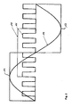
- a period 10 of the voltage of the secondary coil of a probe and the time course 11 of the clock is also referred to as clock in practice.
- the graph shows that the period of the voltage is an integer multiple of the period of the clock.
- the clock ensures that the voltage of the secondary coil is measured at maximum 12 and minimum 13.
- the mean determined from the amounts of the voltage at the maximum 12 and minimum 13 is indicated in the drawing by the reference numeral 14.
Landscapes
- Physics & Mathematics (AREA)
- General Physics & Mathematics (AREA)
- Engineering & Computer Science (AREA)
- Power Engineering (AREA)
- Measurement Of Length, Angles, Or The Like Using Electric Or Magnetic Means (AREA)
- Transmission And Conversion Of Sensor Element Output (AREA)
- Measurement Of Resistance Or Impedance (AREA)
Description
- Die Erfindung geht aus von einem Verfahren zum Auswerten von Längenmessungen, welche mit einem Differentialtransformator oder einer induktiven Halbbrücke durchgeführt werden, nach dem Oberbegriff des Anspruchs 1.
- Differentialtransformatoren und induktive Halbbrücken werden beispielsweise zur Längenmessung in der industriellen Fertigung, der Qualitätssicherung, der Prozesskontrolle, der Robotertechnik, der Luft- und Raumfahrt, der Automobilindustrie und bei hydraulischen und pneumatischen Anwendungen eingesetzt. Neben Längen oder Strecken können mit diesen Vorrichtungen auch die von Strecken ableitbaren Größen wie beispielsweise die Form eines Gegenstands bestimmt werden. Der Messbereich reicht vom Nanometerbereich bis in den Meterbereich. Das Prinzip der Längenmessung beruht darauf, dass eine mit einer sinusförmigen Erregerspannung gespeiste Primärspule über einen magnetisch wirksamen Kern mit einer oder zwei Sekundärspulen gekoppelt wird. Die Primärspule, die Sekundärspulen und der magnetisch wirksame Kern sind dabei in einen Messtaster integriert. Verändert der Kern bei der Längenmessung seine Position, so wirkt sich dies auf die magnetische Kopplung zwischen der Primärspule und die Sekundärspulen aus. Dabei ist die in der Sekundärspule induzierte Spannung linear von der Position des beweglichen Kerns abhängig. Die Spannung der Sekundärspule ist daher ein Maß für die Länge.
- Da die Erregerspannung sinusförmig ist, ist die an der Sekundärspule induzierte Spannung ebenfalls sinusförmig. Da als Ausgangssignal ein Gleichspannungssignal gewünscht ist, wird die an der Sekundärspule induzierte Spannung bei den aus dem Stand der Technik bekannten Verfahren demoduliert. Hierzu wird ein Demodulator verwendet, der die Wechselspannung gleichrichtet und durch Integration einen Effektivwert oder Mittelwert bildet. Die Gleichrichtung und die Integration erfolgt dabei durch geeignete elektrische Bauteile. Anschließend wird das Ausgangssignal durch einen Analog-Digital-Wandler digitalisiert und zur weiteren Auswertung an einen Rechner weitergeleitet.
- Solche Vorrichtungen sind aus der
Patentschriften US-A-4 857 919 undUS-A-4 450 443 bekannt. - Als nachteilig erweist sich bei derartigen Verfahren, dass zur Bestimmung eines Ausgangssignals über mehrere Perioden der Spannung der Sekundärspule gemittelt beziehungsweise integriert werden muss. Das Verfahren ist daher relativ langsam. Darüber hinaus wird das Ausgangssignal von der Güte der Erregerspannung beeinflusst. Oberwellen oder ein Offset reduzieren die Messgenauigkeit und führen zu einer Verfälschung des Ausgangssignals. Darüber hinaus wird das Ausgangssignal durch Effekte verfälscht, die beim Demodulieren auftreten.
- Die Erfindung und ihre Vorteile
- Demgegenüber hat das erfindungsgemäße Verfahren mit den Merkmalen des Anspruchs 1 den Vorteil, dass das Ausgangssignal ohne Demodulierung der sinusförmigen Spannung der Sekundärspule ermittelt wird. Verfälschungen oder Fehler, die beim Demodulieren auftreten, werden dadurch eliminiert. Das Ausgangssignal wird aus dem Mittelwert mindestens zweier Spannungswerte einer Periode der sinusförmigen Spannung der Sekundärspule abgeleitet. Hierzu wird beispielsweise der arithmetische, geometrische oder harmonische Mittelwert aus den Beträgen der Spannung zu mindestens zwei Zeitpunkten einer Periode bestimmt. Ein Offset oder Oberwellen verfälschen das Ausgangssignal daher nicht oder allenfalls in sehr geringem Maße.
- Zu jeder Periode der sinusförmigen Spannung der Sekundärspule wird der Mittelwert bestimmt um ein Ausgangssignal zu erhalten. Das Verfahren ist damit wesentlich schneller und präziser als die aus dem Stand der Technik bekannten Verfahren, bei denen über mehrere Periode gemittelt wird.
- Das Ausgangssignal wird mit einem Rechner weiterverarbeitet und häufig visualisiert. Das erfindungsgemäße Verfahren ermöglicht es, den induktiven Messtaster ohne den Umweg über zusätzliche elektrische Bauteile direkt an einen Rechner anzuschließen. Dieses Vorgehen ist kostengünstiger, weniger stark mit Messfehlern behaftet und bietet außerdem die Möglichkeit, eine Vielzahl unterschiedlicher Messtaster mit derselben Auswertehardware zu betreiben. Bei der Auswertehardware kann es sich beispielsweise um eine PC- oder PCI-Karte für einen Rechner oder um ein von einem Rechner unabhängiges Gerät handeln.
- Nach einer vorteilhaften Ausgestaltung der Erfindung werden als Spannungswerte einer Periode der in der Sekundärspule induzierten Spannung das Maximum und Minimum bestimmt. Darüber hinaus besteht eine weitere vorteilhafte Vorgehensweise darin, zwei Spannungswerte nahe dem Maximum und zwei Spannungswerte nahe dem Minimum einer Periode der in der Sekundärspule induzierten Spannung mit sinusförmigem Verlauf zu bestimmten und aus diesen vier Werten einen Mittelwert zu bestimmen.
- Nach einer weiteren vorteilhaften Ausgestaltung der Erfindung werden die Spannungswerte einer Periode, beispielsweise das Minimum und das Maximum, der Spannung der Sekundärspule digitalisiert, bevor der Mittelwert bestimmt wird. Aus den digitalisierten Werten kann anschließend in einem Logikbaustein der Mittelwert bestimmt werden. Bei einem derartigen Logikbaustein kann es sich beispielsweise um eine Programable Logic Device, kurz PLD, handeln.
- Nach einer weiteren vorteilhaften Ausgestaltung der Erfindung wird zu der sinusförmigen Erregerspannung der Primärspule ebenfalls das Maximum und Minimum einer Periode bestimmt. Anschließend wird zunächst der Mittelwert aus dem Maximum und Minimum und schließlich der Quotient aus dem Mittelwert der Sekundärspule und dem Mittelwert der Primärspule gebildet. Der Quotient oder ein aus dem Quotienten abgeleiteter Wert wird als Ausgangssignal ausgegeben. Durch die Bildung des Quotienten wird der Spannungsabfall am relativ langen Kabel des Messtasters eliminiert. Außerdem werden Störungen, die die Erregerspannung und damit auch die Spannung der Sekundärspule beeinflussen, im Ausgangssignal eliminiert. Bei derartigen Störungen kann es sich beispielsweise um eine Drift oder um temperaturbedingte Schwankungen handeln.
- Wie bei der Spannung der Sekundärspule können das Minimum und das Maximum einer Periode der Spannung der Primärspule digitalisiert werden, bevor der Mittelwert bestimmt wird. Aus den digitalisierten Werten kann anschließend in einem Logikbaustein der Mittelwert bestimmt und der Quotient aus den Mittelwerten der Sekundärspule und der Primärspule berechnet werden.
- Nach einer weiteren vorteilhaften Ausgestaltung der Erfindung wird die sinusförmige Erregerspannung unter Verwendung eines Taktgebers erzeugt. Derselbe Taktgeber dient dazu, die Zeitpunkte vorzugeben, zu denen die Spannungswerte einer Periode der sinusförmigen Spannung der Sekundärspule und eventuell der Primärspule gemessen werden. Anhand dieses Taktgebers werden die Erregerspannung einerseits und die Zeitpunkte der Messung der Minima und Maxima der Spannung der Sekundärspule andererseits synchronisiert. Damit wird gewährleistet, dass die Spannung der Sekundärspule exakt im Minimum und Maximum oder nahe dem Maximum und Minimum bestimmt wird. Verfälschungen des Ausgangssignals, die auf einer Spannungsmessung zu einem anderen Zeitpunkt beruhen, können ausgeschlossen werden. Zur Synchronisation trägt außerdem bei, dass die Phasendifferenz zwischen der Erregerspannung und der Spannung der Sekundärspule unterdrückt wird. Hierzu ist beispielsweise eine Phase-Frequenz-Detektion-Schaltung eines Phase-Locked Loop vorgesehen.
- Nach einer weiteren vorteilhaften Ausgestaltung der Erfindung ist die Frequenz des Taktgebers zur Bestimmung des Maximums und Minimums einer Periode der sinusförmigen Spannung der Sekundärspule ein ganzzahliges Vielfaches der Frequenz der Erregerspannung. Frequenzen mit derartigen Beziehungen zueinander erhält man beispielsweise durch Teilen einer vorgegebenen Frequenz. Diese wird beispielsweise durch einen Quarz vorgegebenen. Hierzu kann eine programmierbare Teilungseinrichtung, welche Teil der Auswertehardware ist, eingesetzt werden.
- Die komplette Elektronik für einen induktiven Messtaster mit einem Oszillator, Verstärkern, einem Analog-Digital-Wandler und einem Logikbaustein ist in einer Auswertehardware, beispielsweise auf einer industrietauglichen PCI-Karte untergebracht. Sie verfügt je nach Ausführung über 8 oder 16 Kanäle zum Anschluss von Messtastern. Je nach Bedarf können auch mehr oder weniger Kanäle vorgesehen sein. Der Rechner, in den die Karte eingesetzt ist, speist alle Primärspulen der Messtaster mit den notwendigen Wechselspannungen.
- Das Ausgangssignal, welches die Information über die gemessene Länge enthält, hat eine Auflösung von beispielsweise 16 Bit. Höhere Auflösungen sind möglich. Die Abtastfrequenzen liegen zwischen 2 und 50 Kilohertz. Auf der Auswertehardware sind die spezifischen Parameter verschiedener Modelle von induktiven Messtastern hinterlegt. Bei der Einrichtung muss lediglich aus einer Tabelle das jeweilige Modell ausgewählt werden. Die Einrichtung und Inbetriebnahme des Messtasters geschieht dann per Software. Zusätzlicher Aufwand bei der Installation, der Inbetriebnahme, der Handhabung und der Datenübertragung entfällt.
- Weitere Vorteile und vorteilhafte Ausgestaltungen der Erfindung sind der nachfolgenden Beschreibung, der Zeichnung und den Ansprüchen zu entnehmen.
- In der Zeichnung ist ein Ausführungsbeispiel einer Schaltung dargestellt, die nach dem erfindungsgemäße Verfahren arbeitet. Es zeigen:
- Figur 1
- vereinfachtes Blockschaltbild einer PCI-Karte,
- Figur 2
- Schaubild mit einer Periode der Spannung an der Sekundärspule und dem zeitlichen Verlauf des Taktgebers zur Messung des Maximums und Minimums der Spannung.
-
Figur 1 zeigt ein vereinfachtes Blockschaltbild einer PCI-Karte, welche mit den Elementen zur Durchführung des Verfahrens ausgestattet ist. Über den Messtaster-Stecker 1 werden die in der Zeichnung nicht dargestellten Messtaster mit der PCI-Karte verbunden. Auf der PCI-Karte befindet sich der Generator 2 zur Erzeugung der sinusförmigen Erregerspannung für die Primärspulen der Messtaster. Die Karte weist insgesamt 16 Eingänge für die Spannung der Sekundärspulen der Messtaster auf. Diese sind aufgeteilt in eine erste Gruppe von Eingängen 1 bis 8 mit der Bezugsziffer 3 und eine zweite Gruppe von Eingängen 9 bis 16 mit der Bezugsziffer 4. Außerdem ist ein Eingang 5 zur Messung der Erregerspannung vorgesehen. Diese dient dem Phasenabgleich zwischen der Spannung der Sekundärspulen und der Erregerspannung der Primärspulen. Eingänge 3, 4 und 5 sind mit zwei Analog-Digital-Wandlern 6 verbunden. Diese sind mit einem in der Zeichnung nicht dargestellten Taktgeber ausgestattet, der sowohl zur Erzeugung der Erregerspannung als auch zur Vorgabe der Zeitpunkte der Messung der Minima und Maxima der Spannung der Sekundärspule und der Erregerspannung dient. Diese Synchronisation zwischen den Analog-Digital-Wandlern 6 und dem Generator 2 ist inFigur 1 durch einen Pfeil mit der Beschriftung Synchro angedeutet. Die Analog-Digital-Wandler 6 digitalisieren die Spannungswerte der Sekundärspulen und der Primärspulen. Als Analog-Digital-Wandler können beispielsweise Sigma-Delta-Wandler verwendet werden. In der Programable Logic Device 7 werden die Mittelwerte aus dem Maximum und Minimum einer Periode der Spannung der Sekundärspule und der Primärspule bestimmt und der Quotient aus den beiden Mittelwerten gebildet. Zu jeder Periode der Spannung der Primärspule und der Sekundärspule wird der Quotient als Ausgangssignal über den PCI-Controller 8 und den PCI-Stecker 9 an den in der Zeichnung nicht dargestellten Rechner ausgegeben, in den die PCI-Karte eingesteckt ist. Das Ausgangssignal gibt Aufschluss über die gemessene Länge und kann im Rechner weiter aufbereitet, ausgewertet und auf dem Bildschirm des Rechners dargestellt werden. - In dem Schaubild in
Figur 2 sind eine Periode 10 der Spannung der Sekundärspule eines Messtasters und der zeitliche Verlauf 11 des Taktgebers dargestellt. Der Taktgeber wird in der Praxis auch als Clock bezeichnet. Aus dem Schaubild ergibt sich, dass die Periode der Spannung ein ganzzahliges Vielfaches der Periode des Taktgebers ist. Der Taktgeber sorgt dafür, dass die Spannung der Sekundärspule am Maximum 12 und Minimum 13 gemessen wird. Der aus den Beträgen der Spannung am Maximum 12 und Minimum 13 ermittelte Mittelwert ist in der Zeichnung mit der Bezugsziffer 14 gekennzeichnet. - Sämtliche Merkmale der Erfindung können sowohl einzeln als auch in beliebiger Kombination miteinander erfindungswesentlich sein.
-
- 1
- Messtaster-Stecker
- 2
- Generator
- 3
- Eingänge 1 bis 8
- 4
- Eingänge 9 bis 16
- 5
- Eingang für die Erregerspannung
- 6
- Analog-Digital-Wandler
- 7
- Programable Logic Device
- 8
- PCI-Controller
- 9
- PCI-Stecker
- 10
- Periode der Spannung der Sekundärspule
- 11
- zeitlicher Verlauf des Taktgebers
- 12
- Maximum
- 13
- Minimum
- 14
- Mittelwert
Claims (9)
- Verfahren zum Auswerten von mittels eines Differentialtransformators oder einer induktiven Halbbrücke mit einer Primärspule, einer Sekundärspule, einem magnetischen Kern und einem Generator zur Erzeugung einer sinusförmigen Erregerspannung durchgeführten Längenmessungen,
dadurch gekennzeichnet,
dass von der in der Sekundärspule durch die Verschiebung des Kerns induzierten Spannung mit sinusförmigem Verlauf mindestens zwei Spannungswerte einer Periode bestimmt werden,
dass als Spannungswerte der in der Sekundärspule durch die Verschiebung des Kerns induzierten Spannung mit sinusförmigem Verlauf das Minimum und das Maximum einer Periode bestimmt werden, oder
dass als Spannungswerte der in der Sekundärspule durch die Verschiebung des Kerns induzierten Spannung mit sinusförmigem Verlauf zwei Spannungswerte nahe dem Maximum und zwei Spannungswerte nahe dem Minimum einer Periode bestimmt werden,
dass aus den Beträgen der mindestens zwei Spannungswerte ein Mittelwert gebildet wird,
und dass der Mittelwert oder ein aus dem Mittelwert abgeleiteter Wert als Ausgangssignal für die gemessene Länge ausgegeben wird. - Verfahren nach einem der vorhergehenden Ansprüche, dadurch gekennzeichnet, dass die Spannungswerte einer Periode der Spannung der Sekundärspule digitalisiert werden.
- Verfahren nach einem der vorhergehenden Ansprüche, dadurch gekennzeichnet, dass von der sinusförmigen Erregerspannung der Primärspule das Maximum und Minimum jeweils einer Periode bestimmt werden,
dass aus dem Maximum und Minimum ein Mittelwert gebildet wird,
dass der Quotient aus dem Mittelwert der Sekundärspule und dem Mittelwert der Primärspule gebildet wird,
und dass der Quotient oder ein aus dem Quotienten abgeleiteter Wert als Ausgangssignal für die gemessene Länge ausgegeben wird. - Verfahren nach Anspruch 3, dadurch gekennzeichnet, dass das Minimum und das Maximum einer Periode der Erregerspannung der Primärspule digitalisiert werden.
- Verfahren nach einem der vorhergehenden Ansprüche, dadurch gekennzeichnet, dass die Erregerspannung unter Verwendung eines Taktgebers erzeugt wird, und dass die Zeitpunkte, zu denen das Spannungswerte einer Periode der sinusförmigen Spannung der Sekundärspule bestimmt werden, durch denselben Taktgeber vorgegeben werden.
- Verfahren nach Anspruch 5, dadurch gekennzeichnet, dass die Frequenz des Taktgebers zur Bestimmung der Spannungswerte einer Periode der sinusförmigen Spannung der Sekundärspule ein ganzzahliges Vielfaches der Frequenz der Erregerspannung ist.
- Verfahren nach Anspruch 5 oder 6, dadurch gekennzeichnet, dass als Taktgeber ein Quarz verwendet wird, dessen Frequenz mittels einer Teilungseinrichtung heruntergeteilt und dadurch reduziert wird.
- Verfahren nach einem der vorhergehenden Ansprüche, dadurch gekennzeichnet, dass die Phasendifferenz zwischen der Erregerspannung und der Spannung an der Sekundärspule eliminiert wird.
- Verfahren nach Anspruch 8, dadurch gekennzeichnet, dass zur Eliminierung der Phasendifferenz eine Phase-Frequenz-Detektion-Schaltung verwendet.
Applications Claiming Priority (1)
| Application Number | Priority Date | Filing Date | Title |
|---|---|---|---|
| DE102004055802A DE102004055802A1 (de) | 2004-11-18 | 2004-11-18 | Verfahren zum Auswerten von mittels eines Differentialtransformators oder einer induktiven Halbbrücke durchgeführten Längenmessungen |
Publications (3)
| Publication Number | Publication Date |
|---|---|
| EP1659372A2 EP1659372A2 (de) | 2006-05-24 |
| EP1659372A3 EP1659372A3 (de) | 2007-01-17 |
| EP1659372B1 true EP1659372B1 (de) | 2008-02-27 |
Family
ID=35967005
Family Applications (1)
| Application Number | Title | Priority Date | Filing Date |
|---|---|---|---|
| EP05025118A Expired - Lifetime EP1659372B1 (de) | 2004-11-18 | 2005-11-17 | Verfahren zum Auswerten von mittels eines Differenzialtransformators oder einer induktiven Halbbrücke durchgeführten Längenmessungen |
Country Status (3)
| Country | Link |
|---|---|
| EP (1) | EP1659372B1 (de) |
| AT (1) | ATE387621T1 (de) |
| DE (2) | DE102004055802A1 (de) |
Families Citing this family (1)
| Publication number | Priority date | Publication date | Assignee | Title |
|---|---|---|---|---|
| DE102017108912B3 (de) | 2017-04-26 | 2018-06-14 | Messtechnik Sachs Gmbh | Verfahren zur Auswertung eines Messsignals eines induktiven Messsensors sowie ein Längenmesssystem |
Family Cites Families (3)
| Publication number | Priority date | Publication date | Assignee | Title |
|---|---|---|---|---|
| US4450443A (en) * | 1982-03-18 | 1984-05-22 | The Garrett Corporation | Position transducer for digital systems |
| US4857919A (en) * | 1987-09-14 | 1989-08-15 | Conoco Inc. | Method and apparatus for indicating the position of a core member of a variable differential transformer |
| US5717331A (en) * | 1995-09-22 | 1998-02-10 | H.R. Textron, Inc. | Demodulator circuit for use with a displacement sensor to provide position information |
-
2004
- 2004-11-18 DE DE102004055802A patent/DE102004055802A1/de not_active Withdrawn
-
2005
- 2005-11-17 AT AT05025118T patent/ATE387621T1/de active
- 2005-11-17 DE DE502005002970T patent/DE502005002970D1/de not_active Expired - Lifetime
- 2005-11-17 EP EP05025118A patent/EP1659372B1/de not_active Expired - Lifetime
Also Published As
| Publication number | Publication date |
|---|---|
| DE502005002970D1 (de) | 2008-04-10 |
| EP1659372A2 (de) | 2006-05-24 |
| EP1659372A3 (de) | 2007-01-17 |
| DE102004055802A1 (de) | 2006-05-24 |
| ATE387621T1 (de) | 2008-03-15 |
Similar Documents
| Publication | Publication Date | Title |
|---|---|---|
| EP2715384B1 (de) | Verfahren zum betreiben einer hallsensoranordnung und hallsensoranordnung | |
| DE10111975B9 (de) | Verfahren zur Fehlererfassung für eine Vorrichtung zur Positionserfassung mit elektromagnetischer Induktion | |
| EP3589961B1 (de) | Verfahren zur strommessung und strommessvorrichtung | |
| DE112016006971T5 (de) | Verfahren und Vorrichtung zum Herausfinden des Phasenfehlers oder von Timing-Verzögerungen in einem Stromwandler und Leistungsmessvorrichtung einschließlich Stromwandlerfehlerkorrektur | |
| EP2555019B1 (de) | Induktiver Näherungssensor | |
| EP3391063B1 (de) | Mobile transformatorprüfvorrichtung und verfahren zum prüfen eines leistungstransformators | |
| EP2215490B1 (de) | Verfahren zur detektion von interlaminaren blechschlüssen im stator-blechpaket von elektromaschinen | |
| DE19744651A1 (de) | Halbleitertestvorrichtung zum Messen des Versorgungsstromes einer Halbleitereinrichtung | |
| AT516556B1 (de) | Messsystem mit resonanten Sensoren und Verfahren zum Betrieb eines Resonators | |
| EP1203961A1 (de) | Verfahren zum Messen des Widerstands und der Induktivität einer Leitung | |
| EP2905627B1 (de) | Vorrichtung und Verfahren zur kontaktlosen, präzisen Messung des Gleichstromanteils in einem Mischstrom | |
| EP2567263B1 (de) | Erfassung eines metallischen oder magnetischen objekts | |
| DE3689956T2 (de) | Bestimmung des Effektivwertes des Stromes durch Abtastung des differentiellen Stromes. | |
| EP3074726B1 (de) | Induktiver messtaster und verfahren zum betreiben eines induktiven messtasters | |
| DE102014216404B4 (de) | Strommessvorrichtung und Verfahren zum Erfassen eines Stroms | |
| EP1659372B1 (de) | Verfahren zum Auswerten von mittels eines Differenzialtransformators oder einer induktiven Halbbrücke durchgeführten Längenmessungen | |
| DE10225191A1 (de) | Analog-Digital-Signal-Umwandlungsverfahren- und Vorrichtung | |
| EP0881476A2 (de) | Trägerfrequenzmessverfahren | |
| EP3598180A1 (de) | Detektor zum detektieren von elektrisch leitfähigem material | |
| DE4013916C2 (de) | Vorrichtung zum Erkennen der Form und Beschaffenheit der Mantelflächen von zylindrischen metallischen Werkstücken | |
| EP0066681A1 (de) | Verfahren zur Ermittlung einer dem Tastverhältnis entsprechenden Grösse eines periodischen elektrischen Rechtecksignals und Verfahren zur Ermittlung des Phasenwinkels zwischen zwei zueinander phasenverschobenen, periodischen elektrischen Rechtsignalen und Anordnung zur Durchführung dieser Verfahren | |
| DE102016121334A1 (de) | Messwandler | |
| LU101628B1 (de) | Strommessumformer zum Messen des durch einen elektrischen Leiter fließenden Stroms und Verfahren zur Ausgabe der Stromstärke bei einem Strommessumformer mit Ausgabe der Energieflussrichtung bei Wechselströmen | |
| DE102018124090A1 (de) | Elektronische Schaltung für einen elektrochemischen Sensor und Verfahren zur Messung einer Impedanz von mindestens einem Messkanal des elektrochemischen Sensors | |
| DE102011014317B4 (de) | Sensorüberwachung einer Positionsmessvorrichtung mittels Wärmerauschen |
Legal Events
| Date | Code | Title | Description |
|---|---|---|---|
| PUAI | Public reference made under article 153(3) epc to a published international application that has entered the european phase |
Free format text: ORIGINAL CODE: 0009012 |
|
| AK | Designated contracting states |
Kind code of ref document: A2 Designated state(s): AT BE BG CH CY CZ DE DK EE ES FI FR GB GR HU IE IS IT LI LT LU LV MC NL PL PT RO SE SI SK TR |
|
| AX | Request for extension of the european patent |
Extension state: AL BA HR MK YU |
|
| PUAL | Search report despatched |
Free format text: ORIGINAL CODE: 0009013 |
|
| AK | Designated contracting states |
Kind code of ref document: A3 Designated state(s): AT BE BG CH CY CZ DE DK EE ES FI FR GB GR HU IE IS IT LI LT LU LV MC NL PL PT RO SE SI SK TR |
|
| AX | Request for extension of the european patent |
Extension state: AL BA HR MK YU |
|
| RIC1 | Information provided on ipc code assigned before grant |
Ipc: G01D 5/20 20060101AFI20060316BHEP Ipc: G01D 5/22 20060101ALI20061211BHEP |
|
| 17P | Request for examination filed |
Effective date: 20070227 |
|
| 17Q | First examination report despatched |
Effective date: 20070405 |
|
| AKX | Designation fees paid |
Designated state(s): AT BE BG CH CY CZ DE DK EE ES FI FR GB GR HU IE IS IT LI LT LU LV MC NL PL PT RO SE SI SK TR |
|
| GRAP | Despatch of communication of intention to grant a patent |
Free format text: ORIGINAL CODE: EPIDOSNIGR1 |
|
| GRAS | Grant fee paid |
Free format text: ORIGINAL CODE: EPIDOSNIGR3 |
|
| GRAA | (expected) grant |
Free format text: ORIGINAL CODE: 0009210 |
|
| AK | Designated contracting states |
Kind code of ref document: B1 Designated state(s): AT BE BG CH CY CZ DE DK EE ES FI FR GB GR HU IE IS IT LI LT LU LV MC NL PL PT RO SE SI SK TR |
|
| REG | Reference to a national code |
Ref country code: GB Ref legal event code: FG4D Free format text: NOT ENGLISH |
|
| REG | Reference to a national code |
Ref country code: CH Ref legal event code: EP |
|
| REG | Reference to a national code |
Ref country code: IE Ref legal event code: FG4D Free format text: LANGUAGE OF EP DOCUMENT: GERMAN |
|
| REF | Corresponds to: |
Ref document number: 502005002970 Country of ref document: DE Date of ref document: 20080410 Kind code of ref document: P |
|
| REG | Reference to a national code |
Ref country code: DE Ref legal event code: R096 Ref document number: 502005002970 Country of ref document: DE Effective date: 20080410 |
|
| PG25 | Lapsed in a contracting state [announced via postgrant information from national office to epo] |
Ref country code: FI Free format text: LAPSE BECAUSE OF FAILURE TO SUBMIT A TRANSLATION OF THE DESCRIPTION OR TO PAY THE FEE WITHIN THE PRESCRIBED TIME-LIMIT Effective date: 20080227 Ref country code: IS Free format text: LAPSE BECAUSE OF FAILURE TO SUBMIT A TRANSLATION OF THE DESCRIPTION OR TO PAY THE FEE WITHIN THE PRESCRIBED TIME-LIMIT Effective date: 20080627 Ref country code: ES Free format text: LAPSE BECAUSE OF FAILURE TO SUBMIT A TRANSLATION OF THE DESCRIPTION OR TO PAY THE FEE WITHIN THE PRESCRIBED TIME-LIMIT Effective date: 20080607 |
|
| NLV1 | Nl: lapsed or annulled due to failure to fulfill the requirements of art. 29p and 29m of the patents act | ||
| PG25 | Lapsed in a contracting state [announced via postgrant information from national office to epo] |
Ref country code: PL Free format text: LAPSE BECAUSE OF FAILURE TO SUBMIT A TRANSLATION OF THE DESCRIPTION OR TO PAY THE FEE WITHIN THE PRESCRIBED TIME-LIMIT Effective date: 20080227 Ref country code: LV Free format text: LAPSE BECAUSE OF FAILURE TO SUBMIT A TRANSLATION OF THE DESCRIPTION OR TO PAY THE FEE WITHIN THE PRESCRIBED TIME-LIMIT Effective date: 20080227 Ref country code: SI Free format text: LAPSE BECAUSE OF FAILURE TO SUBMIT A TRANSLATION OF THE DESCRIPTION OR TO PAY THE FEE WITHIN THE PRESCRIBED TIME-LIMIT Effective date: 20080227 |
|
| REG | Reference to a national code |
Ref country code: IE Ref legal event code: FD4D |
|
| PG25 | Lapsed in a contracting state [announced via postgrant information from national office to epo] |
Ref country code: SK Free format text: LAPSE BECAUSE OF FAILURE TO SUBMIT A TRANSLATION OF THE DESCRIPTION OR TO PAY THE FEE WITHIN THE PRESCRIBED TIME-LIMIT Effective date: 20080227 Ref country code: DK Free format text: LAPSE BECAUSE OF FAILURE TO SUBMIT A TRANSLATION OF THE DESCRIPTION OR TO PAY THE FEE WITHIN THE PRESCRIBED TIME-LIMIT Effective date: 20080227 Ref country code: IE Free format text: LAPSE BECAUSE OF FAILURE TO SUBMIT A TRANSLATION OF THE DESCRIPTION OR TO PAY THE FEE WITHIN THE PRESCRIBED TIME-LIMIT Effective date: 20080227 Ref country code: SE Free format text: LAPSE BECAUSE OF FAILURE TO SUBMIT A TRANSLATION OF THE DESCRIPTION OR TO PAY THE FEE WITHIN THE PRESCRIBED TIME-LIMIT Effective date: 20080527 Ref country code: PT Free format text: LAPSE BECAUSE OF FAILURE TO SUBMIT A TRANSLATION OF THE DESCRIPTION OR TO PAY THE FEE WITHIN THE PRESCRIBED TIME-LIMIT Effective date: 20080721 Ref country code: NL Free format text: LAPSE BECAUSE OF FAILURE TO SUBMIT A TRANSLATION OF THE DESCRIPTION OR TO PAY THE FEE WITHIN THE PRESCRIBED TIME-LIMIT Effective date: 20080227 |
|
| PG25 | Lapsed in a contracting state [announced via postgrant information from national office to epo] |
Ref country code: RO Free format text: LAPSE BECAUSE OF FAILURE TO SUBMIT A TRANSLATION OF THE DESCRIPTION OR TO PAY THE FEE WITHIN THE PRESCRIBED TIME-LIMIT Effective date: 20080227 |
|
| EN | Fr: translation not filed | ||
| PLBE | No opposition filed within time limit |
Free format text: ORIGINAL CODE: 0009261 |
|
| STAA | Information on the status of an ep patent application or granted ep patent |
Free format text: STATUS: NO OPPOSITION FILED WITHIN TIME LIMIT |
|
| PG25 | Lapsed in a contracting state [announced via postgrant information from national office to epo] |
Ref country code: LT Free format text: LAPSE BECAUSE OF FAILURE TO SUBMIT A TRANSLATION OF THE DESCRIPTION OR TO PAY THE FEE WITHIN THE PRESCRIBED TIME-LIMIT Effective date: 20080227 Ref country code: CZ Free format text: LAPSE BECAUSE OF FAILURE TO SUBMIT A TRANSLATION OF THE DESCRIPTION OR TO PAY THE FEE WITHIN THE PRESCRIBED TIME-LIMIT Effective date: 20080227 |
|
| 26N | No opposition filed |
Effective date: 20081128 |
|
| REG | Reference to a national code |
Ref country code: DE Ref legal event code: R097 Ref document number: 502005002970 Country of ref document: DE Effective date: 20081128 |
|
| PG25 | Lapsed in a contracting state [announced via postgrant information from national office to epo] |
Ref country code: FR Free format text: LAPSE BECAUSE OF FAILURE TO SUBMIT A TRANSLATION OF THE DESCRIPTION OR TO PAY THE FEE WITHIN THE PRESCRIBED TIME-LIMIT Effective date: 20081219 Ref country code: BG Free format text: LAPSE BECAUSE OF FAILURE TO SUBMIT A TRANSLATION OF THE DESCRIPTION OR TO PAY THE FEE WITHIN THE PRESCRIBED TIME-LIMIT Effective date: 20080527 Ref country code: EE Free format text: LAPSE BECAUSE OF FAILURE TO SUBMIT A TRANSLATION OF THE DESCRIPTION OR TO PAY THE FEE WITHIN THE PRESCRIBED TIME-LIMIT Effective date: 20080227 |
|
| BERE | Be: lapsed |
Owner name: ADDI-DATA G.M.B.H. Effective date: 20081130 |
|
| PG25 | Lapsed in a contracting state [announced via postgrant information from national office to epo] |
Ref country code: MC Free format text: LAPSE BECAUSE OF NON-PAYMENT OF DUE FEES Effective date: 20081130 |
|
| PG25 | Lapsed in a contracting state [announced via postgrant information from national office to epo] |
Ref country code: CY Free format text: LAPSE BECAUSE OF FAILURE TO SUBMIT A TRANSLATION OF THE DESCRIPTION OR TO PAY THE FEE WITHIN THE PRESCRIBED TIME-LIMIT Effective date: 20080227 |
|
| PG25 | Lapsed in a contracting state [announced via postgrant information from national office to epo] |
Ref country code: IT Free format text: LAPSE BECAUSE OF FAILURE TO SUBMIT A TRANSLATION OF THE DESCRIPTION OR TO PAY THE FEE WITHIN THE PRESCRIBED TIME-LIMIT Effective date: 20080227 |
|
| PG25 | Lapsed in a contracting state [announced via postgrant information from national office to epo] |
Ref country code: BE Free format text: LAPSE BECAUSE OF NON-PAYMENT OF DUE FEES Effective date: 20081130 |
|
| GBPC | Gb: european patent ceased through non-payment of renewal fee |
Effective date: 20091117 |
|
| PG25 | Lapsed in a contracting state [announced via postgrant information from national office to epo] |
Ref country code: LU Free format text: LAPSE BECAUSE OF NON-PAYMENT OF DUE FEES Effective date: 20081117 Ref country code: HU Free format text: LAPSE BECAUSE OF FAILURE TO SUBMIT A TRANSLATION OF THE DESCRIPTION OR TO PAY THE FEE WITHIN THE PRESCRIBED TIME-LIMIT Effective date: 20080828 |
|
| PG25 | Lapsed in a contracting state [announced via postgrant information from national office to epo] |
Ref country code: TR Free format text: LAPSE BECAUSE OF FAILURE TO SUBMIT A TRANSLATION OF THE DESCRIPTION OR TO PAY THE FEE WITHIN THE PRESCRIBED TIME-LIMIT Effective date: 20080227 |
|
| PG25 | Lapsed in a contracting state [announced via postgrant information from national office to epo] |
Ref country code: GR Free format text: LAPSE BECAUSE OF FAILURE TO SUBMIT A TRANSLATION OF THE DESCRIPTION OR TO PAY THE FEE WITHIN THE PRESCRIBED TIME-LIMIT Effective date: 20080528 |
|
| PG25 | Lapsed in a contracting state [announced via postgrant information from national office to epo] |
Ref country code: GB Free format text: LAPSE BECAUSE OF NON-PAYMENT OF DUE FEES Effective date: 20091117 |
|
| P01 | Opt-out of the competence of the unified patent court (upc) registered |
Effective date: 20230512 |
|
| PGFP | Annual fee paid to national office [announced via postgrant information from national office to epo] |
Ref country code: DE Payment date: 20231120 Year of fee payment: 19 Ref country code: CH Payment date: 20231201 Year of fee payment: 19 Ref country code: AT Payment date: 20231117 Year of fee payment: 19 |
|
| REG | Reference to a national code |
Ref country code: DE Ref legal event code: R119 Ref document number: 502005002970 Country of ref document: DE |
|
| REG | Reference to a national code |
Ref country code: CH Ref legal event code: PL |
|
| REG | Reference to a national code |
Ref country code: AT Ref legal event code: MM01 Ref document number: 387621 Country of ref document: AT Kind code of ref document: T Effective date: 20241117 Ref country code: CH Ref legal event code: PL |
|
| PG25 | Lapsed in a contracting state [announced via postgrant information from national office to epo] |
Ref country code: CH Free format text: LAPSE BECAUSE OF NON-PAYMENT OF DUE FEES Effective date: 20241130 |
|
| PG25 | Lapsed in a contracting state [announced via postgrant information from national office to epo] |
Ref country code: AT Free format text: LAPSE BECAUSE OF NON-PAYMENT OF DUE FEES Effective date: 20241117 |
|
| PG25 | Lapsed in a contracting state [announced via postgrant information from national office to epo] |
Ref country code: DE Free format text: LAPSE BECAUSE OF NON-PAYMENT OF DUE FEES Effective date: 20250603 |