EP1659413A1 - Trenntransformator - Google Patents
Trenntransformator Download PDFInfo
- Publication number
- EP1659413A1 EP1659413A1 EP04405726A EP04405726A EP1659413A1 EP 1659413 A1 EP1659413 A1 EP 1659413A1 EP 04405726 A EP04405726 A EP 04405726A EP 04405726 A EP04405726 A EP 04405726A EP 1659413 A1 EP1659413 A1 EP 1659413A1
- Authority
- EP
- European Patent Office
- Prior art keywords
- power supply
- voltage
- circuit
- high voltage
- sensor
- Prior art date
- Legal status (The legal status is an assumption and is not a legal conclusion. Google has not performed a legal analysis and makes no representation as to the accuracy of the status listed.)
- Granted
Links
- 238000002955 isolation Methods 0.000 title description 3
- 238000005259 measurement Methods 0.000 claims abstract description 13
- 239000004020 conductor Substances 0.000 claims abstract description 9
- 239000013307 optical fiber Substances 0.000 claims description 3
- 239000012212 insulator Substances 0.000 claims 1
- 239000003822 epoxy resin Substances 0.000 abstract description 2
- 239000000463 material Substances 0.000 abstract description 2
- 229920000647 polyepoxide Polymers 0.000 abstract description 2
- 230000008878 coupling Effects 0.000 description 10
- 238000010168 coupling process Methods 0.000 description 10
- 238000005859 coupling reaction Methods 0.000 description 10
- 238000010292 electrical insulation Methods 0.000 description 5
- 230000015556 catabolic process Effects 0.000 description 4
- 230000004048 modification Effects 0.000 description 2
- 238000012986 modification Methods 0.000 description 2
- 230000003071 parasitic effect Effects 0.000 description 2
- 230000009467 reduction Effects 0.000 description 2
- 229920005989 resin Polymers 0.000 description 2
- 239000011347 resin Substances 0.000 description 2
- 230000008901 benefit Effects 0.000 description 1
- 230000005540 biological transmission Effects 0.000 description 1
- 238000006243 chemical reaction Methods 0.000 description 1
- 238000010276 construction Methods 0.000 description 1
- 230000001419 dependent effect Effects 0.000 description 1
- 238000010586 diagram Methods 0.000 description 1
- 238000001914 filtration Methods 0.000 description 1
- 238000010438 heat treatment Methods 0.000 description 1
- 238000003780 insertion Methods 0.000 description 1
- 230000037431 insertion Effects 0.000 description 1
- 239000011810 insulating material Substances 0.000 description 1
- 238000009413 insulation Methods 0.000 description 1
- 239000002184 metal Substances 0.000 description 1
- 230000035699 permeability Effects 0.000 description 1
- 230000001131 transforming effect Effects 0.000 description 1
- 235000012431 wafers Nutrition 0.000 description 1
Images


Classifications
-
- G—PHYSICS
- G01—MEASURING; TESTING
- G01R—MEASURING ELECTRIC VARIABLES; MEASURING MAGNETIC VARIABLES
- G01R15/00—Details of measuring arrangements of the types provided for in groups G01R17/00 - G01R29/00, G01R33/00 - G01R33/26 or G01R35/00
- G01R15/14—Adaptations providing voltage or current isolation, e.g. for high-voltage or high-current networks
-
- H—ELECTRICITY
- H01—ELECTRIC ELEMENTS
- H01F—MAGNETS; INDUCTANCES; TRANSFORMERS; SELECTION OF MATERIALS FOR THEIR MAGNETIC PROPERTIES
- H01F30/00—Fixed transformers not covered by group H01F19/00
- H01F30/06—Fixed transformers not covered by group H01F19/00 characterised by the structure
- H01F30/16—Toroidal transformers
-
- H—ELECTRICITY
- H01—ELECTRIC ELEMENTS
- H01F—MAGNETS; INDUCTANCES; TRANSFORMERS; SELECTION OF MATERIALS FOR THEIR MAGNETIC PROPERTIES
- H01F19/00—Fixed transformers or mutual inductances of the signal type
- H01F19/04—Transformers or mutual inductances suitable for handling frequencies considerably beyond the audio range
- H01F19/08—Transformers having magnetic bias, e.g. for handling pulses
-
- H—ELECTRICITY
- H01—ELECTRIC ELEMENTS
- H01F—MAGNETS; INDUCTANCES; TRANSFORMERS; SELECTION OF MATERIALS FOR THEIR MAGNETIC PROPERTIES
- H01F27/00—Details of transformers or inductances, in general
- H01F27/34—Special means for preventing or reducing unwanted electric or magnetic effects, e.g. no-load losses, reactive currents, harmonics, oscillations, leakage fields
Definitions
- the present invention relates to a power supply for circuits or electronic devices arranged in a high voltage environment and requiring electrical insulation, among others for security reasons.
- the invention particularly relates to a power supply for a measuring device, in particular an electric sensor, arranged in a high voltage environment.
- Another solution would be to provide electrical energy for the operation of the electronic device by drawing this energy from the low voltage side.
- Such a power supply would eliminate or reduce the aforementioned drawbacks, but would then require solving the problem of electrical insulation.
- GB-A-2307795 describes an isolating transformer with two or three magnetic circuits, coupled together by intermediate coils, on the primary side to a primary coil, and on the secondary side to a secondary coil.
- US 4,172,244 it is also proposed to provide an intermediate magnetic circuit between the magnetic circuits of the primary and secondary sides, in order to achieve electrical isolation and reduce the leakage currents caused by the capacitive coupling.
- the proposed measures for the reduction of the capacitive coupling include the insertion of electrical shielding around the coils and the reduction of the number of turns of the intermediate coils coupling the magnetic circuits to each other.
- an object of the invention is to provide a power system for an electronic circuit arranged in a high voltage environment having a very good electrical insulation, a low level of partial discharges, a low emission of spurious electromagnetic waves and low capacitive coupling, even for high common mode dv / dt on the high voltage side.
- Another object of the invention is to provide a device for measuring electrical values of high voltage lines that is accurate, reliable and can experience large variations in dv / dt in common mode.
- a power supply for circuits in a high-voltage environment includes an isolator device interconnecting the low-voltage side (secondary side) with the high-voltage side (primary side), the isolator device comprising a primary-side magnetic circuit coupled by means of a primary coil to a power supply of the electronic circuit in the high voltage environment, a secondary side magnetic circuit coupled by means of a secondary coil to a current source, and at least one magnetic circuit intermediate between the primary and secondary magnetic circuits coupled to these by means of intermediate coils, the intermediate coils comprising parts of turns mounted on at least one circuit board.
- the turn portions are preferably in the form of "U" shaped conductors.
- the one or more circuit boards preferably comprise conductive tracks for interconnecting the "U" conductors in order to close the turns of the intermediate coils.
- circuit boards there are at least two circuit boards, one on the primary side and one on the secondary side, separated by an air gap or a space filled with an insulating material, such as an epoxy resin, to increase the resistance to breakdown and resistance to electrical surface leakage.
- an insulating material such as an epoxy resin
- the "U" conductors of the coil portions of the intermediate coils of the isolating device may be formed by stamping and arranged to be spaced apart from the magnetic circuit by a space corresponding to about one quarter of the diameter of the opening formed by the magnetic circuit. , or more. This greatly reduces the capacitive coupling between the coils and the magnetic circuits.
- the intermediate coils can advantageously form a substantially "8" shaped closed loop to cancel the magnetic fields of leakage generated in these coils.
- the low-voltage electrical power source is a stabilized sinusoidal voltage source, in order to avoid the generation of high harmonic frequencies which can disturb the measurement signals.
- the high voltage side supply may comprise a rectifier and filter circuit for generating a direct current without a frequency component.
- an apparatus for measuring electrical values of high-voltage lines comprising a supply device as described above, a sensor arranged on the high-voltage side and a treatment unit arranged on the low-voltage side.
- the sensor may comprise a differential voltage sensor for measuring differential voltages between two high voltage phases, and a digital analog converter for transmitting the measurement signals to the processing unit.
- the sensor may further comprise an oscillator connected to the digital analog converter and sending a synchronization signal to a digital to analog converter of the processing unit in parallel with the digital measurement signal.
- the processing unit and the sensor can communicate by means of optical fibers.
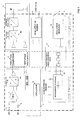
- an electrical value measuring device 1 comprises a power supply system 2, a signal processing unit 5, and a differential voltage sensor 3 arranged in a high-voltage environment. (primary side) and able to measure electrical values of high voltage lines.
- the voltage sensor measures the differential voltage between two phases of the railway high-voltage lines with potentials up to 6kV.
- the sensor transmits the measurement signals by a non-electrically conductive path, such as an optical fiber 4, alternatively by electromagnetic waves, to the signal processing unit 5 disposed on the low voltage side (secondary side).
- the measuring device may comprise a housing 23 in which the power supply and the signal processing circuits are mounted, the housing being able to be filled with a resin after the components (2, 3, 4, 5) have been assembled.
- the electronic circuit 3 of the sensor may comprise an analog-to-digital converter 6a in order to convert the analog measurement signals, coming out of a differential amplifier 7 connected through impedances 8 to the terminals of a sensor coupled to the two phases, into digital signals. for their transmission to the signal processing unit 5.
- an oscillator 9 of the sensor transmits a synchronization signal.
- the power supply system 2 comprises a voltage source 10 of the low voltage side, preferably a stabilized sinusoidal voltage source, coupled through an isolator device 11 to a power supply unit 12 disposed on the high voltage side.
- the power unit is connected to the electronic circuit of the sensor 3 for its power supply.
- the power supply unit 12 comprises a rectifying and filtering circuit for transforming the input sinusoidal current into a DC current without a frequency component.
- the sinusoidal current source 10 has the advantage, compared to switched current sources, of eliminating or reducing high harmonic frequencies induced by the switched sources, so as not to disturb the measurement signal produced by the sensor. 3 and processed by the treatment unit 5.
- the isolating device (see in particular FIGS. 1, 3a and 4) comprises at least three magnetic circuits 13a, 13b, 13c, a circuit on the primary side 13a, a circuit on the secondary side 13c and an intermediate circuit 13b, the circuits preferably being in the form of toric elements of a material having good magnetic permeability.
- the isolator device further comprises a primary coil 14 connected to the primary power supply unit 12, a secondary coil 15 connected to the voltage source 10 and intermediate coils 16, 17 mounted on circuit supports 18, 19 in the form of printed circuit boards.
- the intermediate coils comprise intermediate turns 16a, 16b, 17a, 17b formed in part by metal pieces preferably stamped, in U-shaped, mounted on the circuit boards 18, 19 and electrically interconnected by conductive tracks on the wafers, so as to form a closed loop substantially in the form of "8", as illustrated in FIG. 4.
- the tracks 21, 22 may be arranged in different layers of a multilayer printed circuit, to allow their crossing to form the loop "8".
- the arrangement of the intermediate "U” turns on a printed circuit makes it possible to space the turns of the magnetic circuit well in order to reduce the capacitive coupling, in particular between the conductors of the intermediate coils. , 17 and the magnetic circuits.
- the low number of turns of the intermediate coils also makes it possible to reduce the capacitive coupling and to achieve good galvanic isolation.
- intersection of the intermediate turns 16a and 16b, respectively 17a and 17b, makes it possible to cancel the magnetic leakage fields H 1, H 2 (see FIG 4) generated by the half-loops of the "8" -shaped coil, and consequently to reduce the parasitic magnetic fields that can be emitted by the isolator device.
- Fig. 3a Mounting the primary and secondary sides on separate circuit boards 18, 19 (Fig. 3a) advantageously increases the breakdown voltage of the device and eliminates surface leakage currents, due to the air space, or filled of an insulating resin, between the platelets.
Landscapes
- Engineering & Computer Science (AREA)
- Power Engineering (AREA)
- Physics & Mathematics (AREA)
- General Physics & Mathematics (AREA)
- Measuring Instrument Details And Bridges, And Automatic Balancing Devices (AREA)
- Power Conversion In General (AREA)
- Regulation Of General Use Transformers (AREA)
- Transformers For Measuring Instruments (AREA)
- Coils Or Transformers For Communication (AREA)
Priority Applications (7)
| Application Number | Priority Date | Filing Date | Title |
|---|---|---|---|
| EP04405726A EP1659413B1 (de) | 2004-11-23 | 2004-11-23 | Trenntransformator |
| DE602004032147T DE602004032147D1 (de) | 2004-11-23 | 2004-11-23 | Trenntransformator |
| AT04405726T ATE504842T1 (de) | 2004-11-23 | 2004-11-23 | Trenntransformator |
| US11/791,239 US20080303512A1 (en) | 2004-11-23 | 2005-10-21 | Isolating Transformer |
| PCT/IB2005/003199 WO2006056833A1 (fr) | 2004-11-23 | 2005-10-21 | Transformateur d’isolation |
| JP2007542139A JP2008521231A (ja) | 2004-11-23 | 2005-10-21 | 絶縁変圧器 |
| CN2005800400732A CN101065675B (zh) | 2004-11-23 | 2005-10-21 | 隔离变压器 |
Applications Claiming Priority (1)
| Application Number | Priority Date | Filing Date | Title |
|---|---|---|---|
| EP04405726A EP1659413B1 (de) | 2004-11-23 | 2004-11-23 | Trenntransformator |
Publications (2)
| Publication Number | Publication Date |
|---|---|
| EP1659413A1 true EP1659413A1 (de) | 2006-05-24 |
| EP1659413B1 EP1659413B1 (de) | 2011-04-06 |
Family
ID=34932377
Family Applications (1)
| Application Number | Title | Priority Date | Filing Date |
|---|---|---|---|
| EP04405726A Ceased EP1659413B1 (de) | 2004-11-23 | 2004-11-23 | Trenntransformator |
Country Status (7)
| Country | Link |
|---|---|
| US (1) | US20080303512A1 (de) |
| EP (1) | EP1659413B1 (de) |
| JP (1) | JP2008521231A (de) |
| CN (1) | CN101065675B (de) |
| AT (1) | ATE504842T1 (de) |
| DE (1) | DE602004032147D1 (de) |
| WO (1) | WO2006056833A1 (de) |
Cited By (2)
| Publication number | Priority date | Publication date | Assignee | Title |
|---|---|---|---|---|
| EP2144070A1 (de) | 2008-07-11 | 2010-01-13 | Liaisons Electroniques-Mecaniques Lem S.A. | Sensor für eine Hochspannungsumgebung |
| EP2667389A1 (de) | 2012-05-24 | 2013-11-27 | LEM Intellectual Property SA | Stromwandlereinheit |
Families Citing this family (3)
| Publication number | Priority date | Publication date | Assignee | Title |
|---|---|---|---|---|
| DE212013000286U1 (de) * | 2013-02-25 | 2015-10-09 | Isabellenhütte Heusler Gmbh & Co. Kg | Messsystem |
| JP2016207941A (ja) * | 2015-04-27 | 2016-12-08 | 株式会社村田製作所 | コイル部品 |
| CN109547220B (zh) * | 2018-12-14 | 2023-11-28 | 深圳和而泰智能控制股份有限公司 | 隔离通信电路 |
Citations (2)
| Publication number | Priority date | Publication date | Assignee | Title |
|---|---|---|---|---|
| US4172244A (en) * | 1977-06-02 | 1979-10-23 | Licentia Patent-Verwaltungs-G.M.B.H. | High voltage resistant signal transmission device with isolating transformer |
| GB2307795A (en) * | 1995-12-01 | 1997-06-04 | Metron Designs Ltd | Isolation transformer with plural magnetic circuits coupled by a winding |
Family Cites Families (8)
| Publication number | Priority date | Publication date | Assignee | Title |
|---|---|---|---|---|
| US5615091A (en) * | 1995-10-11 | 1997-03-25 | Biochem International, Inc. | Isolation transformer for medical equipment |
| SE9903466D0 (sv) * | 1999-09-24 | 1999-09-24 | Siemens Elema Ab | Isolation transformer |
| US6670799B1 (en) * | 2000-05-03 | 2003-12-30 | Nxt Phase Corporation | Optical current measuring for high voltage systems |
| US6483203B1 (en) * | 2000-06-08 | 2002-11-19 | 3Com Corporation | Single unit integrated transformer assembly |
| US6907230B2 (en) * | 2001-03-19 | 2005-06-14 | Adc Telecommunications, Inc. | Telecommunications chassis, module, and bridging repeater circuitry |
| GB0220673D0 (en) * | 2002-09-05 | 2002-10-16 | Switched Reluctance Drives Ltd | Measurement of the rate of change in switched reluctance machines |
| US7361844B2 (en) * | 2002-11-25 | 2008-04-22 | Vlt, Inc. | Power converter package and thermal management |
| US7889041B2 (en) * | 2007-11-05 | 2011-02-15 | Schweitzer Engineering Laboratories, Inc. | Systems and methods for forming an isolated transformer |
-
2004
- 2004-11-23 DE DE602004032147T patent/DE602004032147D1/de not_active Expired - Lifetime
- 2004-11-23 EP EP04405726A patent/EP1659413B1/de not_active Ceased
- 2004-11-23 AT AT04405726T patent/ATE504842T1/de not_active IP Right Cessation
-
2005
- 2005-10-21 CN CN2005800400732A patent/CN101065675B/zh not_active Expired - Fee Related
- 2005-10-21 US US11/791,239 patent/US20080303512A1/en not_active Abandoned
- 2005-10-21 JP JP2007542139A patent/JP2008521231A/ja not_active Withdrawn
- 2005-10-21 WO PCT/IB2005/003199 patent/WO2006056833A1/fr not_active Ceased
Patent Citations (2)
| Publication number | Priority date | Publication date | Assignee | Title |
|---|---|---|---|---|
| US4172244A (en) * | 1977-06-02 | 1979-10-23 | Licentia Patent-Verwaltungs-G.M.B.H. | High voltage resistant signal transmission device with isolating transformer |
| GB2307795A (en) * | 1995-12-01 | 1997-06-04 | Metron Designs Ltd | Isolation transformer with plural magnetic circuits coupled by a winding |
Cited By (3)
| Publication number | Priority date | Publication date | Assignee | Title |
|---|---|---|---|---|
| EP2144070A1 (de) | 2008-07-11 | 2010-01-13 | Liaisons Electroniques-Mecaniques Lem S.A. | Sensor für eine Hochspannungsumgebung |
| US8022802B2 (en) | 2008-07-11 | 2011-09-20 | Liaisons Electroniques-Mecaniques Lem Sa | Sensor for high voltage environment |
| EP2667389A1 (de) | 2012-05-24 | 2013-11-27 | LEM Intellectual Property SA | Stromwandlereinheit |
Also Published As
| Publication number | Publication date |
|---|---|
| ATE504842T1 (de) | 2011-04-15 |
| JP2008521231A (ja) | 2008-06-19 |
| CN101065675A (zh) | 2007-10-31 |
| DE602004032147D1 (de) | 2011-05-19 |
| EP1659413B1 (de) | 2011-04-06 |
| WO2006056833A1 (fr) | 2006-06-01 |
| US20080303512A1 (en) | 2008-12-11 |
| CN101065675B (zh) | 2011-07-20 |
Similar Documents
| Publication | Publication Date | Title |
|---|---|---|
| EP0563373B1 (de) | Richtkoppler/verzweigerschaltung für Mittelfrequenz Trägerstrom auf Niederspannungsleitung | |
| FR3033647B1 (fr) | Capteur de courant pour mesurer un courant alternatif | |
| CH422984A (fr) | Appareil de mesure électrique | |
| EP1074846A2 (de) | Stromsensor für eine elektrische Vorrichtung | |
| EP3561523B1 (de) | Elektrische vorrichtung, die mittel zum prüfen eines prüfbaren stromwandlers umfasst | |
| EP3499248A1 (de) | Stromsensor, strommesseinheit und verfahren zum herstellen eines stromsensors | |
| US20110102097A1 (en) | System for transmitting an electric pulse and device for capacitive disconnection for such a system | |
| EP1659413B1 (de) | Trenntransformator | |
| EP4127736B1 (de) | Stromsensor mit sehr grosser bandbreite | |
| EP4127737A2 (de) | Schneller und spannungsdriftunempfindlicher rogowski-stromsensor | |
| EP0239426B1 (de) | Empfangsantenne für ein Bilderzeugungsgerät mittels kernmagnetischer Resonanz | |
| WO2021084169A1 (fr) | Dispositif de mesure d'une quantite de materiau superparamagnetique et utilisation d'un tel dispositif | |
| CA1291533C (fr) | Capteur de tension couple a la prise capacitive d'une traversee d'un dispositif ht | |
| FR2782382A1 (fr) | Systeme de jaugeage de fluide pour un reservoir de fluide | |
| EP0549444A1 (de) | Elektronische Vorrichtung zur Multiplexierung verschiedener mit Wechselstrom gespeisster Läste | |
| EP0622635A1 (de) | Stromsensor für Wechselstrom | |
| CH689765A5 (fr) | Procédé et dispositif pour la mesure de composantes dynamiques d'un courant électrique en présence d'une composante continue. | |
| EP3376515B1 (de) | Hyperfrequenz-schaltvorrichtung mit ablesung durch fernmessung des zustands der eingangs- und ausgangsanschlüsse | |
| EP0916957B1 (de) | Verfahren und System zum Testen eines kontaktlos arbeitenden integrierten Schaltkreises und einer Eingangskapazität eines solchen integrierten Schaltkreises | |
| RU2217846C1 (ru) | Магниторезистивный датчик | |
| EP3394862B1 (de) | Elektrischer hochspannungsisolator | |
| EP0976300A1 (de) | Elektrisches oder elektronisches schaltungselement mikroentladungsfreies | |
| FR2798246A1 (fr) | Circuit de commande d'une lampe a decharge de gaz notamment pour un vehicule automobile | |
| FR2606204A1 (fr) | Transformateur audio-frequence a grande dynamique avec enroulement de neutralisation | |
| FR2838002A1 (fr) | Procede de transmission d'informations par signaux cpl hf dans un support aerien ou un cable souterrain a conducteurs isoles de transport d'energie electrique triphase, et dispositif de couplage pour sa mise en oeuvre |
Legal Events
| Date | Code | Title | Description |
|---|---|---|---|
| PUAI | Public reference made under article 153(3) epc to a published international application that has entered the european phase |
Free format text: ORIGINAL CODE: 0009012 |
|
| AK | Designated contracting states |
Kind code of ref document: A1 Designated state(s): AT BE BG CH CY CZ DE DK EE ES FI FR GB GR HU IE IS IT LI LU MC NL PL PT RO SE SI SK TR |
|
| AX | Request for extension of the european patent |
Extension state: AL HR LT LV MK YU |
|
| 17P | Request for examination filed |
Effective date: 20060728 |
|
| AKX | Designation fees paid |
Designated state(s): AT BE BG CH CY CZ DE DK EE ES FI FR GB GR HU IE IS IT LI LU MC NL PL PT RO SE SI SK TR |
|
| 17Q | First examination report despatched |
Effective date: 20080627 |
|
| GRAP | Despatch of communication of intention to grant a patent |
Free format text: ORIGINAL CODE: EPIDOSNIGR1 |
|
| GRAS | Grant fee paid |
Free format text: ORIGINAL CODE: EPIDOSNIGR3 |
|
| GRAA | (expected) grant |
Free format text: ORIGINAL CODE: 0009210 |
|
| AK | Designated contracting states |
Kind code of ref document: B1 Designated state(s): AT BE BG CH CY CZ DE DK EE ES FI FR GB GR HU IE IS IT LI LU MC NL PL PT RO SE SI SK TR |
|
| REG | Reference to a national code |
Ref country code: GB Ref legal event code: FG4D Free format text: NOT ENGLISH |
|
| REG | Reference to a national code |
Ref country code: CH Ref legal event code: EP |
|
| REG | Reference to a national code |
Ref country code: IE Ref legal event code: FG4D |
|
| REF | Corresponds to: |
Ref document number: 602004032147 Country of ref document: DE Date of ref document: 20110519 Kind code of ref document: P |
|
| REG | Reference to a national code |
Ref country code: DE Ref legal event code: R096 Ref document number: 602004032147 Country of ref document: DE Effective date: 20110519 |
|
| REG | Reference to a national code |
Ref country code: NL Ref legal event code: VDEP Effective date: 20110406 |
|
| REG | Reference to a national code |
Ref country code: CH Ref legal event code: NV Representative=s name: REUTELER & CIE S.A. |
|
| PG25 | Lapsed in a contracting state [announced via postgrant information from national office to epo] |
Ref country code: SI Free format text: LAPSE BECAUSE OF FAILURE TO SUBMIT A TRANSLATION OF THE DESCRIPTION OR TO PAY THE FEE WITHIN THE PRESCRIBED TIME-LIMIT Effective date: 20110406 |
|
| REG | Reference to a national code |
Ref country code: IE Ref legal event code: FD4D |
|
| PG25 | Lapsed in a contracting state [announced via postgrant information from national office to epo] |
Ref country code: PT Free format text: LAPSE BECAUSE OF FAILURE TO SUBMIT A TRANSLATION OF THE DESCRIPTION OR TO PAY THE FEE WITHIN THE PRESCRIBED TIME-LIMIT Effective date: 20110808 Ref country code: SE Free format text: LAPSE BECAUSE OF FAILURE TO SUBMIT A TRANSLATION OF THE DESCRIPTION OR TO PAY THE FEE WITHIN THE PRESCRIBED TIME-LIMIT Effective date: 20110406 |
|
| PG25 | Lapsed in a contracting state [announced via postgrant information from national office to epo] |
Ref country code: CY Free format text: LAPSE BECAUSE OF FAILURE TO SUBMIT A TRANSLATION OF THE DESCRIPTION OR TO PAY THE FEE WITHIN THE PRESCRIBED TIME-LIMIT Effective date: 20110406 Ref country code: AT Free format text: LAPSE BECAUSE OF FAILURE TO SUBMIT A TRANSLATION OF THE DESCRIPTION OR TO PAY THE FEE WITHIN THE PRESCRIBED TIME-LIMIT Effective date: 20110406 Ref country code: ES Free format text: LAPSE BECAUSE OF FAILURE TO SUBMIT A TRANSLATION OF THE DESCRIPTION OR TO PAY THE FEE WITHIN THE PRESCRIBED TIME-LIMIT Effective date: 20110717 Ref country code: IS Free format text: LAPSE BECAUSE OF FAILURE TO SUBMIT A TRANSLATION OF THE DESCRIPTION OR TO PAY THE FEE WITHIN THE PRESCRIBED TIME-LIMIT Effective date: 20110806 Ref country code: GR Free format text: LAPSE BECAUSE OF FAILURE TO SUBMIT A TRANSLATION OF THE DESCRIPTION OR TO PAY THE FEE WITHIN THE PRESCRIBED TIME-LIMIT Effective date: 20110707 Ref country code: FI Free format text: LAPSE BECAUSE OF FAILURE TO SUBMIT A TRANSLATION OF THE DESCRIPTION OR TO PAY THE FEE WITHIN THE PRESCRIBED TIME-LIMIT Effective date: 20110406 |
|
| PG25 | Lapsed in a contracting state [announced via postgrant information from national office to epo] |
Ref country code: NL Free format text: LAPSE BECAUSE OF FAILURE TO SUBMIT A TRANSLATION OF THE DESCRIPTION OR TO PAY THE FEE WITHIN THE PRESCRIBED TIME-LIMIT Effective date: 20110406 |
|
| PG25 | Lapsed in a contracting state [announced via postgrant information from national office to epo] |
Ref country code: CZ Free format text: LAPSE BECAUSE OF FAILURE TO SUBMIT A TRANSLATION OF THE DESCRIPTION OR TO PAY THE FEE WITHIN THE PRESCRIBED TIME-LIMIT Effective date: 20110406 Ref country code: IE Free format text: LAPSE BECAUSE OF FAILURE TO SUBMIT A TRANSLATION OF THE DESCRIPTION OR TO PAY THE FEE WITHIN THE PRESCRIBED TIME-LIMIT Effective date: 20110406 Ref country code: EE Free format text: LAPSE BECAUSE OF FAILURE TO SUBMIT A TRANSLATION OF THE DESCRIPTION OR TO PAY THE FEE WITHIN THE PRESCRIBED TIME-LIMIT Effective date: 20110406 |
|
| PLBE | No opposition filed within time limit |
Free format text: ORIGINAL CODE: 0009261 |
|
| STAA | Information on the status of an ep patent application or granted ep patent |
Free format text: STATUS: NO OPPOSITION FILED WITHIN TIME LIMIT |
|
| PG25 | Lapsed in a contracting state [announced via postgrant information from national office to epo] |
Ref country code: RO Free format text: LAPSE BECAUSE OF FAILURE TO SUBMIT A TRANSLATION OF THE DESCRIPTION OR TO PAY THE FEE WITHIN THE PRESCRIBED TIME-LIMIT Effective date: 20110406 Ref country code: DK Free format text: LAPSE BECAUSE OF FAILURE TO SUBMIT A TRANSLATION OF THE DESCRIPTION OR TO PAY THE FEE WITHIN THE PRESCRIBED TIME-LIMIT Effective date: 20110406 Ref country code: SK Free format text: LAPSE BECAUSE OF FAILURE TO SUBMIT A TRANSLATION OF THE DESCRIPTION OR TO PAY THE FEE WITHIN THE PRESCRIBED TIME-LIMIT Effective date: 20110406 Ref country code: PL Free format text: LAPSE BECAUSE OF FAILURE TO SUBMIT A TRANSLATION OF THE DESCRIPTION OR TO PAY THE FEE WITHIN THE PRESCRIBED TIME-LIMIT Effective date: 20110406 |
|
| 26N | No opposition filed |
Effective date: 20120110 |
|
| REG | Reference to a national code |
Ref country code: DE Ref legal event code: R097 Ref document number: 602004032147 Country of ref document: DE Effective date: 20120110 |
|
| BERE | Be: lapsed |
Owner name: LIAISONS ELECTRONIQUES-MECANIQUES LEM S.A. Effective date: 20111130 |
|
| PG25 | Lapsed in a contracting state [announced via postgrant information from national office to epo] |
Ref country code: MC Free format text: LAPSE BECAUSE OF NON-PAYMENT OF DUE FEES Effective date: 20111130 |
|
| GBPC | Gb: european patent ceased through non-payment of renewal fee |
Effective date: 20111123 |
|
| PG25 | Lapsed in a contracting state [announced via postgrant information from national office to epo] |
Ref country code: BE Free format text: LAPSE BECAUSE OF NON-PAYMENT OF DUE FEES Effective date: 20111130 |
|
| PG25 | Lapsed in a contracting state [announced via postgrant information from national office to epo] |
Ref country code: GB Free format text: LAPSE BECAUSE OF NON-PAYMENT OF DUE FEES Effective date: 20111123 |
|
| PG25 | Lapsed in a contracting state [announced via postgrant information from national office to epo] |
Ref country code: LU Free format text: LAPSE BECAUSE OF NON-PAYMENT OF DUE FEES Effective date: 20111123 |
|
| PG25 | Lapsed in a contracting state [announced via postgrant information from national office to epo] |
Ref country code: BG Free format text: LAPSE BECAUSE OF FAILURE TO SUBMIT A TRANSLATION OF THE DESCRIPTION OR TO PAY THE FEE WITHIN THE PRESCRIBED TIME-LIMIT Effective date: 20110706 |
|
| PG25 | Lapsed in a contracting state [announced via postgrant information from national office to epo] |
Ref country code: TR Free format text: LAPSE BECAUSE OF FAILURE TO SUBMIT A TRANSLATION OF THE DESCRIPTION OR TO PAY THE FEE WITHIN THE PRESCRIBED TIME-LIMIT Effective date: 20110406 |
|
| PG25 | Lapsed in a contracting state [announced via postgrant information from national office to epo] |
Ref country code: HU Free format text: LAPSE BECAUSE OF FAILURE TO SUBMIT A TRANSLATION OF THE DESCRIPTION OR TO PAY THE FEE WITHIN THE PRESCRIBED TIME-LIMIT Effective date: 20110406 |
|
| PG25 | Lapsed in a contracting state [announced via postgrant information from national office to epo] |
Ref country code: IT Free format text: LAPSE BECAUSE OF FAILURE TO SUBMIT A TRANSLATION OF THE DESCRIPTION OR TO PAY THE FEE WITHIN THE PRESCRIBED TIME-LIMIT Effective date: 20110406 |
|
| REG | Reference to a national code |
Ref country code: FR Ref legal event code: PLFP Year of fee payment: 12 |
|
| REG | Reference to a national code |
Ref country code: FR Ref legal event code: PLFP Year of fee payment: 13 |
|
| REG | Reference to a national code |
Ref country code: FR Ref legal event code: PLFP Year of fee payment: 14 |
|
| PGFP | Annual fee paid to national office [announced via postgrant information from national office to epo] |
Ref country code: DE Payment date: 20181120 Year of fee payment: 15 |
|
| PGFP | Annual fee paid to national office [announced via postgrant information from national office to epo] |
Ref country code: RS Payment date: 20181128 Year of fee payment: 9 |
|
| PGFP | Annual fee paid to national office [announced via postgrant information from national office to epo] |
Ref country code: FR Payment date: 20191120 Year of fee payment: 16 |
|
| REG | Reference to a national code |
Ref country code: DE Ref legal event code: R119 Ref document number: 602004032147 Country of ref document: DE |
|
| REG | Reference to a national code |
Ref country code: CH Ref legal event code: PL |
|
| PG25 | Lapsed in a contracting state [announced via postgrant information from national office to epo] |
Ref country code: CH Free format text: LAPSE BECAUSE OF NON-PAYMENT OF DUE FEES Effective date: 20191130 Ref country code: LI Free format text: LAPSE BECAUSE OF NON-PAYMENT OF DUE FEES Effective date: 20191130 |
|
| PG25 | Lapsed in a contracting state [announced via postgrant information from national office to epo] |
Ref country code: DE Free format text: LAPSE BECAUSE OF NON-PAYMENT OF DUE FEES Effective date: 20200603 |
|
| PG25 | Lapsed in a contracting state [announced via postgrant information from national office to epo] |
Ref country code: FR Free format text: LAPSE BECAUSE OF NON-PAYMENT OF DUE FEES Effective date: 20201130 |